
Related Manuals for Vicon Fanex 464


Summary of Contents for Vicon Fanex 464
- Page 1 Fanex 464 / 524 Operating manual Original operating manual Edition 06.2012 Date of print 07.2012 Language Machine number VF65902110 / VF65974001 Model VF6590 / VF6597 Document number VF16649092.EN...
-
Page 2: Machine Identification
In order for your dealer to assist you as efficiently as possible, you will need to provide some information about your machine. Please enter the details here. Name Fanex 464 / 524 Working width 4.60 m / 5.20 m Weight... -
Page 3: Table Of Contents
Table of contents Table of contents Preface ............Parking and storage ........Target group for this operating manual Setting down the machine in a secure position Symbols used General Safety instructions ........After the end of the season For your safety Who is allowed to operate the machine? Maintenance .......... - Page 4 Table of contents...
-
Page 5: Preface
Preface Target group for This operating manual is aimed at trained agriculturists and persons Preface who are otherwise qualified for agricultural activities and have this operating received instruction in working with this machine. manual For your safety You must familiarise yourself with the contents of this operating manual before assembly or initial operation of the machine. -
Page 6: Symbols Used
Preface Symbols used In this operating manual, the following symbols and terms have been used: • A bullet point accompanies each item in a list. A triangle indicates operating functions which must be performed. → An arrow indicates a cross-reference to other sections of this manual. -
Page 7: Safety Instructions
Safety instructions For your safety This chapter contains general safety instructions. Each chapter of the Safety instructions operating manual contains additional specific safety information which is not described here. Observe the safety information: • In the interest of your own safety. •... -
Page 8: Warning Signs
Safety instructions Warning signs Safety-related labels attached to the machine indicate potential hazards. The labels must not be removed. Illegible or missing labels should be replaced. You can obtain new labels as replacement parts from your dealer. Warning signs on the machine... - Page 9 Safety instructions Meaning of warning signs Read the operating manual Read and follow the operating and safety instructions before using the machine for the first time. The machine must not be used for the first time until the operating manual has been read and understood. This applies in particular to the safety information.
- Page 10 Safety instructions Do not exceed the maximum hydraulic pressure The tractor's hydraulic pressure on the machine's hydraulic system must not exceed 210 bar. Otherwise, damage to the machine may be caused as a result. Caution when lifting When lifting the machine, make sure that you always maintain a sufficient space between the machine and the rear window of the tractor.
-
Page 11: Who Is Allowed To Operate The Machine
Safety instructions Who is allowed to Only qualified personnel Only qualified persons who have been informed of the dangers operate the associated with handling the machine are permitted to operate, machine? service or repair the machine. This knowledge can be gained via agricultural training, technical training or intensive instruction. - Page 12 Safety instructions Never manoeuvre or position in the transport position Never manoeuvre machines with three-point pickup in the transport position if the machine is not properly connected to the tractor's three- point lifting pick up. When manoeuvring, also make sure that all parking stands are retracted and secured.
- Page 13 Safety instructions Safe distance from raised and unsecured loads Never work under suspended loads. Maintain a sufficient distance from raised and unsecured loads. Otherwise, serious or fatal injury may be caused as a result. PTO shaft Use only the PTO shafts specified by the manufacturer and read the attached operating manual carefully.
-
Page 14: Centre Of Gravity Considerations
Safety instructions Centre of gravity Observe the total weight, axle loads, tyre load-bearing capacity and minimum ballast specifications. considerations The machine's front or rear attachment must not exceed the tractor's permissible total weight, its permissible axle load or its tyre load- bearing capacity. - Page 15 Safety instructions Calculation The values (A) to (I) can be inserted in the formulae. Ballast with front Calculation of the ballast with front weights for rear-mounted weights machines. D x (I + G) – (B x H) + (0.2 x A x H) Front ballast in kg: F + H Ballast with rear weights...
-
Page 16: Coupling
Safety instructions Coupling Increased risk of injury When the machine is being coupled to the tractor, there is an increased risk of injury. Therefore: • Secure the tractor against rolling away, shut off the engine and remove the ignition key. •... -
Page 17: Road Transport
Safety instructions Road transport Ensuring road safety The machine must conform to current national traffic regulations if you intend to drive with it on public roads. Ensure the following: • Lighting, warning and protective equipment must be fitted. • The permissible transport widths and weights, axle loads, tyre load-bearing capacities, laden weights and national speed restric- tions must be complied with. - Page 18 Safety instructions Checking the hitch pin Hitch pins must be in perfect condition. Hitch pins must show no signs of wear and be properly secured. Otherwise, hitched machines may detach themselves of their own accord. Accidents with serious or fatal injuries may be caused as a result.
-
Page 19: Operation
Safety instructions Operation Operate for the first time only after proper training The machine may only be put into operation after proper training has been provided by an employee from a dealership or the manufacturer, or by a factory representative. Operation without training can lead to damage to the machine due to incorrect operation, or cause accidents. -
Page 20: Uncoupling
Safety instructions Uncoupling Increased risk of injury There is an increased risk of injury when uncoupling the machine from the tractor. Therefore: • Secure the tractor against rolling away, turn off the engine and remove the ignition key. • Never stand between the tractor and machine. •... -
Page 21: Care And Maintenance
Safety instructions Care and Observe the care and maintenance intervals Observe the periods specified in the operating manual for recurrent maintenance checks and inspections. If these periods are not observed, damage to the machine and accidents may be caused as a result. Use original parts Many components have special properties that are essential for the stability and correct operation of the machine. -
Page 22: Further Regulations
Safety instructions Further Observe the regulations In addition to the safety information listed above, please observe the regulations following: • Accident prevention regulations. • Generally recognised safety regulations, occupational health requirements and road traffic regulations. • Instructions given in this operating manual. •... -
Page 23: Getting To Know The Machine
Getting to know the machine Range of The machine is a rotary tedder that is solely to be used for tedding, Getting to know the machine turning and swathing mown, stalked material such as straw and hay. application of the implement Proper use Any other use extending beyond this, for example, for silo distribution,... -
Page 24: Designation Of Components
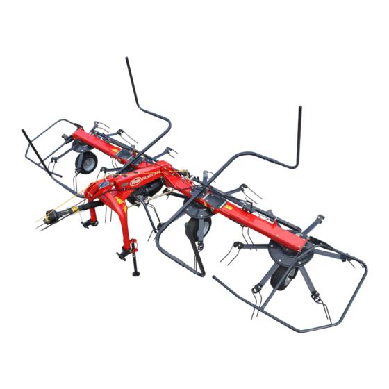
Getting to know the machine Designation of components Deflector bar Foldable hydraulic Deflector bar cylinder Outer device Centre device Tine Parking Running wheel stand axle 3 point trestle Tine supports rotor, Running wheel... -
Page 25: Technical Specifications
Getting to know the machine Technical specifications Dimensions Work position W (m) Transport position T (m) VF6590 VF6597 VF6590 VF6597 L = length 2.10 = length from the reflector 0.82 W = width 5.00 5.40 2.80 2.90 H = height 1.70 2.40 2.60... -
Page 26: Required Tractor Equipment
Getting to know the machine Weights Weights VF6590 VF6597 Total weight 492 kg 520 kg Permitted supported load 60 kg 51 kg Required tractor equipment Output / connections Minimum output of the tractor 32 kW Voltage supply for lighting 12 V, 7-pin plug socket ISO 1724 equipment 1 x single-acting control device Hydraulic connections... - Page 27 Getting to know the machine Airborne sound The airborne sound emissions from the machine are below the levels stipulated by machinery directive 2006/42/EC. emissions measurement • A-weighted sound level in the workplace: < 70 dB(A) • Currently C-weighted sound level: <...
-
Page 28: Delivery And Assembly
Delivery and assembly Checking the Delivery is in the fully assembled state Delivery and assembly Using the checklist, check the loose parts on delivery. If any parts of scope of delivery the machine have not been fitted or are missing, please contact your dealer. -
Page 29: Adapting The Pto Shaft
Delivery and assembly Adapting the The length of the PTO shaft was selected at the factory to suit almost all types of tractor. Only in exceptional cases is a correction of the PTO PTO shaft shaft length required on individual tractors. Check the length of the PTO shaft on each tractor prior to first use. -
Page 30: Shortening The Pto Shaft
Delivery and assembly Shortening the PTO shaft Pull the PTO shaft apart and connect one half to the tractor PTO shaft drive and one to the machine and secure them. Place the two shaft halves next to each other and: •... -
Page 31: Coupling The Machine
Coupling the machine Safety Coupling the machine Observe the safety information Observe the safety information. Disregard for safety information can lead to serious or fatal injury. See chapter »Safety instruc- tions«, page 7. Increased risk of injury When the machine is being coupled to the tractor, there is an increased risk of injury. - Page 32 Coupling the machine Tractors with quick- Follow the instructions for the quick-release coupling release couplings Follow the instructions below for tractors with quick-release couplings. If this requirement is ignored, the consequence may be damage to the machine and even life-threatening injuries. Slide guided cone balls suitable for the tractor onto the lower link Lower link Catch...
-
Page 33: Inserting The Parking Stand
Coupling the machine Coupling the top link When coupling the top link, ensure that the hitch pin is correctly fitted (see adjacent illustration). Hitch without Please note the following. Otherwise, the machine may be contact roller damaged: • With optional contact roller: Insert the hitch pin for the top link in the elongated hole and Hitch with secure using a safety splint. -
Page 34: Coupling The Pto Shaft
Coupling the machine Coupling the PTO shaft When coupling the PTO shaft, make sure it is in the correct position. Tractor Check whether the PTO shaft must be shortened before coupling. Shorten the PTO shaft if necessary. → »Adapting the PTO shaft«, page 29 Check that the tractor's PTO stub shaft is clean and lubricated. -
Page 35: Connections
Coupling the machine Connections Electrical Checking the electrical cables connections Check the electrical cables. The electrical cables must not chafe or hang loose. Electrical cables that have been torn away or worn through must be replaced. Damage to the machine may be caused as a result. -
Page 36: Hydraulic Connections
Coupling the machine Hydraulic Check hoses and couplings connections Check all hydraulic hoses for damage before connecting them. Check all hydraulic couplings for firm seating after connecting them. Defective hydraulic hoses and poorly fitting hydraulic connections can trigger unpredictable movements of the machine, causing severe damage to the machine as well as personal injury. - Page 37 Coupling the machine Connecting hydraulic Make sure the connection is correct couplings Ensure that the hydraulic system is connected correctly. Otherwise, damage to the machine and personal injury may be caused as a result. The tractor's single-acting hydraulic control device provides the means by which the rotors are raised and lowered.
-
Page 38: Preparing For Operation
Preparing for operation Safety Preparing for operation Observe the safety information Observe the safety information. Disregard for safety information can lead to serious or fatal injury. See chapter »Safety instruc- tions«, page 7. Secure the machine Secure the machine against accidental starting and rolling away. Use wheel chocks. -
Page 39: Moving The Machine To Its Work Position
Preparing for operation Moving the Observe the contour of the terrain machine to its Move the machine onto a flat surface or uphill before changing from the transport to the work position. Avoid inclines on which the work position combination (tractor and machine) could slip or overturn. The side device can swivel out uncontrollably. - Page 40 Preparing for operation Adjusting the rotor pitch Secure the machine +3° Secure the machine against inadvertent starting and rolling. The machine must be standing on firm and level ground and, if -3° necessary, be supported during the work. Unsecured or unsupported machines can cause accidents.
- Page 41 Preparing for operation Adjusting the tine support The ejection angle of the spring tines is adjusted by means of taper washers. This function enables consistent, uniform and optimum work Centre device results. The smaller the angle, the steeper and stronger the tine position.
-
Page 42: Road Transport
Road transport Safety Before transporting the machine on public roads, please read the Road transport following safety information. Compliance is mandatory and will help you to avoid accidents. Observe the safety information Observe the safety information. Disregard for safety information can lead to serious or fatal injury. - Page 43 Road transport Observe the contour of the terrain Move the machine onto ground that is as flat as possible before changing from the work position to the transport position. Avoid inclines on which the combination (tractor and machine) could slip or overturn.
-
Page 44: Prior To Road Transport
Road transport Prior to road When driving on public roads, the machine must be in the transport position. transport Clean machine before travelling on the road Before travelling on the road, remove all coarse dirt, crop residues and clods of earth from the machine and clean it. Crops or dirt that drop onto the road can cause slippery road conditions. - Page 45 Road transport Folding the machine Make sure the machine is standing level into the transport Before changing from the transport to the work position (and vice position versa), make sure the machine is standing level. The machine could tip over, particularly on hillside locations. Otherwise, damage to the machine and serious or fatal injury may be caused as a result.
-
Page 46: Road Transport
Road transport Road transport Follow the instructions below for road transport. This could cause traffic accidents and accidents with fatal consequences. Before pulling away, check the immediate vicinity. Always make sure that you have a clear field of vision and, in particular, look out for children within the operating area of the machine. -
Page 47: Preparations On The Field
Preparations on the field Safety Preparations on the field Observe the safety information Observe the safety information. Disregard for safety information can lead to serious or fatal injury. See chapter »Safety instruc- tions«, page 7. Switch off the tractor and secure it Before you dismount: Switch off the tractor. -
Page 48: Moving The Machine To Its Work Position
Preparations on the field Moving the Observe the contour of the terrain machine to its Move the machine onto a flat surface or uphill before changing from the transport to the work position. Avoid inclines on which the work position combination (tractor and machine) could slip or overturn. -
Page 49: Operation
Operation Safety Operation Observe the safety information Observe the safety information. Disregard for safety information can lead to serious or fatal injury. See chapter »Safety instruc- tions«, page 7. No riding on the machine Persons or objects must never be transported on the machine. Carrying passengers on the machine is life-threatening and prohibited. -
Page 50: Crop Processing
Operation Crop processing The following methods of crop processing are possible with the rotary tedder: • Tedding. • Turning. • Night swath laying (with swathing gear [+]). • Swath laying • Night swath turning (with swathing gear [+]). Tedding Turning Night swath laying When tedding, the freshly cut crop Turning ensures uniform drying of... -
Page 51: Use Of The Implement
Operation Use of the No persons in the working area implement Ensure that no persons are present in the slewing and working area of the machine. Persons could be caught by the machine within this area. This could result in fatal injury. Requirements Before starting work, check the following: Rotor pitch correctly adjusted? - Page 52 Operation Working speed Prevent crossing swathes As a general measure, prevent the crossing of mowing swathes. The crop is distributed unevenly and the machine is subjected to abrupt stresses. Damage to the machine may be caused as a result. Allow ample space when driving around obstacles Obstacles must be circumnavigated in good time and at a distance.
- Page 53 Operation Border tedding system The machine can be mechanically tilted to the left or to the right with the border tedding system. During border tedding, the machine will tail after at an angle, thus preventing the crop from being distributed beyond the field edge.
- Page 54 Operation Hydraulic border tedding When using the optionally available hydraulic border tedding system, system [+] proceed as follows: Adjusting border tedding: Slowly drive the tractor forwards. Use the tractor's double-acting hydraulic control device to move the machine to the desired border tedding position. Ending border tedding: Slowly drive the tractor forwards.
-
Page 55: Cleaning And Care
Cleaning and care Safety The following applies to all cleaning and care work: Cleaning and care Observe the safety information Observe the safety information. Disregard for safety information can lead to serious or fatal injury. See chapter »Safety instruc- tions«, page 7. Secure the machine •... -
Page 56: Cleaning
Cleaning and care Cleaning Switch off the tractor PTO shaft drive. Use the tractor's hydraulic control device to move the machine into its work position. Leave the machine coupled to the tractor's three-point lifting pickup. Lock the tractor's hydraulic control device. Switch off the tractor and secure it. -
Page 57: Parking And Storage
Parking and storage Setting down the When setting down, storing and parking the implement special safety Parking and storage precautions have to be observed: machine in a secure position Observe the safety information Observe the safety information. Disregard for safety information can lead to serious or fatal injury. -
Page 58: After The End Of The Season
Parking and storage Uncouple and secure To uncouple the implement from the tractor proceed as follows: the machine Stop the machine in the work position on firm, secure, level ground. Close the ball valve and release the hydraulic couplings. Insert hydraulic couplings into the storage pockets on the machine. Disconnect the lighting equipment plug [+] and place it into the storage pockets on the machine. -
Page 59: Maintenance
Maintenance Safety The following applies to all servicing work: Maintenance Observe the safety information Observe the safety information. Disregard for safety information can lead to serious or fatal injury. See chapter »Safety instruc- tions«, page 7. Requirements for maintenance work Only perform the maintenance operations if you have the required expert knowledge and suitable tools. - Page 60 Maintenance Never manoeuvre or position in the transport position Never manoeuvre implements with three-point pickup in transport position if the machine is not properly connected to the tractor's three-point lifting pick up. When manoeuvring, also make sure that all parking stands are retracted and secured. Otherwise, damage to the machine or life-threatening injuries may caused as a result.
- Page 61 Maintenance Protective measures Additives in oils and lubricants may have adverse effects on health. As marking in accordance with the hazardous goods regulation is not when handling oils or necessary, please always ensure the following: lubricants Avoid skin contact Avoid skin contact with these materials. Protect your skin by means of protective skin cream or oil-resistant gloves.
-
Page 62: General
Maintenance General This information relates to general servicing work. For any maintenance work, the machine must be in the work position and be secured in place. If the transport position is required, find the relevant instructions. Lower the machine to the work position. Secure the machine against rolling away by using chocks. - Page 63 Maintenance Maintenance terms Listed in this table are short explanations of the most important maintenance terms. Task Explanation Greasing Apply grease to the slide surfaces using a brush. Lubrication One or two presses of the grease gun, unless specified otherwise. Unless specified otherwise, use only plant-based oils, such as rapeseed oils.
-
Page 64: Screwed Connections
Maintenance Screwed connections Tightening bolts All bolts must be retightened: • After the first 5 hours of operation and • According to the frequency of use, • But at least once a season. Tightening torques All screwed connections must be tightened in accordance with the table below, if no other torques are specified. - Page 65 Maintenance Special Observe the special tightening torques for the following screwed connections: tightening torques • 90 Nm spring tines and tine supports, outer. 90 Nm • 120 Nm tine supports, inner. 120 Nm • 20 Nm running wheel nut. 20 Nm wheel nut...
-
Page 66: Lubrication Points For Oil Lubrication
Maintenance Lubrication points The machine has one main gear box and four rotor gears. for oil lubrication The main gear box is lubricated with oil and requires almost no maintenance. However, the oil level must be checked if there is a visible loss of oil. - Page 67 Maintenance Checking the The maintenance-free main gear box is filled ex works with sufficient oil. main gear box Checking the oil level: Ensure the machine is level. Undo the check screw completely. Check the oil level. • Correct oil level: bottom edge of check screw hole. Check the main gear box if there is visible loss of lubricant when the machine is in a horizontal position –...
-
Page 68: Lubrication Points For Grease Lubrication
Maintenance Lubrication points Lubricate all of the areas marked in the illustration as follows: for grease • after 30 hours of operation. lubrication • before and after the season. • each time after cleaning with a high-pressure cleaner. Working with a Before applying the grease gun grease gun clean lubricating nipples and... -
Page 69: Lubricating The Pto Shafts
Maintenance Lubricating the The manufacturer's own operating manual is attached to each PTO shaft. This includes detailed information on the relevant version of the PTO shafts PTO shaft. Check the guard components Check all guard components of the PTO shafts for wear or damage (visual inspection). -
Page 70: Tyres
Maintenance Tyres Do not drive with worn or damaged tyres Replace worn or damaged tyres immediately. There is a high risk of accident when driving on the road with such tyres. Tyre pressure Check the tyre pressures on a regular basis: •... -
Page 71: Hydraulics
Maintenance Hydraulics Hydraulic system at zero pressure Work must only be performed on the hydraulic system if the tractor and machine hydraulic system is at zero pressure. A pressurised hydraulic system can trigger unpredictable movements of the machine and can cause serious machine damage and personal injury. -
Page 72: Accessory Equipment
Accessory equipment Available options Optional additional equipment does not form part of the standard Accessory equipment scope of delivery, and is indicated by a plus symbol [+]. Additional equipment is available to order from your dealer. Tine saver If the tines are broken, the tine savers prevent the loose, broken part from being lost. -
Page 73: Spare Wheel
Accessory equipment Contact roller To prevent damage to the stubble on particularly uneven terrain, as well as to avoid leaving any crop behind, a contact roller can be fitted to the 3 point trestle as additional equipment. The assembly instructions for your machine describe how to fit the additional equipment. - Page 74 Accessory equipment Slope locking mechanism The slope locking mechanism improves ground contact when travelling on hills and ensures that the rotors gather the crop reliably, even on hillside locations. The slope locking mechanism is fitted between the 3 point trestle and the machine frame.
-
Page 75: Fault Elimination
Fault elimination Fault Faults can often be eliminated quickly and easily. Before contacting Fault elimination Customer Service, refer to the table to check whether you can remedy the fault yourself. What to do in the event of a fault In case of a fault, proceed as follows: Immediately stop operation. -
Page 76: Circuit Diagrams
Circuit diagrams Hydraulic diagram Circuit diagrams Left Right hydraulic cylinder hydraulic cylinder for folding for folding Hydraulic coupling Border tedding system [+] stop valve Tractor... -
Page 77: Lighting Circuit Diagram [+]
Circuit diagrams Lighting circuit diagram [+] 2/54g 3/31 5/58R 6/54 7/58L Connector 7-pin in accordance with ISO 1724 Yellow Green White Brown Black Connector and socket 7-pin in accordance with ISO 1724 Yellow Black Right blinker Right brake light Earth Brown Left blinker Right rear light... -
Page 78: Decommissioning
Decommissioning Environment During decommissioning, the individual parts must be disposed of Decommissioning properly and in an environmentally friendly manner. Please observe the waste disposal guidelines that are currently in force. Plastic parts Plastic parts can be disposed of in normal household waste (residual waste), depending on the laws specific to your country. -
Page 79: Ec Conformity Declaration
2006/42/EC Taarupstrandvej 25 DK-5300 Kerteminde Denmark declare with sole responsibility that the product CondiMaster 4622 / CondiMaster 5222 Fanex 464 / Fanex 524 8446 / 8452 and its accessories Model: 6590 / 6597 Valid from machine number: VF65902110 / VF65974001... - Page 80 EC Conformity Declaration...
-
Page 81: Index
Index Index shutdown after the season uncoupling Accessory equipment Maintenance Lubrication points Maintenance intervals Border tedding Border tedding system Adjusting Manual disposal of Protective measures Care Check list Preparation Work position Work position Circuit diagrams Preparations on the field Hydraulic diagram Preparing for operation Lighting Proper use...
Need help?
Do you have a question about the Fanex 464 and is the answer not in the manual?
Questions and answers