
Related Manuals for Vicon Fanex 524 T


Summary of Contents for Vicon Fanex 524 T
- Page 1 Fanex 524 T Assembly instructions Original assembly instructions Edition 04.2013 Date of print 12.2013 Language Machine number VF69152000 – Model VF6915 Document number VF16660677.EN...
- Page 2 Kverneland Group Kerteminde AS Taarupstrandvej 25 DK-5300 Kerteminde Denmark Tel: +45 65 19 19 00 Copyright by Kverneland Group Gottmadingen N. V., Germany. Reproduction, transfer to other media, translation or the use of extracts or parts of this manual without the explicit permission of Kverneland, is not permitted. All rights reserved. The contents of this operating manual are subject to change without notice.
-
Page 3: Table Of Contents
Table of contents Table of contents Preliminary information ......Target group for these assembly instructions Meaning of the symbols Safety ............For your safety Screw and bolt tightening torques Direction and rotary direction Overview ............ Designation of components Crate packaging ........Assembly groups in crate packaging Basic machine Fitting the wheels... -
Page 4: Preliminary Information
Preliminary information Target group for These instructions are intended for authorised dealers, workshops Preliminary information and agents qualified in the field of agricultural mechanical engi- these assembly neering. instructions For your safety You must familiarise yourself with the contents of these assembly instructions before assembly or operating the machine. -
Page 5: For Your Safety
Safety For your safety Please carefully read and observe the safety information in this Safety chapter prior to assembly. All persons involved in assembling or setting up this machine must read and pay close attention to the assembly instructions that follow. Danger indicators signify the risk of serious injury or death. - Page 6 Safety General safety and • Responsibilities for the various activities on the machine must be clearly defined and maintained. There must not be any confusion accident prevention regarding responsibilities, otherwise the safety of the assembly regulations personnel is put at risk. •...
-
Page 7: Screw And Bolt Tightening Torques
Safety Screw and bolt Note the tightening torques that are shown in the table or specified in the text. The torque specifications refer to a dry coefficient of friction tightening torques (0.12). 10.9 12.9 9.9 Nm (7.3 ft.lbs) 14 Nm (10.3 ft.lbs) 17 Nm (12.5 ft.lbs) 24 Nm (17.7 ft.lbs) 34 Nm (25 ft.lbs) -
Page 8: Overview
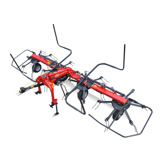
Overview Designation of Overview components Central trans- Foldable hydraulic Centre device Rear parking Guard bar Guard bar mission cylinder stand Outer device Front parking Rotor Running wheel Tine support stand axle Drawbar Tines Rotor gear Running wheel... -
Page 9: Assembly Groups In Crate Packaging
Crate packaging Assembly groups Crate packaging in crate packaging Tine support Centre device Outer device Guard bar for the outer device Guard bar for the centre device PTO shaft Document box Rear parking stand Rotor disc Drawbar Wheels with wheel axles... - Page 10 Crate packaging Wheels and wheel axles Wheels Wheel axles Wheels Guard bars and tine supports Rotor Tines Tine support Guard bar for right-hand Guard bar for the left- Guard bar for the centre side device hand side device device...
- Page 11 Crate packaging Requirements • Suitable flat surface approx. 10 x 10 m as assembly space. • Lifting gear with lifting accessories for at least 900 kg. • Floor conveyor (pallet truck or fork lift) with a fork length of at least 1,800 mm.
-
Page 12: Basic Machine
Crate packaging Basic machine The basic machine consists of the preassembled centre and side device combination. Use suitable lifting accessories to remove the machine elements from the crate. Loosen all fastenings (wires, lashing straps). Use a crane to place the basic machine on stands and secure in place. -
Page 13: Fitting The Wheels
Crate packaging Fitting the wheels Secure the folded-out basic machine using suitable lifting accessories. Fit the rotor discs and the wheel axles with wheels. Pay attention to Rotor disc the position of the wheel axles. Serrated flange bolt Slightly fasten the rotor discs in place using two serrated flange bolts. -
Page 14: Fitting The Drawbar
Crate packaging Fitting the drawbar When fitting the drawbar, the guard bars for the centre device are fitted in order for the drawbar to be connected to the basic machine. Guard bar for the centre device The drawbar is fitted in several steps: »Fitting the guard bar«, page 15 »Connecting the drawbar to the centre device«, page 16 M10 x 30... - Page 15 Crate packaging Fitting the guard bar Remove the two M16 x 200 bolts from the centre device/gear box M16 x 200 (top). Remove the four pre-fitted M12 x 130 bolts from the fastening positions on the guard bar. Loosely pre-fit the M10 x 30 bolts on the guard bar. Thread the M10 x 30 bolts into the elongated holes on the centre device and align the guard bar.
- Page 16 Crate packaging Connecting the drawbar to the centre device Connect the drawbar to the basic machine: Bring the drawbar to the centre device. Bearing shaft First, insert the drawbar's bearing shaft into the bearing shaft holder holder on the guard bar (A). Push the guard bar (C) onto the drawbar.
- Page 17 Crate packaging Align the drawbar centrally. Dowel pin Secure the drawbar's bearing shaft with an 8 x 36 dowel pin. Using an M10 nut and two M12 x 130 bolts with M12 washers, fit the M12 x 130 left-hand guard bar (C) tightly to the centre device. Washer Quantity Part...
-
Page 18: Fitting Attachment Parts For The Drawbar
Crate packaging Fitting attachment Fit the drawbar cylinder and the necessary attachment parts as follows: parts for the drawbar »Fitting the drawbar cylinder«, page 19 »Fitting the crank«, page 19 »Fitting the hexagonal profile«, page 19 »Fitting the drawbar spring«, page 20 Overview End cap Drawbar spring... - Page 19 Crate packaging Fitting the drawbar cylinder Using suitable lifting accessories, raise the drawbar until the Split pin attachment point is approx. 400 mm above the ground. Screw the drawbar cylinder into the spindle nut from below. Distance from the upper edge of the spindle nut to the hole for the dowel pin: 53 mm.
-
Page 20: Fitting The Protective Pot
Crate packaging Fitting the drawbar spring Hook the drawbar spring into the upper plate. Drawbar spring Hook the eye bolt into the spring. Turn the upper nut on the eye bolt and, with the washer, guide it through the hexagonal profile. Secure the eye bolt using a washer and the lower nut. -
Page 21: Laying The Control Cables
Crate packaging Laying the control The control cables for the transport lock (black control cables) are knotted to the corresponding levers and guided forwards through the cables guide eyes as illustrated below. Secure the black control cable to the lever for the left-hand transport lock. -
Page 22: Routing The Hydraulic Lines
Crate packaging Routing the hydraulic lines The hydraulic lines are preassembled. Route the preassembled hydraulic lines through the left-hand arm of the drawbar as illustrated. Fasten the hydraulic lines to the cylinders using cable ties. Fasten the hydraulic line to the drawbar using cable ties. Quantity Part Hydraulic line... -
Page 23: Fitting The Tine Supports
Crate packaging Fitting the tine When fitting the tine support, pay attention to the rotational direction of the rotor and the tine position. The tine support must be fitted to either supports the left or right-hand side of the rotor, depending on the rotational direction. - Page 24 Crate packaging Taper washers The ejection angle of the spring tines can be adjusted as required using the taper washers. The taper washers are part of the scope of delivery and are delivered to the customer in a separate bag. The assembly instructions for the taper washers can be found in the operating manual.
-
Page 25: Assembling The Protective Equipment
Crate packaging Assembling the Guard bar for the centre device: protective Place the angle brackets onto the guard bar adapters. Securely fasten the angle brackets to the adapters. equipment • Ensure that the Allen bolts are in the correct position. They are recessed in the guard bar and tightened. - Page 26 Crate packaging Fitting the guard bar Guard bar for the outer device: Securely fasten the guard bars on both of the outer devices. Outer device Guard bar for the outer device Quantity Part Guard bar for the outer device M10 x 30 bolts M10 washers M10 nuts...
-
Page 27: Safety Chain For Usa And Canada
Crate packaging Safety chain for USA and Canada There is an attachment for a safety chain on the front left-hand side of the drawbar. Fit the safety chain as illustrated. Quantity Part Safety chain M16 x 60 bolt 17 x 58 x 8 washer 17 x 58 x 8 washer Sleeve M16 washers... -
Page 28: Final Assembly With Crate Packaging
Crate packaging Final assembly The basic machine and drawbar are correctly connected. The wheels are fitted. The machine is in the work position. with crate packaging Now proceed as follows: »Final tasks«, page 30... -
Page 29: Circuit Diagrams
Circuit diagrams Hydraulic diagram Circuit diagrams Left Right hydraulic cylinder hydraulic cylinder for folding for folding Drawbar cylinder Hydraulic coupling stop valve Tractor... -
Page 30: Final Tasks
Final tasks Trial run Final tasks No persons within the slewing range There is an extreme risk of injury within the slewing range from slewing or folding machine parts. With the aid of the operating manual, check the following after assembly is complete.
Need help?
Do you have a question about the Fanex 524 T and is the answer not in the manual?
Questions and answers