
Related Manuals for Vicon Fanex 834 T


Summary of Contents for Vicon Fanex 834 T
- Page 1 Fanex 834 T Assembly instructions Original assembly instructions Edition 04.2012 Date of print 07.2012 Language Machine number VF69181501 – Model VF6918 Document number VF16648880.EN...
- Page 2 Kverneland Group Kerteminde AS Taarupstrandvej 25 DK-5300 Kerteminde Denmark Tel: +45 65 19 19 00 Copyright by Kverneland Group Gottmadingen N. V., Germany. Reproduction, transfer to other media, translation or the use of extracts or parts of this manual without the explicit permission of Kverneland, is not permitted. All rights reserved. The contents of this operating manual are subject to change without notice.
-
Page 3: Table Of Contents
Table of contents Table of contents Preliminary information ......Target group for these assembly instructions Meaning of the symbols Safety ............For your safety Screw and bolt tightening torques Direction information Overview ............ Designation of components Assembly groups in crate packaging Assembly group for pallet packaging Small parts Set of lights... -
Page 4: Preliminary Information
Preliminary information Target group for These instructions are intended for authorised dealers, workshops Preliminary information and agents qualified in the field of agricultural mechanical engi- these assembly neering. instructions For your safety You must familiarise yourself with the contents of these assembly instructions before assembly or operating the machine. -
Page 5: For Your Safety
Safety For your safety Please carefully read and observe the safety information in this Safety chapter prior to assembly. All persons involved in assembling or setting up this machine must read and pay close attention to the assembly instructions that follow. Danger indicators signify the risk of serious injury or death. - Page 6 Safety General safety and Observe the following rules and regulations: accident prevention • Responsibilities for the various activities on the machine must be regulations clearly defined and maintained. There must not be any confusion regarding responsibilities, otherwise the safety of the assembly personnel is put at risk.
-
Page 7: Screw And Bolt Tightening Torques
Safety Screw and bolt Note the tightening torques that are shown in the table or specified in the text. The torque specifications refer to a dry coefficient of friction tightening torques (0.12). 10.9 12.9 9.9 Nm (7.3 ft.lbs) 14 Nm (10.3 ft.lbs) 17 Nm (12.5 ft.lbs) 24 Nm (17.7 ft.lbs) 34 Nm (25 ft.lbs) -
Page 8: Overview
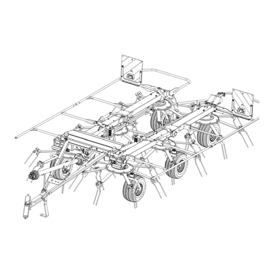
Overview Designation of Overview components Adjusting lever for the Hydraulic cylinder Deflector frame Outer device Transport locking for swivelling border tedding position Side device Central transmission Rotor gear Wheel Running wheel axle Sustainer Drawbar Tine arm Rotor Tines... -
Page 9: Assembly Groups In Crate Packaging
Overview Assembly groups in crate packaging Flow divider Centre device Deflector frame Left side device Wheel Right-hand outer device Left-hand Right-hand outer device side device Steering linkage PTO shaft with 2 x single Tine support joints Deflector frame with transport locking bar Assembly group Page... -
Page 10: Assembly Group For Pallet Packaging
Overview Assembly group for pallet packaging Left-hand Right-hand outer device outer device Deflector frame Right-hand Left side device side device Tine support PTO shaft with 1 x wide- Centre device angle joint Wheel Assembly group Page »Basic machine« »Fitting the outer device« »Fitting the upper hitch drawbar«... -
Page 11: Small Parts
Overview Small parts Scouring protection Tine gauge coil Bolts and serrated flange bolts for the tine supports Wheel chock with support and holder Assembly parts for deflector frame Assembly parts for warning signs Assembly parts for drawbar Pins for border tedding system Assembly Bearing plate for the drawbar,... -
Page 12: Crate Packaging
Crate packaging Requirements • Suitable flat surface approx. 10 x 10 m as assembly space. Crate packaging • Lifting gear with lifting accessories for at least 1,500 kg. • Floor conveyor (pallet truck or fork lift) with a fork length of at least 1,800 mm. -
Page 13: Fitting The Centre And Side Devices
Crate packaging Fitting the centre Use suitable lifting accessories to remove the machine elements from the crate. and side devices The side devices are fitted to the centre device ex works. Side device Loosen all fastenings (wires, lashing straps). ... -
Page 14: Running Wheel Axles
Crate packaging Running wheel Pay attention to the position of the running wheel axles axles When fitting the running wheel axles, make sure that they are correctly positioned. If fitted incorrectly, running wheel axles may cause damage to the machine. Overview of the running wheel axles Running wheel axle... - Page 15 Crate packaging Fitting running wheel During assembly, ensure that the running wheel axles are fitted and screwed in the correct position on the centre and side device. axles with wheel swing brakes Front running wheel axle Rear running wheel axle Quantity Part Running wheel axle with ...
- Page 16 Crate packaging Fitting the running wheel The running wheel locking mechanism allows even working on slopes. locking mechanism Place the running wheel locking mechanism onto the carrier. Insert the pin into the outer hole and secure with a safety splint. Carrier ...
-
Page 17: Fitting The Drawbar For The Lower Hitch
Crate packaging Fitting the Fit the drawbar to the centre device. Secure the centre device and drawbar with suitable lifting gear. drawbar for the lower hitch Lift the preassembled drawbar and move into the correct position to the centre device (9). ... - Page 18 Crate packaging Fitting the drawbar The spindle is prefitted to the drawbar ex works. The drawbar cylinder is already connected to the machine hydraulics ex works. hydraulics for the lower hitch Proceed as follows: Turn the spindle out of the spindle nut. ...
- Page 19 Crate packaging Fitting the crank Fit the crank onto the spindle and secure with a dowel pin. Lubricate the spindle with a brush. Quantity Part Crank 8 x 50 dowel pin Drawbar...
-
Page 20: Fitting The Outer Devices
Crate packaging Fitting the outer Fit the two outer devices to the side devices. Note the position of the rotor discs. Incorrect positioning of rotor discs will cause damage to devices the machine. Position of the rotor The tine arm fastening holes act as reference points for adjustment. discs Checking the correct position... - Page 21 Crate packaging Correcting the position If the rotor discs are not aligned correctly on the machine after of the rotor discs assembly, the machine must be moved into the work position for alignment. Proceed as follows: Connect hydraulic system. ...
- Page 22 Crate packaging Connecting the outer The rotor discs of the side and outer devices are aligned correctly. device to the side device Connect the drive shaft of the side device with the single joint of outer device (1) in the correct position. ...
- Page 23 Crate packaging Fitting the rear Fit the running wheel and the adjusting lever to the appropriate outer device. running wheel and adjusting lever The axles of the rear running wheels on the outer device point inwards. Place the washer (2) onto the running wheel axle. ...
- Page 24 Crate packaging Fitting the On both sides, fit the control rod to the adjusting lever of the rear outer devices. control rod Insert the control rod into the steering rod. Ensure that one bore and the dowel pin are visible on both control rods.
-
Page 25: Hydraulics For The Lower Hitch
Crate packaging Hydraulics for the For information on the hydraulic connection of machines with an upper hitch, see chapter Pallet packaging. lower hitch See »Upper hitch hydraulics«, page 36. Connecting the hydraulics Observe the safety information in the assembly and operating manuals. -
Page 26: Final Assembly For Crate Packaging
Crate packaging Final assembly for The side devices with the preassembled outer devices are connected to the centre device. The rotor discs and the universal joints are in the crate packaging correct position. Now proceed as follows: Follow the instructions in the chapter »Final assembly« from page... -
Page 27: Pallet Packaging
Pallet packaging Requirements • Suitable flat surface approx. 10 x 10 m as assembly space. Pallet packaging • Lifting gear with lifting accessories for at least 1,500 kg. • Floor conveyor (pallet truck or fork lift) with a fork length of at least 1,800 mm. -
Page 28: Basic Machine
Pallet packaging Basic machine The basic machine consists of centre, side and outer devices and is preassembled ex works. Preparing the basic machine Loosen all fastenings (wires, lashing straps). Secure the basic machine with lifting gear. Lift the basic machine and remove the pallet. Aligning the running wheels ... - Page 29 Pallet packaging Fitting the guard cone Fit the guard cone to the central transmission. Secure the guard cone with a jubilee clip. Jubilee clip Guard cone...
-
Page 30: Fitting The Outer Device
Pallet packaging Fitting the outer To carry out further assembly steps, the outer device is secured and lowered using suitable lifting gear. To do this, proceed as follows: device Remove both transport locking devices. The transport locking devices are no longer needed. Transport locking device ... - Page 31 Pallet packaging Fitting the rear Fit the running wheel and the adjusting lever to the appropriate outer device. running wheel and adjusting lever The axles of the rear running wheels on the outer device point inwards. Place the washer (2) onto the running wheel axle. ...
- Page 32 Pallet packaging Fitting the On both sides, fit the control rod to the adjusting lever of the rear outer devices. control rod Insert the control rod into the steering rod. Ensure that one bore and the dowel pin are visible on both control rods.
-
Page 33: Fitting The Upper Hitch Drawbar
Pallet packaging Fitting the upper The upper hitch drawbar is already preassembled ex works. When carrying out assembly work on the centre device, proceed as follows. hitch drawbar Secure the drawbar with suitable lifting gear. Drawbar Prepare an assembly stand. ... -
Page 34: Upper Hitch
Pallet packaging Fitting the drawbar The spindle is already prefitted to the drawbar ex works. The drawbar cylinder is already connected to the machine hydraulics ex works. hydraulics for the upper hitch Proceed as follows: Turn the spindle out of the spindle nut. ... - Page 35 Pallet packaging Quantity Part 20 x 72 pin 5 x 32 split pins Drawbar cylinder M12 x 150 eye bolt 235 x 61 spring M12 nuts M12 washer Hook the spring into the support on the drawbar. Guide the eye bolt of the spring through the hole in the centre device, screw tight and secure with a locknut.
-
Page 36: Hydraulics
Pallet packaging Upper hitch Observe the safety information in the assembly and operating hydraulics manuals. Connecting the The hydraulic hoses on the upper hitch are already connected to the hydraulic cylinders ex works. Route the hoses underneath the right- hydraulics hand drawbar profile. -
Page 37: Coupling The Machine
Pallet packaging Coupling the The upper hitch of the machine is equipped for coupling to the drawbar eye. To couple the implement, proceed as follows. machine Upper hitch Lower tractor's lower links if using the upper hitch Lower the lower links on the tractor. The lower links can come into contact with the drawbar or the PTO shaft when cornering and otherwise, damage to the machine may be caused as a result. -
Page 38: Final Assembly For Pallet Packaging
Pallet packaging Final assembly for The side devices with the preassembled outer devices are connected to the centre device. The rotor discs and the universal joints are in the pallet packaging correct position. Now proceed as follows: Connect the »Upper hitch hydraulics«, page 36 ... -
Page 39: Final Assembly
Final assembly Folding the Final assembly Observe the contour of the terrain machine into the Move the machine onto a flat surface or uphill before changing from transport to work position. Avoid inclines on which the work position combination (tractor and machine) could slip or overturn. The side device can swivel out uncontrollably. -
Page 40: Setting Straight-Ahead Travel
Final assembly Setting straight- The machine is partially preset. Observe the prescribed sequence when setting the machine. The border tedding system must not be ahead travel set. Proceed as follows: • »1. Aligning the outer running wheels« • »2. Aligning the side device« •... - Page 41 Final assembly 2. Aligning the side device Ensure that border tedding position is not set. Use the tractor's hydraulic control unit to fold the machine into its work position. Check if all frame parts are in a straight line. Line If the frame parts do not form a straight line when in the work position, proceed as follows:...
- Page 42 Final assembly 3. Align the outer running wheels for transportation Release both eccentrics (E) on the outer devices. Use the tractor's hydraulic control unit to fold the machine into the transport position. Check if the hydraulic cylinders are fully retracted. ...
-
Page 43: Fitting The Tine Supports
Final assembly Fitting the tine When fitting the tine supports, pay attention to the direction of rotation of the rotor and the tine position. Depending on the direction of rotation supports of the rotors, tine supports are fitted on the left or right. Aligning the ... - Page 44 Final assembly Connecting the tine During fitting, pay attention to the rotor's direction of rotation. supports See “Aligning the tine supports” on page 43. to the rotor disc To connect the tine supports to the rotor disc, proceed as follows: ...
-
Page 45: Fitting The Deflector Frames
Final assembly Fitting the Fit the deflector frames to the two side devices, as shown in the illustration. deflector frames Note the correct position of the front deflector frames. Fit the wheel chock holder to the left-hand rear deflector frame. Wheel chock holder 550 mm 400 mm... - Page 46 Final assembly Attaching warning Attach the warning signs and lighting equipment to the two side devices, as shown in illustration. signs and lighting Fit the sticker holder on the left warning sign. equipment Fit the support for the wheel chocks (9) to the wheel chock holder (8).
-
Page 47: Routing Electrical Cables
Final assembly Routing electrical Ensure that there is sufficient free space when routing electric cables: cables • Between the rear and front deflector frames, and • when routing along on the centre device. The electric lines are connected to the lighting equipment ex works. Cable loop When switching from transport to work position, check whether the loops are protected against pulling and shearing. -
Page 48: Pto Shaft
Final assembly PTO shaft Check the length of the PTO shaft on each tractor prior to first use. The length of the PTO shaft was selected at the factory to suit almost all types of tractor. It is only necessary to correct the length of the PTO shaft in exceptional cases. - Page 49 Final assembly Shortening the PTO shaft Precisely determine the correct length of the shaft. Shorten the guard tube. Shorten the forming tubes for the drive. The length of the two cut-off ends must be the same. Deburr and clean the cut edges of the guard tubes and forming tubes to ensure that they are smooth and clean.
-
Page 50: Setting Up Work
Final assembly Setting up work Adjusting the working depth The clearance of the tines from the ground is adjusted in the work position via the crank. Use the tractor's hydraulic control unit to fold the machine into its Crank work position. - Page 51 Final assembly Setting the trailing If the running wheel locking mechanism is released, the wheel swings around the wheel axle. This swinging movement can be controlled by characteristic setting the wheel swing brake. To ensure smooth running of the wheels, all wheel swing brakes must be set to the same braking force before delivery of the machine.
- Page 52 Final assembly Measuring the braking The braking force of the wheel swing brakes is measured using a force using the spring spring balance. The wheels must not be in contact with the ground during measuring. balance Fold the machine into its transport position. ...
-
Page 53: Accessories
Accessories Accessories Optional additional equipment does not form part of the standard Accessories scope of delivery, and, in this manual, is indicated by a plus symbol [+]. Additional equipment is available to order from your dealer. Tine saver If the tines are broken, the tine savers prevent the loose, broken part from being lost. - Page 54 Accessories Swathing gear The swathing gear reduces the speed of the PTO shaft. The crop is not spread but deposited between two rotors as a swath. Remove the existing protective pot on the central transmission. Slide the swathing gear with the protective pot onto the central transmission shaft and secure it with a circlip.
-
Page 55: Hydraulic Border Tedding System
Hydraulic border tedding system The hydraulic border tedding system is not included in the standard Hydraulic border tedding system scope of delivery. Fitting can only be carried out when the machine is fully assembled. Fold the machine into its work position. ... -
Page 56: Final Operations
Final operations Trial run Final operations No persons within the slewing range There is an extreme risk of injury within the slewing range from slewing or folding machine parts. After fitting, check the following points: • Length of PTO shaft. See »PTO shaft«, page 48. •...
Need help?
Do you have a question about the Fanex 834 T and is the answer not in the manual?
Questions and answers