Table of Contents
Advertisement
Quick Links
OPERATOR'S MANUAL
INCLUDING: OPERATION, INSTALLATION & MAINTENANCE
It is the responsibility of the employer to place this information in the hands of the operator. Keep for future reference.
SERVICE KITS
637118-C for air section repair (see page 6).
637138-63 for fluid section repair (see page 4).
PUMP DATA
Models . . . . . . . . . . . . . . . . . . . 650719-C
Application . . . . . . . . . . . . . . Diesel Fuel, Kerosene, Aviation
Pump Type . . . . . . . . . . . . . . . U.L. Listed Metallic Air Operated
Material . . . . . . . . . . . . . . . . . . see Model Description Chart
Weight . . . . . . . . . . . . . . . . . . . . . . . . . . . . . . 58.44 lbs (26.5 kgs)
Maximum Air Inlet Pressure . . . . . . . . 50 psig (3.4 bar)
Maximum Outlet Pressure . . . . . . . . . . 50 psig (3.4 bar)
Maximum Flow Rate
(flooded inlet)
Displacement / Cycle @ 100 psig. . . . 0.64 gal. (2.42 lit.)
Maximum Particle Size . . . . . . . . . . . . . 1/4" dia. (6.4 mm)
Maximum Temperature Limits (diaphragm / ball / seal /
seat material)
Acetal . . . . . . . . . . . . . . . . . . . . -20° to 180° F (-29° to 82° C)
PVDF . . . . . . . . . . . . . . . . . . . . . 10° to 200° F (-12° to 93° C)
Viton® . . . . . . . . . . . . . . . . . . . . -40° to 350° F (-40° to 177° C)
Dimensional Data . . . . . . . . . . . . . . . . . . . see page 8
Noise Level @ 70 psig, 60 c.p.m. . . . . . . 77.7 db(A)
The pump sound pressure levels published here have been updated to
an Equivalent Continuous Sound Level (L
S1.13-1971, CAGI-PNEUROP S5.1 using four microphone locations.
INGERSOLL RAND COMPANY INC
209 NORTH MAIN STREET – BRYAN, OHIO 43506
(800) 495-0276
FAX (800) 892-6276
arozone.com
2" DIAPHRAGM PUMP
U.L. LISTED, 1:1 RATIO, METALLIC
READ THIS MANUAL CAREFULLY BEFORE INSTALLING,
OPERATING OR SERVICING THIS EQUIPMENT.
Fuel, Fuel Oil and Unleaded Fuel
Double Diaphragm for use with
Petroleum Product Dispensing
Systems
. . . 75 gpm (283.9 lpm)
) to meet the intent of ANSI
Aeq
© 2023
CCN 15201445
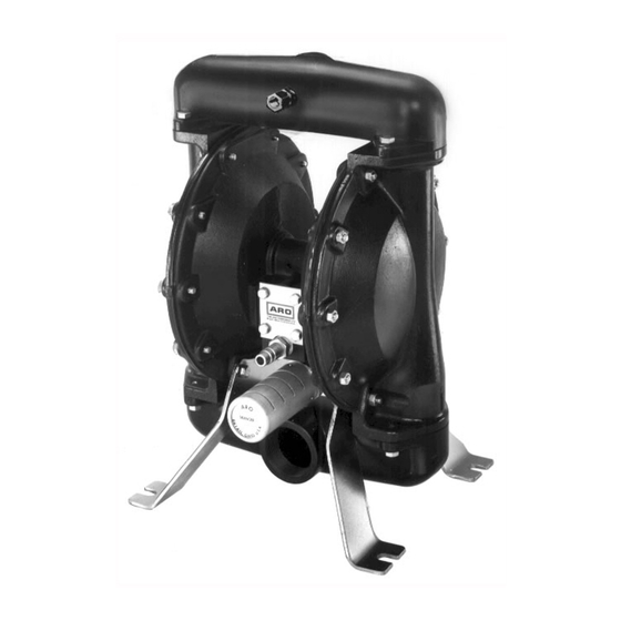
Figure 1
MODEL DESCRIPTION CHART
Diaphragm Material
9 - Viton
Center Body Material
Aluminum
Fluid Connection
2 - 11-1/2 N.P.T.F. - 1
Fluid Cap / Manifold Material, Hardware
Aluminum / Aluminum, Steel hardware
Seat Material
PVDF
Ball Material
Acetal
650719-C
RELEASED:
8-11-03
REVISED:
1-27-23
(REV. K)
65071 9 - C
Advertisement
Table of Contents

Related Manuals for Ingersoll-Rand ARO 650719-C


Summary of Contents for Ingersoll-Rand ARO 650719-C
- Page 1 OPERATOR’S MANUAL 650719-C INCLUDING: OPERATION, INSTALLATION & MAINTENANCE RELEASED: 8-11-03 REVISED: 1-27-23 (REV. K) 2" DIAPHRAGM PUMP U.L. LISTED, 1:1 RATIO, METALLIC READ THIS MANUAL CAREFULLY BEFORE INSTALLING, OPERATING OR SERVICING THIS EQUIPMENT. It is the responsibility of the employer to place this information in the hands of the operator. Keep for future reference. SERVICE KITS 637118-C for air section repair (see page 6).
-
Page 2: Operating And Safety Precautions
OPERATING AND SAFETY PRECAUTIONS READ, UNDERSTAND AND FOLLOW THIS INFORMATION TO AVOID INJURY AND PROPERTY DAMAGE. HAZARDOUS MATERIALS. Can cause serious WARNING EXCESSIVE AIR PRESSURE HAZARDOUS MATERIALS injury or property damage. Do not attempt to return STATIC SPARK HAZARDOUS PRESSURE a pump to the factory or service center that contains hazardous material. -
Page 3: General Description
Loctite® is a registered trademark of Henkel Corporation y ARO® is a registered trademark of Ingersoll-Rand Company y y262™, 271™ and 572™ are trademarks of Henkel Corporation y Viton® is a registered trademarks of the Chemours Company y... -
Page 4: Fluid Section Disassembly
PARTS LIST / 650719-C FLUID SECTION 637138-63 fluid section service kits include: Balls (item 22), diaphragms (item 7) plus items 2, 3, 19 and 94276 Lubriplate® FML-2 (page 6). PARTS LIST Item Description Qty Part No. [Mtl] Item Description Qty Part No. - Page 5 PARTS LIST / 650719-C FLUID SECTION FOR THE AIR MOTOR SECTION, SEE PAGES 6 & 7. Torque Sequence 26 ( 29 ( 14 ( 26 ( ) ASSEMBLY TORQUE REQUIREMENTS ( NOTE: DO NOT OVERTIGHTEN FASTENERS. (14) Diaphragm screw, 65 - 70 ft. lbs (88.1 - 94.9 Nm). (26) Bolt, 240 - 280 in.
-
Page 6: Major Valve Disassembly
PARTS LIST / 650719-C AIR MOTOR SECTION Indicates parts included in 637118-C air section repair kit. AIR MOTOR PARTS LIST Item Description (Qty) Part No. [Mtl] Item Description (Qty) Part No. [Mtl] (size) (size) 101 Motor Body (1) 93161 118 Pilot Rod (1) 93309-2 (includes items 195A) - Page 7 PARTS LIST / 650719-C AIR MOTOR SECTION IMPORTANT BE CERTAIN TO ORIENT (115) SPACER LEGS AWAY FROM BLOCKING INTERNAL PORTS WHEN REASSEMBLING AIR SECTION. 105 ( MAJOR VALVE Figure 3 195A 195A 195B ) 105 PILOT VALVE MAJOR VALVE CROSS SECTION DETAIL ) ASSEMBLY TORQUE REQUIREMENTS ( NOTE: DO NOT OVERTIGHTEN FASTENERS.
-
Page 8: Troubleshooting
TROUBLE SHOOTING Product discharged from exhaust outlet. Check for kinked (restrictive) or collapsed inlet material Check for diaphragm rupture. hose. Check tightness of (14) diaphragm screw. Check for pump cavitation - suction pipe should be sized Air bubbles in product discharge. at least as large as the inlet thread diameter of the pump Check connections of suction plumbing.
Need help?
Do you have a question about the ARO 650719-C and is the answer not in the manual?
Questions and answers