Table of Contents
Advertisement
Quick Links
OPERATOR'S MANUAL
INCLUDING: OPERATION, INSTALLATION AND MAINTENANCE
READ THIS MANUAL CAREFULLY BEFORE INSTALLING,
It is the responsibility of the employer to place this information in the hands of the operator. Keep for future reference.
SERVICE KITS
Refer to Model Description Chart to match the pump material
options.
637118-C for Air Section repair (see page 6).
637165-XXX for fluid section repair with seats (see page 4).
637165-XX for fluid section repair without seats (see page 4).
PUMP DATA
Models . . . . . . . . . . . . . . . . . . . . . . . . . . . see Model Description
Pump Type . . . . . . . . . . . . . . . . . . . . . . . Non-Metallic Air
Material . . . . . . . . . . . . . . . . . . . . . . . . . . see Model
Material Inlet / Outlet . . . . . . . . . . . . 2" ANSI Flange
Weight
Polypropylene . . . . . . . . . . . . . . . . . 62 lbs (28.1 kg)
PVDF (Kynar) . . . . . . . . . . . . . . . . . . 92 lbs (41.7 kg)
[add 23 lbs (10.4 kgs) for cast iron air motor section]
Maximum Air Inlet Pressure . . . . . 120 psig (8.3 bar)
Maximum Outlet Pressure . . . . . . . 120 psig (8.3 bar)
Maximum Material Inlet Pressure 10 psig (0.69 bar)
Maximum Flow Rate (flooded inlet) 145 gpm (548.8 lpm)
Displacement / Cycle @ 100 psig
Standard Diaphragm . . . . . . . . . . 0.72 gal (2.7 lit)
Composite PTFE Diaphragm . . . 0.48 gal (1.8 lit)
Maximum Particle Size . . . . . . . . . . 1/4" dia. (6.4 mm)
Maximum Temperature Limits (diaphragm / ball / seal material)
Polypropylene . . . . . . . . . . . . . . . . . 32
®
PVDF
. . . . . . . . . . . . . . . . . . . . . . . . . 10
Dimensional Data . . . . . . . . . . . . . . . . see page 8
Noise Level @ 70 psig, 60 cpm
The pump sound pressure levels published here have been updated to an Equivalent
Continuous Sound Level (LA
) to meet the intent of ANSI S1.13-1971, CAGI-PNEUROP
eq
S5.1 using four microphone locations.
Tested with 93139 Muffler installed.
NOTICE: All possible options are shown in the chart, how-
ever, certain combinations may not be recommended,
consult a representative or the factory if you have ques-
tions concerning availability.
INGERSOLL RAND COMPANY LTD
209 NORTH MAIN STREET – BRYAN, OHIO 43506
(800) 495-0276
FAX (800) 892-6276
arozone.com
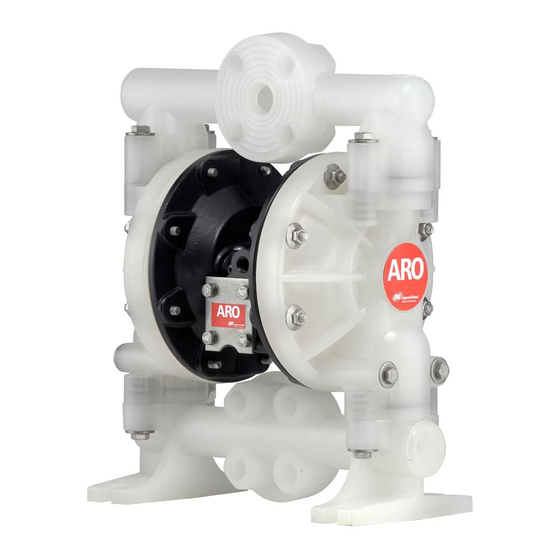
2" DIAPHRAGM PUMP
1:1 RATIO (NON-METALLIC)
OPERATING OR SERVICING THIS EQUIPMENT.
Chart for "-XXX".
Operated Double
Diaphragm
Description Chart
to 175
F (0
to 79
to 200
F (-12
to 93
. . . 77.7 dB(A)
© 2019
CCN 99443517
MODEL DESCRIPTION CHART
CENTER BODY MATERIAL
A - Aluminium
B - Cast Iron
FLUID CAP / MANIFOLD MATERIAL
3 - Polypropylene
4 - PVDF (Kynar®)
SEAT MATERIAL
2 - 316 Stainless Steel
C)
3 - Polypropylene
4 - PVDF (Kynar®)
C)
8 - 440 Stainless Steel
BALL MATERIAL
1 - Neoprene
8 - Polyurethane
2 - Nitrile
C - Hytrel®
3 - Viton®
E - Santoprene®
4 - PTFE
DIAPHRAGM MATERIAL
1 - Neoprene
4 - PTFE / Santoprene 9 - Hytrel®
2 - Nitrile
6 - Composite PTFE
3 - Viton
FLUID SECTION SERVICE KIT SELECTION
EXAMPLE: MODEL # 6662A3-321-C
FLUID SECTION SERVICE KIT # 637165-21
6662AX-X-C
RELEASED:
REVISED:
(REV: Y)
6662A3-XXX-C
Figure 1
6662 X X X X X C
B - Santoprene
6662XX X X X C
637165 X X
BALL
5-3-88
5-31-19
DIAPHRAGM
Advertisement
Table of Contents

Related Manuals for Ingersoll-Rand ARO 6662-C Series


Summary of Contents for Ingersoll-Rand ARO 6662-C Series
- Page 1 OPERATOR’S MANUAL 6662AX-X-C RELEASED: 5-3-88 INCLUDING: OPERATION, INSTALLATION AND MAINTENANCE REVISED: 5-31-19 2” DIAPHRAGM PUMP (REV: Y) 1:1 RATIO (NON-METALLIC) READ THIS MANUAL CAREFULLY BEFORE INSTALLING, OPERATING OR SERVICING THIS EQUIPMENT. It is the responsibility of the employer to place this information in the hands of the operator. Keep for future reference. SERVICE KITS 6662A3-XXX-C Refer to Model Description Chart to match the pump material...
- Page 2 OPERATING AND SAFETY PRECAUTIONS READ, UNDERSTAND, AND FOLLOW THIS INFORMATION TO AVOID INJURY AND PROPERTY DAMAGE. Safe handling practices must comply with local and EXCESSIVE AIR PRESSURE HAZARDOUS MATERIALS national laws and safety code requirements. STATIC SPARK HAZARDOUS PRESSURE Obtain Material Safety Data Sheets on all materials from the supplier for proper handling instructions.
- Page 3 GENERAL DESCRIPTION FLUID SECTION DISASSEMBLY The ARO diaphragm pump offers high volume delivery even 1. Remove top manifold(s). at low air pressure and a broad range of material compatibility 2. Remove (22) balls, (19 and 33) “O” rings and (21) seats. options available.
- Page 4 PARTS LIST / 6662AX-X-C FLUID SECTION Fluid Section Service Kits (637165-XXX OR 637165-XX) For Fluid Kits With Seats: 637165-XXX Fluid Section Service Kits include: Seats (see SEAT Option, refer to -XXX in chart below), Balls (see BALL Option, refer to -XXX in chart below), Diaphragms (see ...
- Page 5 PARTS LIST / 6662AX-X-C FLUID SECTION Torque Sequence FOR THE AIR MOTOR SECTION SEE PAGES 6 and 7 VIEW FOR -XX4 (PTFE DIAPHRAGM) CONFIGURATION ONLY PTFE Santoprene (White) (Green) Figure 2 Fluid Side TORQUE REQUIREMENTS COLOR CODE Side NOTE: DO NOT OVERTIGHTEN FASTENERS DIAPHRAGM BALL MATERIAL...
- Page 6 PARTS LIST / 6662AX-X-C AIR MOTOR SECTION Indicates parts included in 637118-C Air Section Service Kit. SERVICE KIT NOTE: Service Kit 637118-C is a general repair kit for all 1” and larger ARO diaphragm pump air motors. It contains extra O” Rings and other parts that may not be needed to service this model.
- Page 7 PARTS LIST / 6662AX-X-C AIR MOTOR SECTION IMPORTANT BE CERTAIN TO ORIENT (115) SPACER LEGS AWAY FROM BLOCKING INTERNAL PORTS WHEN REASSEMBLING AIR SECTION. MAJOR VALVE See cross section detail Figure 4. PILOT VALVE Figure 3 MAJOR VALVE CROSS SECTION DETAIL 109 110 TORQUE REQUIREMENTS NOTE: DO NOT OVERTIGHTEN FASTENERS...
- Page 8 TROUBLESHOOTING Product discharged from exhaust outlet. Low output volume, erratic flow, or no flow. Check for diaphragm rupture. Check air supply. Check tightness of diaphragm nut. Check for plugged outlet hose. Check for kinked (restrictive) outlet material hose. Check for kinked (restrictive) or collapsed inlet Air bubbles in product discharge.
Need help?
Do you have a question about the ARO 6662-C Series and is the answer not in the manual?
Questions and answers