
Subscribe to Our Youtube Channel
Related Manuals for Abicor Binzel iROB 401 AC/DC


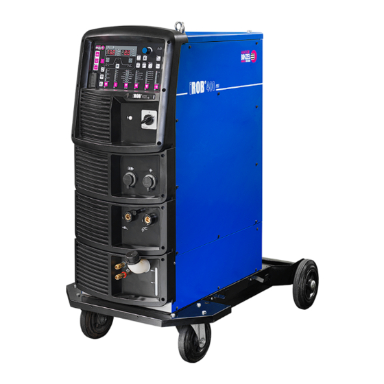
Summary of Contents for Abicor Binzel iROB 401 AC/DC
- Page 1 T E C H N O L O G Y F O R T H E W E L D E R ´ S W O R L D . EN Original operating instructions ® iROB 401 AC/DC EN Welding power source www.binzel-abicor.com...
-
Page 2: Table Of Contents
® iROB 401 AC/DC Table of contents Identification..........................EN-4 Marking .............................EN-4 Nameplate............................EN-4 Signs and symbols used ........................EN-4 Classification of the warnings ......................EN-5 Safety ..............................EN-5 Designated use..........................EN-5 Responsibilities of the user........................EN-5 Warning and information signs .......................EN-6 Safety instructions for the electrical power supply.................EN-6 Personal protective equipment......................EN-6 Emergency information........................EN-6 Scope of delivery........................EN-6... - Page 3 ® iROB 401 AC/DC 7.11.3 Fault log function..........................EN-54 7.11.4 Backup operations......................... EN-55 7.11.5 Importing backup data........................EN-56 7.12 Checking the software version...................... EN-57 Decommissioning........................EN-57 Maintenance and cleaning ....................EN-58 Maintenance and cleaning intervals ................... EN-59 Cleaning the device........................EN-59 Faults and troubleshooting ....................
-
Page 4: Identification
® 1 Identification iROB 401 AC/DC 1 Identification ® The iROB 401 AC/DC welding power source is used for automated MIG/MAG welding. The device may ® be operated only with original spare parts. These operating instructions describe the iROB 401 AC/DC welding power source only. -
Page 5: Classification Of The Warnings
® iROB 401 AC/DC 2 Safety 1.4 Classification of the warnings The warnings used in the operating instructions are divided into four different levels and shown prior to potentially dangerous work steps. Depending on the type of danger, the following signal words will be used: DANGER Describes an imminent threatening danger. -
Page 6: Warning And Information Signs
► Check the power supply cable for damage and wear at regular intervals. ► If it is necessary to replace the power supply cable, use only ABICOR BINZEL spare parts. ► Only a qualified electrician should replace the power supply cable and the mains plug. -
Page 7: Product Description
® iROB 401 AC/DC 4 Product description Returns ► Use the original packaging and packing material for returns. ► If you have questions concerning packaging and safety during shipment, contact your supplier, carrier, or transport company. 4 Product description 4.1 Structure and function ®... -
Page 8: Control Elements
® 4 Product description iROB 401 AC/DC 4.2 Control elements The control elements may vary depending on the product type. Fig. 3 Control elements A Left digital display P <Tack time> button B Right digital display Q <Arc dynamics> button C <Parameter setting>... - Page 9 ® iROB 401 AC/DC 4 Product description Tab. 1 Control elements Pos. Name Function <Parameter setting> knob Adjusts the selected parameter value (welding current, welding voltage, or wire feed speed). <Toggle welding current/wire Selects the welding current and wire feed speed. feed speed>...
- Page 10 ® 4 Product description iROB 401 AC/DC Tab. 1 Control elements Pos. Name Function <Welding procedure> Selects the desired welding procedure. selection button The selection option depends on the installed options. The LED for the selected welding procedure illuminates. Some combinations of welding wire diameter, welding wire material, welding speed, and shielding gas type are not sensible.
- Page 11 ® iROB 401 AC/DC 4 Product description Tab. 1 Control elements Pos. Name Function <Arc dynamics> button Switches the arc characteristic from soft (+10) to hard (−10). When the button is pressed, the LED illuminates and the <Parameter setting> knob can be used to adjust the parameters. The current characteristic is shown in the right digital display.
- Page 12 ® 4 Product description iROB 401 AC/DC Tab. 1 Control elements Pos. Name Function <Save> button Saves the set parameters in the job memory. 7.8 Managing the job memory on page EN-47 Imports a data backup from a USB storage device. ...
-
Page 13: Wi-Fi Router And Control App (Optional
® iROB 401 AC/DC 4 Product description 4.3 Wi-Fi router and control app (optional) Fig. 5 Wi-Fi router Wi-Fi router If the device is equipped with an optional Wi-Fi router, all device functions can also be controlled and ® programmed via the optional iROB POWER App control app. -
Page 14: Technical Data
® 4 Product description iROB 401 AC/DC 4.4 Technical data Tab. 2 Ambient conditions for transport and storage Ambient temperature −20°C to +55°C Relative humidity 20% to 80% (non-condensing) According to EN IEC 60974-1 Tab. 3 Ambient conditions for operation Ambient temperature −10°C to +40°C Relative humidity... -
Page 15: Connections
® iROB 401 AC/DC 5 Transport and installation 4.5 Connections Fig. 6 Connections on the back A Data cable for WLAN module (optional) D Welding torch control lead connection B Fieldbus interface (e.g. Ethernet IP) E MPP control lead connection C Power supply for WLAN module (optional) 5 Transport and installation WARNING... -
Page 16: Commissioning
® 6 Commissioning iROB 401 AC/DC 6 Commissioning 6.1 Establishing the power supply ► Note the safety instructions. 2.4 Safety instructions for the electrical power supply on page EN-6 WARNING Electric shock due to improperly installed electrical power supply If the electrical power supply and ground connection are improperly installed, fatal electric shocks may occur. -
Page 17: Operation
The password must be a three-digit number. "000" is not accepted as a password. ► Make a note of the password and keep it in a safe place. A forgotten password can only be reset by ABICOR BINZEL. ► To cancel password setting, set the main switch to <0>. -
Page 18: Activating The Control Panel Lock
® 7 Operation iROB 401 AC/DC Press the <Parameter selection> button. The tens digit starts to flash. Set the tens and ones digits in the same way with the <Parameter setting> knob. Check the password and press <Enter> twice. The password is saved. Activating password protection Press and hold <Enter>... -
Page 19: Overview Of Welding Parameters And Processes
® iROB 401 AC/DC 7 Operation The parameter protection function can be used to give only a selected group of persons permission to change parameters. The parameter protection function can only be canceled by entering a password. 7.1.1 Password-protecting the welding parameters on page EN-17 ►... -
Page 20: Overview Of Welding Procedures
® 7 Operation iROB 401 AC/DC 7.2.2 Overview of welding procedures The possible combinations of welding procedures are listed in the following tables and can be selected by the connected robot via the interface. If an impermissible combination is selected, this is indicated in the right/left blinking digital display <−>. -
Page 21: Preparing The Welding Process
® iROB 401 AC/DC 7 Operation 7.3 Preparing the welding process 4.2 Control elements on page EN-8 The following settings must be made before the welding process begins: Check that the welding procedure is suitable for the welding wire material to be welded. ... -
Page 22: Setting The Welding Sequence
® 7 Operation iROB 401 AC/DC 7.3.2 Setting the welding sequence Fig. 4 LED overview on page EN-12 A welding procedure consists of the following sequences: gas pre-flow, main welding parameters and gas post-flow. Depending on the end crater setting, the start welding parameter and the end crater filling parameter can be added to a sequence. - Page 23 ® iROB 401 AC/DC 7 Operation Setting the welding current Press the <Parameter selection> button repeatedly until the <Main welding parameter>, <Start welding parameter>, or <End crater filling parameter> LED illuminates. ± m/min. Verify that LED <A> (amperes) is illuminated. If it is not, press the <Toggle welding current/wire feed speed>...
-
Page 24: Effects Of The Welding Parameter Settings
® 7 Operation iROB 401 AC/DC Switching to Synergy mode Synergy Press the <Synergy mode manual ON/OFF> button. The button’s LED is on Synergy mode is active The welding voltage is automatically adjusted according to the set welding current. Arc length correction is carried out via the parameter setting. -
Page 25: Examples Of Welding Parameter Settings
® iROB 401 AC/DC 7 Operation 7.5 Examples of welding parameter settings The values shown are for guidance only. Adjust the values in line with the actual welding task and position. 7.5.1 Example of CO welding parameters Example of welding parameters with a horizontal fillet weld Tab. - Page 26 ® 7 Operation iROB 401 AC/DC Example of welding parameters with square butt welding without backing Tab. 12 Example of welding parameters with square butt welding without backing Sheet Root Wire Welding Welding Number of flow rate thickness t gap g diameter current voltage...
- Page 27 ® iROB 401 AC/DC 7 Operation Example of welding parameters with lap joints Target position Tab. 14 Example of welding parameters with lap joints Sheet Wire Welding Welding Marking diameter current voltage speed position thickness t gas flow rate (mm) (mm) (cm/min) (l/min)
-
Page 28: Example Of Welding Parameters With Mag Short Arc Welding
® 7 Operation iROB 401 AC/DC 7.5.2 Example of welding parameters with CO and flux-cored wire Example of welding parameters with fillet welds Tab. 15 Example of welding parameters with fillet welds Length l Wire diameter Welding current Arc voltage Welding speed (mm) (mm) -
Page 29: Example Of Welding Parameters With Mag Pulse Welding
® iROB 401 AC/DC 7 Operation 7.5.4 Example of welding parameters with MAG pulse welding Example of welding parameters with fillet welds Tab. 17 Example of welding parameters with fillet welds Sheet Length l Angle Number of Welding Welding thickness t (mm) of approach layers... - Page 30 ® 7 Operation iROB 401 AC/DC Example of welding parameters for welding with a back weld (semi-automatic) Tab. 20 Example of welding parameters for welding with a back weld (semi-automatic) Sheet Seam type Number of Welding Welding thickness t layers current voltage speed...
- Page 31 ® iROB 401 AC/DC 7 Operation Example of welding parameters for single pass welding (high-speed mode) Oscillation with 2 mm Oscillation time 120 times/min. Tab. 21 Example of welding parameters for single pass welding (high-speed mode) Sheet Seam type Number of Welding Arc voltage Welding...
- Page 32 ® 7 Operation iROB 401 AC/DC Example of welding parameters for multi-pass welding (standard mode) Wire diameter: 1.2 mm; shielding gas: 20% CO + Ar Tab. 22 Example of welding parameters for multi-pass welding (standard mode) Seam type Number of Welding Comments layers...
-
Page 33: Example Of Welding Parameters With Mig Pulse Aluminum Welding
® iROB 401 AC/DC 7 Operation 7.5.5 Example of welding parameters with MIG pulse aluminum welding Example of welding parameters with square butt welding Tab. 23 Example of welding parameters with square butt welding Sheet Wire Welding Welding Free thickness t diameter current voltage... -
Page 34: Additional Functions
® 7 Operation iROB 401 AC/DC 7.6 Additional functions 7.6.1 Setting the arc characteristic Use of this function makes it possible to adjust the arc from hard (−10) to soft (+10). ARC DYN. Press the <Arc control> button. The value is displayed in the left digital display. Set the arc characteristic with the <Parameter setting>... -
Page 35: Adjusting The Move Frequency
® iROB 401 AC/DC 7 Operation Use the <Parameter setting> knob to set the EN ratio. Press the <EN ratio> button to exit the menu. 7.6.3 Adjusting the move frequency The welding current switches between two values during the mX Move DC welding procedure. This creates a scaled seam surface, the markedness of which is influenced by the frequency. -
Page 36: Description Of The Internal Functions
® 7 Operation iROB 401 AC/DC 7.7.2 Description of the internal functions Some internal functions can be saved with the welding parameters. These are marked with "Yes" in the Storage option row of the tables in the descriptions. Tab. 28 Overview of internal functions No./function name Adjustable... - Page 37 ® iROB 401 AC/DC 7 Operation Tab. 28 Overview of internal functions No./function name Adjustable Starting range value F63: fine adjustment of the pulse peak current in the −150 to +150 A low pulse phase F64: fine adjustment of the pulse peak time in the low −1.5 to +1.5 ms 0 ms pulse phase...
- Page 38 ® 7 Operation iROB 401 AC/DC F5: setting the external control voltage The figure below shows the relation between the external control voltage and the output current/output voltage. These values should be used for guidance only. The real values can differ from the values shown due to line lengths and routing.
- Page 39 ® iROB 401 AC/DC 7 Operation F12: setting the run-on time for the cooling water pump (option) Adjustable range 20 to 60 min. Default value 20 min. Storage option Description Defines the run-on time for the coolant after completion of the welding process (for liquid-cooled torches).
- Page 40 ® 7 Operation iROB 401 AC/DC F17/F18: setting the backburn time/backburn voltage By setting the backburn time (F17) and backburn voltage (F18) optimally, it is possible to prevent the welding wire from adhering to the component at the end of the welding procedure. The shape of the free welding wire end can be adjusted to optimize it for the next weld start.
- Page 41 ® iROB 401 AC/DC 7 Operation F22: deactivating the button tones Deactivates the sounds when the user presses a button on the control panel. Adjustable range ON/OFF Default value Storage option Description OFF: no sounds emitted. ON: sounds emitted. F23: setting the time period until stand-by mode If the device is not used for a longer period of time, it can be automatically switched to stand-by mode.
- Page 42 ® 7 Operation iROB 401 AC/DC F38: switching on advanced welding circuit resistance measurement The arc voltage can be determined via the corresponding welding power source terminal. Use the optional arc voltage test line with a line length ≥ 30 m. Switch the direct arc voltage detection terminal to the component-side welding power source terminal or the wire feeder terminal.
- Page 43 ® iROB 401 AC/DC 7 Operation F45/F46/F47: special end crater filling sequence (Effective/Standard) Enables the time for start and end crater current to be set. Turning on the F45 function allows the weld start/end crater filling (set by the F46/F47 functions) to be executed. When the function is activated, the LED above the <Operating mode>...
- Page 44 ® 7 Operation iROB 401 AC/DC F52: DataLOG function data types This function allows the user to select data that can be saved with the DataLOG function. Tab. 29 DataLOG function data types Setting Welding Welding Welding Welding Wire feed Wire feed current current...
- Page 45 ® iROB 401 AC/DC 7 Operation When the LED is off, the fine-adjusted value is displayed. (The adjusted value is displayed in the left digital display.) When the LED is on, the absolute value is displayed. (The value adjusted from the standard value is displayed in the left digital display.) For optimal fine adjustment: To optimally adjust the pulse parameter set, the pulse peak time must first be adjusted.
- Page 46 ® 7 Operation iROB 401 AC/DC F65: fine adjustment of the base current in the low pulse phase This function allows for the fine adjustment of the base current in the mX Move DC welding procedure on the "low" side. Adjustable range −60 to +60 A Default value...
-
Page 47: Managing The Job Memory
® iROB 401 AC/DC 7 Operation F69: setting current change values (end crater parameter) The present value of the end crater parameter can be set in % based on the present value of the welding parameter Adjustable range 10 to 300% Default value 100% Storage option... -
Page 48: Changing The Job
® 7 Operation iROB 401 AC/DC 7.8.2 Changing the job Press the <Parameter selection> button. The saved values blink in the left/right digital display. Adjust the values accordingly. To change the job no., press the <Save> button. The display changes to the following status: ... -
Page 49: Deleting A Job
® iROB 401 AC/DC 7 Operation 7.8.4 Deleting a job Deleted data cannot be restored. Set the main switch to <0>. Press and hold the <Save> and <Load> buttons simultaneously and set the main switch back to <I>. Press and hold both buttons until <dEL> is displayed in the left digital display. -
Page 50: Carrying Out The Welding Process
® 7 Operation iROB 401 AC/DC 7.9 Carrying out the welding process 7.9.1 Starting the welding process Check the set welding parameters to ensure they are correct. Activate the "Welding start" signal. During welding, the welding current is displayed on the left digital display and the welding voltage is displayed on the right digital display in real time. -
Page 51: Restoring Factory Settings
The backup data on a storage device can be damaged or lost due to the influence of static electricity, impact or repair work. ABICOR BINZEL is in no way responsible for the loss or damage of electronic data or the resultant damages. -
Page 52: Welding Parameter/Internal Function Settings
® 7 Operation iROB 401 AC/DC 7.11.1 Welding parameter/internal function settings The following content can be stored in the file "BINZEL_iROB_WELDING_PARAMETER.CSV": — All welding parameters stored in the memory — The values of the internal functions at the time of the data backup The parameter set currently displayed on the control panel is not stored. - Page 53 ® iROB 401 AC/DC 7 Operation Tab. 33 Column Position Description Unit Column Position Description Unit pls_pki_adj Pulse peak current WModeTblNb Welding table no. Fine adjustment pls_pkt_adj Pulse peak time 0.1 ms chksum Checksum Checksum Fine adjustment value pls_bsi_adj Base current –...
-
Page 54: Simplified Data Log Function
® 7 Operation iROB 401 AC/DC 7.11.2 Simplified data log function The welding power source’s status can be monitored using a computer by sampling values and saving these to a USB storage device. The information is solely recorded on the connected USB storage device. The simplified data log cannot be stored as a backup. -
Page 55: Backup Operations
® iROB 401 AC/DC 7 Operation 7.11.4 Backup operations Backup data can be stored on a USB storage device. System requirements for the USB storage device: — FAT32 formatted. Set the main switch to <I>. Insert the USB storage device into the USB port on the control panel. -
Page 56: Importing Backup Data
® 7 Operation iROB 401 AC/DC 7.11.5 Importing backup data The data stored in the welding power source is overwritten by the backup data import. If necessary, save this data prior to conducting the import. Set the main switch to <I>. Insert the USB storage device into the USB port on the control panel. -
Page 57: Checking The Software Version
® iROB 401 AC/DC 8 Decommissioning 7.12 Checking the software version Fig. 13 Checking the software version A Product C Sub-version B Main version D Upgrade version P## ### Ver. ### ### ### ### Tab. 34 Software version display Indicator Display content Left digital display Right digital display... - Page 58 ® 9 Maintenance and cleaning iROB 401 AC/DC 9 Maintenance and cleaning Scheduled maintenance and cleaning are prerequisites for a long service life and trouble-free operation. The maintenance cycle is determined by the work environment and the device’s maintenance intervals. If the device is operated for more than 8 hours a day, the maintenance intervals should be changed as needed.
-
Page 59: Maintenance And Cleaning
® iROB 401 AC/DC 9 Maintenance and cleaning 9.1 Maintenance and cleaning intervals The specified intervals are standard values and refer to single-shift operation. We recommend recording the inspections. The date of the inspection, the detected defects and the name of the inspector must be recorded. Daily ►... -
Page 60: Faults And Troubleshooting
10 Faults and troubleshooting iROB 401 AC/DC 10 Faults and troubleshooting ► Observe the documentation for the welding components. ► Contact your retailer or ABICOR BINZEL in the event of questions or problems. 10.1 General faults Tab. 35 General faults and troubleshooting Fault... -
Page 61: Faults On The Control Panel
® iROB 401 AC/DC 10 Faults and troubleshooting Tab. 35 General faults and troubleshooting Fault Cause Troubleshooting The WCR signal is permanently WCR relay of the welding power source is ► Have printed circuit board PCB2 replaced. present on the robot. defective. - Page 62 ® 10 Faults and troubleshooting iROB 401 AC/DC Tab. 36 Fault codes on the control panel and their remedy Fault code Type of fault Cause of fault Measure 1 = alarm 2 = warning Fault in the control voltage. ► If the welding power source is connected to other devices, check all connection lines for abnormalities (e.g.
- Page 63 ® iROB 401 AC/DC 10 Faults and troubleshooting Tab. 36 Fault codes on the control panel and their remedy Fault code Type of fault Cause of fault Measure 1 = alarm 2 = warning Excess current has been detected ► Check that the contact pipe at the end of the torch is not on the output side of the welding touching the component.
-
Page 64: Disassembly
► Observe the relevant local regulations and disposal instructions in the safety data sheets specified by the manufacturer of the consumables. 12.3 Packaging ABICOR BINZEL has reduced the transport packaging to the necessary minimum. The ability to recycle packaging materials is always considered during their selection. EN - 64... -
Page 65: Ifr-800 Fieldbus Connection Tool
® iROB 401 AC/DC 13 IFR-800 fieldbus connection tool 13 IFR-800 fieldbus connection tool 13.1 Configuration The fieldbus connection tool complies with the following communication standards. The type of fieldbus connection tool depends in each case on the communication standard used. Tab. - Page 66 ® 13 IFR-800 fieldbus connection tool iROB 401 AC/DC PROFIBUS Tab. 39 PROFIBUS basic properties Communication standard PROFIBUS-DP Baud rate (speed) Support of all common baud rates up to 12 MBit/s (automatic detection) Connector IEC 61076-2-101, M12, 5-pole, B-coded, socket Node address Default setting: 77 The setting can be made with the configuration switch from...
- Page 67 ® iROB 401 AC/DC 13 IFR-800 fieldbus connection tool PROFINET IRT Tab. 41 PROFINET IRT basic properties Communication standard PROFINET IRT Bandwidth 10/100 MBit/s Connector IEC 61076-2-101, M12, 4-pole, D-coded, socket IP address Default setting: 192.168.0.2 To change the IP address, a workstation computer on which special software is installed must be connected to the welding power source via Ethernet.
-
Page 68: Processing Time For Communication Data
® 13 IFR-800 fieldbus connection tool iROB 401 AC/DC Modbus-TCP Tab. 42 Modbus-TCP basic properties Communication standard Modbus-TCP Bandwidth 10/100 MBit/s Connector IEC 61076-2-101, M12, 4-pole, D-coded, socket IP address Default setting: 192.168.0.2 The IP address can be changed by means of a workstation computer and corresponding software via the Ethernet interface. -
Page 69: List Of I/O Data
® iROB 401 AC/DC 13 IFR-800 fieldbus connection tool 13.4.1 List of I/O data Tab. 43 List of output data Byte Bit 7 Bit 6 Bit 5 Bit 4 Bit 3 Bit 2 Bit 1 Bit 0 Watchdog – – Weld Shielding gas Wire... - Page 70 ® 13 IFR-800 fieldbus connection tool iROB 401 AC/DC Tab. 44 List of input data Byte Bit 7 Bit 6 Bit 5 Bit 4 Bit 3 Bit 2 Bit 1 Bit 0 Watchdog Weld Shielding gas Wire Wire Weld detection rinsing retraction feed...
-
Page 71: Simplified Table For Output Data
® iROB 401 AC/DC 13 IFR-800 fieldbus connection tool Working with integers In the data lists, the following data format is used for integer data such as "16-bit signed integer": Bit order and byte order are illustrated in the following example (general little-endian system). Example: The setting for 350 (decimal) = 0 ×... - Page 72 ® 13 IFR-800 fieldbus connection tool iROB 401 AC/DC Tab. 45 Simplified table for output data Offset Function Description Setting for 1: setting for wire feed speed 0: welding current setting Wire feed speed Setting for wire feed 1: valid 0: invalid speed 9–10...
-
Page 73: Example Of Setting Output Data
® iROB 401 AC/DC 13 IFR-800 fieldbus connection tool 13.4.3 Example of setting output data The following example illustrates the setting method for replacing the individual operations in the device with transmission data (output data) from an external device. Tab. 46 Example of setting output data Operation Setting method... -
Page 74: Details Of I/O Data
® 13 IFR-800 fieldbus connection tool iROB 401 AC/DC 13.4.4 Details of I/O data Tab. 47 Details of output data Byte Function Description Weld start The value 1 signals that the welding start mode is active. Has no effect when wire feed or wire retraction are performed. - Page 75 ® iROB 401 AC/DC 13 IFR-800 fieldbus connection tool Tab. 47 Details of output data Byte Function Description Load job memory Setting "Load job memory" to 1 loads the welding condition of the number that is set as the save location number.
- Page 76 ® 13 IFR-800 fieldbus connection tool iROB 401 AC/DC Tab. 47 Details of output data Byte Function Description – Arc characteristic Specifies the arc characteristic. 7.6.1 Setting the arc characteristic on page EN-34 – En ratio Specifies the En ratio. The unit for this setting is [%]. The En ratio is the ratio between the negative and positive polarized part of the electrode during AC welding.
- Page 77 ® iROB 401 AC/DC 13 IFR-800 fieldbus connection tool Tab. 47 Details of output data Byte Function Description 0–6 Function (port 1) no. Settings other than offsets 4 to 17 are specified here. There are 4 setting ports, so up to 4 settings can be Function (port 1) changed at the same time.
- Page 78 ® 13 IFR-800 fieldbus connection tool iROB 401 AC/DC Tab. 52 Setting the welding wire material Setting Welding wire material Fe (flux-cored wire) CrNi CrNi (Ferr) CrNi (flux-cored wire) AlMg5 AlSi5/12 CuSi CuAl Ni base Tab. 53 Setting the welding wire diameter Setting Welding wire diameter [mm] Tab.
- Page 79 ® iROB 401 AC/DC 13 IFR-800 fieldbus connection tool Tab. 55 Details of input data Offset Function Description Warning Becomes 1 if a warning is issued. A warning is different from a fault because operation of the device is not stopped. Fault Becomes 1 if a fault is issued.
-
Page 80: Functions
® 13 IFR-800 fieldbus connection tool iROB 401 AC/DC Tab. 56 Fault code Fault code Description No fault or "Acknowledge operation stop/fault" is in effect. 1–999 This value corresponds to the "E ***" fault codes. Tab. 36 Fault codes on the control panel and their remedy on page EN-61 1001 Watchdog fault 1002... - Page 81 ® iROB 401 AC/DC 13 IFR-800 fieldbus connection tool Tab. 57 Function numbers Function name Adjustable Specified Description range value Determine wire feed load – – The measured value for the wire feed load can be determined using input data. The value is expressed as a percentage [%] of the nominal load.
-
Page 82: Control Timing
® 13 IFR-800 fieldbus connection tool iROB 401 AC/DC 13.4.6 Control timing Shielding gas pre-flow/shielding gas post-flow The timing for weld start and the shielding gas pre-flow/post-flow normally corresponds to the timing described if no end crater is set. However, if shielding gas rinsing was activated before the weld start and the weld start is activated without deactivating shielding gas rinsing, the pre-flow period is omitted and the voltage is immediately present at the output. -
Page 83: Accessories
® iROB 401 AC/DC 14 Accessories 14 Accessories Tab. 58 Accessories Item description Order number Wi-Fi router 890.0603.1 Expansion board for Wi-Fi router 890.0624.1 Connection lead for Wi-Fi router 890.0747.1 Wire feeder iFEED 742 890.0746.1 Fieldbus module Profibus (PB) 890.0743.1 Fieldbus module ProfiNet (PN) 890.0744.1 Fieldbus module DeviceNet (DN) - Page 84 Follow step 1 on the landing Open the app. Then scan the page of the ABICOR BINZEL page and install the free of QR code of the ABICOR BINZEL web site. charge TechCommApp. channel using the QR code scanner you find in the app.
Need help?
Do you have a question about the iROB 401 AC/DC and is the answer not in the manual?
Questions and answers