Table of Contents
Advertisement
Quick Links
Advertisement
Table of Contents

Related Manuals for Major tech MT775


Summary of Contents for Major tech MT775
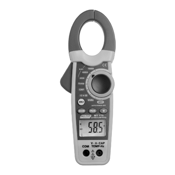
- Page 1 INSTRUCTION MANUAL MT775 AC/DC TRMS CLAMP METER...
-
Page 3: Table Of Contents
Contents Page no 1. Safety ..................4 2. Description ................5 2.1. Meter Description .............. 5 2.2. Symbols Used on LCD Display ...........6 3. Specifications ................ 7 3.1. Specifications ..............7 3.2. General Specifications ............9 4. Operation ................10 4.1. -
Page 4: Safety
1. Safety 1.1. lnternational Safety Symbols This symbol, adjacent to another symbol or terminal, indicates the user must refer to the manual for further information. This symbol, adjacent to a terminal, indicates that, under normal use, hazardous voltages may be present. Double insulation. -
Page 5: Description
• If the equipment is used in a manner not specified by the manufacturer, the protection provided by the equipment may be impaired. 2. Input Limits Function Maximum Input A AC/DC 1000A V AC/DC 1000V DC/AC Frequency, Resistance, 1000V DC/AC Diode, Continuity, Capacitance Test 1000V DC/ AC... -
Page 6: Symbols Used On Lcd Display
2.2. Symbols Used on LCD Display Low Impedance Input Mode DC (Direct Current) Minus Sign AC (Alternating Current) Low Battery Inrush Current Mode Auto Power Off Auto Range Mode Diode Test Mode 10. Audible Continuity 11. Peak Voltage Value 12. Relative Mode 13. -
Page 7: Specifications
3. Specifications 3.1. Specifications Function Range & Resolution Accuracy ±(% of reading+digits) 600.0A ±(2.5% + 8 digits) AC Current (50/60Hz) 1000A ±(2.8% + 8 digits) ±(2.5% + 5 digits) DC Current 600.0A 1000V ±(2.8% + 5 digits) Over range protection: Maximum input 1000A. Accuracy specified from 5% to 100% of the measuring range. - Page 8 Function Range & Resolution Accuracy ±(% of reading+digits) Resistance 600.0Ω ±(1.0% + 4 digits) 6.000KΩ 60.00KΩ ±(1.5% + 2 digits) 600.0KΩ 6.000MΩ ±(2.5% + 3 digits) 60.00MΩ ±(3.5% + 5 digits) Input Protection: 300V DC or 300V AC RMS. Function Range &...
-
Page 9: General Specifications
3.2. General Specifications Clamp Size 33mm approx TRMS The AC voltage and AC current of this instrument are measured by TRMS. True RMS measurement is different from mean measurement. The mean measurement method can only measure the symmetric waveform, such as sine wave. True RMS measurements can reliably measure any irregular waveform and obtain valid values for AC voltage or AC current. -
Page 10: Operation
4. Operation NOTICES: Read and understand all warning and precaution statements listed in the safety section of this operation manual prior to using this meter. Set the function select switch to the OFF position when the meter is not in use. 4.1. -
Page 11: Ac/Dc Voltage Measurement
4.2. AC/DC Voltage Measurements 1. Insert the black test lead into the negative COM terminal and the red test lead into the positive V terminal. 2. Set the function switch to the ACV or DCV position. 3. Connect the test leads in parallel to the circuit under test. 4. -
Page 12: Capacitance Measurements
4.5. Capacitance Measurements WARNING: To avoid electric shock, disconnect power to the unit under test and discharge all capacitors before taking any capacitance measurements. Remove the batteries and unplug the line cords. 1. Set the rotary function switch to the Ω CAP position. -
Page 13: Non-Contact Ac Voltage Measurements
4.8. Non-Contact AC Voltage Measurements WARNING: Risk of Electrocution. Before use, always test the Voltage Detector on a known live circuit to verify proper operation 1. Touch the probe tip to the live conductor or insert into the live side of the electrical outlet. -
Page 14: Rel/Backlight Button
5.4. REL /Backlight Button REL for DCA and Capacitance Zero & Offset adjustment. Hold down this button to turn the backlight ON and OFF. 5.5. Data Hold / Flashlight Button 1. To freeze the LCD meter reading, press the data hold button. The data hold button is located on the right side of the meter (top button). - Page 16 MAJOR TECH (PTY) LTD T9 Industrial Village, Sam Green Road, Telephone: +27 11 8 2 7 5500 Tunney Ext. 9, Elandsfontein National Contact Number: 08 61 62 5678 South Africa E-mail: sales@major-tech.com P .O. Box 888, Isando 1600, South Africa...
Need help?
Do you have a question about the MT775 and is the answer not in the manual?
Questions and answers