Makita VC2211M Technical Information
Hide thumbs
Also See for VC2211M:
- Instruction manual (84 pages) ,
- Instruction manual (77 pages) ,
- Instruction manual (13 pages)
Advertisement
Quick Links
T
ECHNICAL INFORMATION
Model No.
Description
C
ONCEPT AND MAIN APPLICATIONS
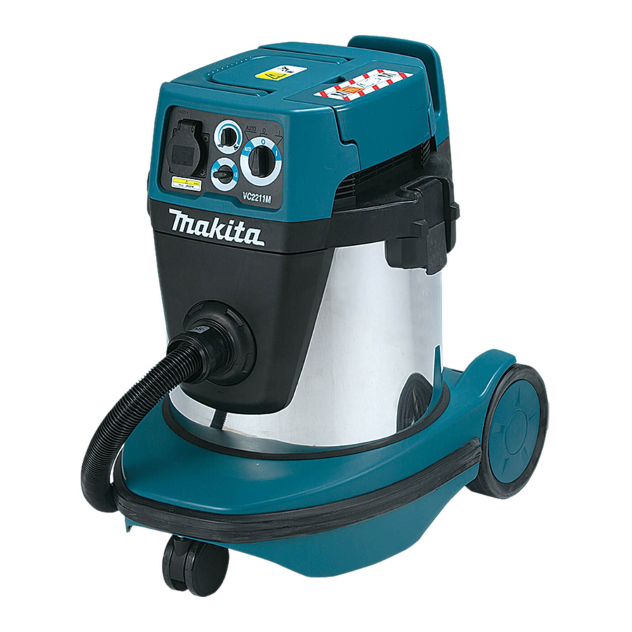
Model VC2211M is a Wet & Dry vacuum cleaner developed
based on Model VC3211M.
This model is approved for Dust Class M in accordance with
the EU standard.
Its main features are:
• High maneuverability and easy mobility thanks to 22 Liter compact
stainless steel tank
• New automatic self-cleaning filtration system of our unique design
• Power tool activation
S
pecification
Voltage (V)
230
240
Wet/Dry type
Power tool activation
Dust class in accordance with the EU standard
Max sealed suction: kPa
Max air flow: m³/minute
Tank capacity: L
Noise level: dB (A)
Variable suction power control by dial
Protection from electric shock
Power supply cord: m (ft)
Weight according to EPTA-Procedure 01/2003*
*1 With Hose complete 28-3.5
*2 With Hose complete 38-2.5
*3 With Poly bag 800x650
S
tandard equipment
Hose complete 28-3.5 set
Front cuff 22
Front cuff 24
Front cuff 38
Belt hook
Hose band
Cap
Poly bag 800x650
Poly bag set
(incl. 10 pcs of Poly bag 800x650)
Note: The standard equipment may vary by country or model variation.
VC2211M
Vacuum Cleaner
Current (A)
Cycle (Hz)
4.8
50/60
4.6
50/60
Water
Dust
3
Continuous Rating (W)
Input
1,050
1,050
Wet & Dry
2.0*
Grounding
5.0 (16.4)
: kg (lbs)
16.3 (35.9)
O
Hose complete 28-2.5/ 28-3.5/
Front cuff 22/ 24/ 38
Filter bag set
Poly bag set
Powder filter, Damper, Prefilter
Straight pipe, Bending pipe, Nozzle assembly,
Corner nozzle, Anchor nozzle, Round brush,
Cap, Cleaning set, Nozzle for wet application,
Belt hook, Hose band
W
Dimensions: mm (")
Length (L)
Width (W)
Height (H)
Max Output (W)
Output
---
---
Yes
M
22.0
/ 3.5*
1
2
17
22
73
Yes
ptional accessories
28-5.0/ 38-2.5/ 38-5.0
OFFICIAL USE
for ASC & Sales Shop
August 2016
P 1/ 21
H
L
552 (21-3/4)
398 (15-5/8)
569 (22-3/8)
---
---
Advertisement

Related Manuals for Makita VC2211M


Summary of Contents for Makita VC2211M
- Page 1 VC2211M Description Vacuum Cleaner ONCEPT AND MAIN APPLICATIONS Model VC2211M is a Wet & Dry vacuum cleaner developed based on Model VC3211M. This model is approved for Dust Class M in accordance with the EU standard. Its main features are: •...
-
Page 2: Necessary Repairing Tools
M5x60 Pan head screws through Endbell and Field into Base [2] LUBRICANT/ADHESIVE APPLICATION Apply Makita grease FA No.2 to the following portions designated by black triangle to protect parts and product from unusual abrasion.. (Fig.1) Apply ThreeBond 1215 to Rubber ring 120 and Seal ring. - Page 3 P 3/ 21 epair [3] DISASSEMBLY/ ASSEMBLY [3]-1. Motor section DISASSEMBLING (1) Unlock two hooks to separate Motor section from Tank section. (Fig. 2) (2) Raise Grip and open Base hook, then remove nine 4x35 Tapping screws to remove Base grip and Cowling complete from Separator complete.
- Page 4 P 4/ 21 epair [3] DISASSEMBLY/ ASSEMBLY [3]-1. Motor section (cont.) DISASSEMBLING (7) Take two Closed end splices (Connector 2-SD) out of the splice storage compartment to allow the lead wire of each of two Lead units to have slack in it. (Fig. 7) (8) With the lead wire of Lead units slack, remove Separator complete from Tank cover complete.
- Page 5 P 5/ 21 epair [3] DISASSEMBLY/ ASSEMBLY [3]-1. Motor section (cont.) DISASSEMBLING (10) Disconnect Carbon brushes from the commutator of Armature assembly by moving the tail end of the spiral spring of each Brush holder as shown in Fig. 10. Note: No need to remove Carbon brushes in this step.
- Page 6 P 6/ 21 epair [3] DISASSEMBLY/ ASSEMBLY [3]-1. Motor section (cont.) ASSEMBLING (1) Assemble the parts shown in Fig. 14. Note: Loosely tighten M8 Hex nut to Armature shaft. (2) Install Fan cover onto the assembly you made in step (1) as follows: 1.
- Page 7 P 7/ 21 epair [3] DISASSEMBLY/ ASSEMBLY [3]-1. Motor section (cont.) ASSEMBLING (5) Make sure that Wave washer 20 is placed in the bearing chamber of Endbell, insert Armature assembly into Endbell. (6) While pressing the bearing chamber of Endbell straight down so that Wave washer 20 is approximately level, alternately tighten the two M5x60 Pan head screws with a manual screwdriver until they are seated.
- Page 8 Note: Do not forget to place DC motor seal between Separator complete on Tank cover complete. Note: Apply Makita grease FA No.2 to the gear chamber of Gear case to prevent Spindle assembly from falling off from DC motor unit.
- Page 9 P 9/ 21 epair [3] DISASSEMBLY/ ASSEMBLY [3]-2. Inner cover DISASSEMBLING (1) Turn the assembly of Inner cover and Tank cover complete upside down, then raise Lock lever to remove two Pre-filters. (Fig. 25) (2) Remove eight 4x35 Tapping screws that fasten Inner cover to Tank cover complete. (Fig. 26) Three of the eight screws are used also to fasten Protector to Inner cover.
- Page 10 P 10/ 21 epair [3] DISASSEMBLY/ ASSEMBLY [3]-2. Inner cover (cont.) ASSEMBLING Assemble by reversing the disassembly procedure. Note: • When installing Seal ring onto Tank cover complete, put the protruding portion of the ring in the depressed portion of Tank cover complete, then apply ThreeBond 1215 to the portion as shown on the left of Fig.
- Page 11 2. Put 1R275 in the groove of the plastic portion of new Caster 75. 3. Hit 1R275 with a plastic hammer. *You can use any kind of grease such as Makita grease FA No.2. Caster 75 1R275 plastic portion of new Caster 75...
- Page 12 P 12/ 21 epair [3] DISASSEMBLY/ ASSEMBLY [3]-5. Bumper Fig. 36 DISASSEMBLING Pry Bumper off from Tank with a slotted screwdriver. (Fig. 36) ASSEMBLING Assemble by reversing the disassembly procedure. Note: Make sure that there is no gap between Bumper and Base. Bumper Tank [3]-6.
-
Page 13: Circuit Diagram
P 13/ 21 ircuit diagram Fig. D-1 Motor assembly Color index of lead wires' sheath Black Blue Straight terminal with lock 16 AWG White Purple (#187, t=0.8) of Field assembly Gray Brush holder Yellow Green Field Orange Brush holder DC motor Varnished Flag terminal without lock polyester tube... - Page 14 P 14/ 21 ircuit diagram Fig. D-2 Receptacle Country Back view Part No. Front view showing where Terminals C1, C2 and C3 are located C03 to Green and Yellow wire C01 to C02 to European countries, 655117-0 Orange wire Purple wire etc.
-
Page 15: Wiring Diagram
P 15/ 21 iring diagram 1. AC motor unit Fig. D-3 AC motor unit, Field lead wire viewed from top to Controller Fix two Field lead wires to each Brush holder in these lead wire holders. Brush holder Brush holder Field lead wire to Controller Fig. - Page 16 P 16/ 21 iring diagram 1. AC motor unit (cont.) Fig. D-6 Be careful not to pinch the pig tail wire AC motor unit of Carbon brush between Motor cover Motor cover and Brush holder. pig tail wire of Carbon brush Brush holder Fig.
- Page 17 P 17/ 21 iring diagram 2. Wiring in Separator complete Fig. D-8 Put the following Lead wires between these ribs: • Power supply cord lead wire connected to Controller • Controller lead wires connected to DC motor • Buzzer circuit lead wires •...
- Page 18 P 18/ 21 iring diagram 2. Wiring in Separator complete Fig. D-9 Do not place the slack of Lead wires Do not place the slack of Lead wires on this portion. on these ribs. Place Lead wires and Vinyl tube between the boss and the inside wall boss...
- Page 19 Testing Air velocity sensor P 19/ 21 Check, as described below, whether air velocity sensor works normally. Necessary tools Pressure gauge: One able to measure more than -20kPa negative pressure (The pressure should be shown in 0.1kPa.) Plastic board: To block the hose connection port How to test Assemble the machine body to Tank after removing Filters.
- Page 20 Turn on the power and the machine will start suctioning. P 20/ 21 Gradually block the hose connection port with a plastic board, and then check whether Buzzer beeps at a pressure level between -12.8 and - 9.6kPa. Detailed explanation Block the hose connection port with a plastic board so that the pressure reads about between -12.0 and -11.5kPa.
- Page 21 (b) Check whether the boss hole is clogged. P 21/ 21 If clogged, completely remove dust/debris. (c) If Buzzer does not beep even after following the above solutions, Buzzer circuit may be broken. So replace it with a new one. (d) If Buzzer still does not sound even after Buzzer circuit has been replaced, Controller may be broken.
Need help?
Do you have a question about the VC2211M and is the answer not in the manual?
Questions and answers