
Related Manuals for Clarke PG9500ADVES


Summary of Contents for Clarke PG9500ADVES
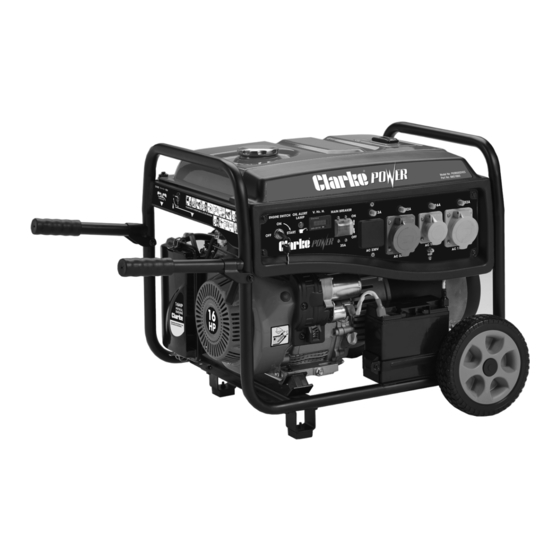
- Page 1 8.5KVA PETROL GENERATOR MODEL NO: PG9500ADVES PART NO: 8857860 OPERATION & MAINTENANCE INSTRUCTIONS DL0623...
-
Page 2: Environmental Recycling Policy
Should any loss or damage be apparent, please contact your CLARKE dealer immediately. GUARANTEE This CLARKE product is guaranteed against faulty manufacture for a period of 12 months from the date of purchase. Please keep your receipt as proof of purchase. -
Page 3: Specifications
SPECIFICATIONS CLARKE part no 8857860 PG9500ADVES Engine Engine Model SC460 Engine Power 16HP - 10.5kW Fuel Type E10 Unleaded Petrol (87 Octane Rate) Displacement (cc) Starting system Electric & Hand Recoil Fuel tank capacity (Litre) 20 L (Safe Capacity) Fuel consumption 3.3 L/Hr... -
Page 4: Safety Symbols
GENERAL SAFETY RULES & SYMBOLS SAFETY SYMBOLS Read Instruction manual DANGER - highly before use flammable liquid. Caution - The user should Engine and exhaust be aware of a general become hot during use hazard - DO NOT touch Dangerous voltage. Risk Poisonous fumes - DO of electric shock NOT use in an enclosed... -
Page 5: Work Area
WORK AREA 1. ALWAYS use in a well ventilated area. 2. ALWAYS position the exhaust outlet away from people. 3. NEVER use indoors or in a confined space. 4. ALWAYS keep children away from the generator. POSITIONING THE GENERATOR 1. ONLY use the folding handles to wheel the generator into position. NEVER use them to lift the generator off the ground. - Page 6 3. NEVER use water or any other liquid to clean the generator. 4. ALWAYS ground the generator before using it to maximise safety, see ‘Ground The Generator’ section on page 14. 5. ALWAYS use a ground fault circuit interrupter (GFCI) (not included) in highly conductive areas such as metal decking or steel work.
-
Page 7: Generator Overview
GENERATOR OVERVIEW NO DESCRIPTION NO DESCRIPTION Control Panel Folding Handles Battery Fuel Cap Oil Fill Cap/Dipstick Fuel Gauge Oil Drain Plug 10 Choke Recoil Starter 11 Spark Plug Air Filter 12 Muffler/Exhaust Parts & Service: 020 8988 7400 / E-mail: Parts@clarkeinternational.com or Service@clarkeinternational.com... -
Page 8: Control Panel Overview
CONTROL PANEL OVERVIEW NO DESCRIPTION NO DESCRIPTION Electric Start Ignition 32A, 240V Plug Socket Oil Level Alert Lamp 16A Breaker Switch Data Centre (Volts & Hertz per 10 16A, 110V Plug Socket hour) Main Breaker Switch 11 Earth Grounding Terminal 13A Breaker Switch 12 32A Breaker Switch AC 230V Plug Socket... -
Page 9: Before Using The Generator
UNPACKING Unpack your generator and check to ensure the following items are present. Should there be any deficiency or damage caused during transit contact your CLARKE dealer immediately. 1 x 8.5kW Petrol Generator 2 x Folding Handle c/w fixings 2 x Axle, Washer & R Clip 1 x Spark Plug Box Spanner &... -
Page 10: Fitting The Wheels
ASSEMBLY CAUTION: DUE TO THE WEIGHT OF THE GENERATOR, IT IS RECOMMENDED THAT THE ASSEMBLY IS UNDERTAKEN BY 2 PERSONS. FITTING THE WHEELS 1. Slide the axle through the wheel and place the washer on the axle on the frame side of the wheel. -
Page 11: Connecting The Battery
FITTING THE FOLDING HANDLES 1. Insert the rubber block in the end of the handle with the hinge bracket. 2. Fit the hinge bracket to the generator frame and secure with M8 washers, nut and bolt. 3. Slide the handle grip onto the end of the handle. -
Page 12: Preparation Before Operation
PREPARATION BEFORE OPERATION ADDING ENGINE OIL WARNING: THIS GENERATOR IS SOLD WITHOUT OIL INCLUDED. DO NOT ATTEMPT START THE GENERATOR WITHOUT INSTALLING THE CORRECT OIL FIRST. Always check and add the correct engine oil before starting the generator. DO NOT use any special additives. -
Page 13: Adding Fuel
ADDING FUEL RECOMMENDED FUEL: Only use standard unleaded petrol. DO NOT mix with oil. 1. Check the fuel level on the fuel gauge. The fuel gauge will show as red when you have fuel in the tank turning white as the fuel level decreases. -
Page 14: Ground The Generator
GROUND THE GENERATOR WARNING: TO REDUCE THE RISK OF ELECTRIC SHOCK AND TO MAXIMISE SAFETY, THE GENERATOR SHOULD BE PROPERLY GROUNDED BEFORE USE. Ground the generator by tightening the earth grounding terminal on the front control panel against a grounding wire. A generally acceptable grounding wire is a No. - Page 15 3. Move the Engine Choke Lever to the ‘CHOKE’ position. FOR ELECTRIC START 1. Insert the key into the ignition. 2. Turn and hold key in the start switch to the ‘Start’ position until the generator starts. NOTE: To prolong the life of the starter components, DO NOT hold the key in the ‘Start’...
-
Page 16: Connecting Electrical Devices
FOR MANUAL RECOIL START 1. Firmly grasp the recoil starter handle and pull slowly until increased resistant is felt. 2. Then pull rapidly up. 3. Once the engine has started, move the choke lever to 1/2 CHOKE position until engine runs smoothly and then fully to the ‘RUN’... - Page 17 total starting (max.) watts can be estimated by adding only the items with the highest additional starting (max.) to the total rated watts. Example only: Tool/Appliance Running Watts Additional Starting Watts Refrigerator 1350 Portable Fan Laptop 46 in. Flat Screen TV Light (75 Watts) 1255 Total Running Watts 1350 Highest Starting Watts Total Running Watts:...
-
Page 18: Shutting Down The Generator
The chart below serves as a reference only for the estimated wattage requirements of common electrical devices. However, DO NOT solely reply on this chart as all appliances are built differently, ALWAYS check the wattage listed on the electrical device before consulting this chart: Tool/Appliance Rated (Running) Watts Surge (Starting) Watts Hot Plate... -
Page 19: Maintenance And Troubleshooting
Proper routine maintenance of the generator will help prolong the life of the machine. Please perform maintenance checks and operations according to the Maintenance Schedule below. If there are any questions about the maintenance procedures listed in this manual, please contact the CLARKE service centre. WARNING: NEVER PERFORM MAINTENANCE OPERATIONS WHILE THE GENERATOR IS RUNNING. -
Page 20: Generator Maintenance
• Change engine oil (see page 21) Yearly • Replace engine air filter (see page 23) • Service fuel valve • Clean and service spark plug and replace if necessary (see page • Inspect muffler (exhaust) and spark arrester (see page 23) •... -
Page 21: Changing The Oil
CHANGING THE OIL Change the oil after the first 5 hours of operation, then every 50 hours thereafter. If running this unit under dirty or dusty conditions, or in extremely hot weather, change the oil more often. WARNING: HOT OIL MAY CAUSE BURNS. ALLOW THE ENGINE TO COOL BEFORE DRAINING THE OIL. - Page 22 INSPECTING OR REPLACING THE SPARK PLUG Use spark plug F6TC, BPR4ES or equivalent. Replace the spark plug once every year. This will help the engine start easier and run better. 1. Make sure the generator is off and remove the spark plug wire. 2.
- Page 23 • If the air filter element has been damaged, replace it with a new one. Contact the CLARKE service centre. 4. Reinstall the air filter element within the casing and reinstall the air filter cover.
-
Page 24: Troubleshooting
Drain fuel. Refuel with fresh treating or draining petrol, or petrol (see page 25-26) refueled with bad petrol Dirty fuel filter Replace fuel filter or contact the CLARKE service department (see page 13) Engine lacks Dirty air filter Check air filter element. power... -
Page 25: Draining The Fuel System
(if used) Item plugged in is defective Try a different device. If this does not solve your problem contact the CLARKE service department. STORAGE The generator should be started at least once every seven days and be allowed to run for at least 30 minutes. If this can’t be done and the unit must be stored for more than 30 days, use the following information as a guide to prepare it for storage. - Page 26 • Unscrew the fuel drain plug. • Turn the fuel switch to the ‘ON’ position to open the drain. • Once the fuel has drained, replace the drain plug and turn the fuel switch to the ‘OFF’ position. 2. Start and run the engine until the engine stops from lack of fuel. 3.
- Page 27 11. If it is not practical to empty the fuel tank and the unit is to be stored for some time, use a commercially available fuel stabiliser added to the petrol to increase the life of the petrol. CLARKE GENERATOR ACCESSORIES Extension Lead - EL16 Generator Plug -...
- Page 28 ALTERNATOR DIAGRAM Description Description Alternator Assembly Voltage Regulator Rotor Wiring Board Stator Flat Washer Plain Washer Spring Washer Rotor Bar Alternator Bracket Carbon Brush Flange Bolt Flange Bolt Flange Bolt Flange Bolt Lock Nut Alternator End Cover Parts & Service: 020 8988 7400 / E-mail: Parts@clarkeinternational.com or Service@clarkeinternational.com...
-
Page 29: Engine Diagram
ENGINE DIAGRAM Description Description Bolt, M6 x 60 Bolt, Stud, Intake Cover Comp. Head Bolt, Stud, Exhaust Gasket, Head Cover Cylinder Head Compartment Breather Tube Spark Plug Bolt, M6 x 12 Head Gasket, Cylinder Cover Dowel Pin Bolt, M10 x 87 Parts &... -
Page 30: Frame Diagram
FRAME DIAGRAM Parts & Service: 020 8988 7400 / E-mail: Parts@clarkeinternational.com or Service@clarkeinternational.com... - Page 31 Description Description Handlebar Rubber Cover Vibration Absorber Rear Handlebar Arm Flange Nut Handlebar Plastic Plug Ground Terminal Flange Bolt Vibration Absorber Washer Flange Bolt Flange Bolt Washer Support Flange Nut Flange Nut Axle Flange Nut Flat Washer Flange Bolt Wheel Assembly Flange Bolt R- Clip, Dowel Pin Vibration Absorber Front...
- Page 32 FUEL TANK DIAGRAM Description Description Fuel Tank Cap Bushing Fuel Filter Fuel Tank Rubber Mat Fuel Level Gauge Fuel Valve Flange Bolt Clamp Fuel Tank Washer Fuel Pipe Parts & Service: 020 8988 7400 / E-mail: Parts@clarkeinternational.com or Service@clarkeinternational.com...
- Page 33 MUFFLER/EXHAUST DIAGRAM Description Description Support Bracket Spring Washer Flange Bolt Hex Nut Flange Bolt Muffler Washer Flange Nut Flange Nut Air Cleaner Bracket Muffler Gasket Parts & Service: 020 8988 7400 / E-mail: Parts@clarkeinternational.com or Service@clarkeinternational.com...
- Page 34 DECLARATION OF CONFORMITY - UKCA Parts & Service: 020 8988 7400 / E-mail: Parts@clarkeinternational.com or Service@clarkeinternational.com...
-
Page 35: Declaration Of Conformity (Ce)
DECLARATION OF CONFORMITY - CE Parts & Service: 020 8988 7400 / E-mail: Parts@clarkeinternational.com or Service@clarkeinternational.com... - Page 36 Parts & Service: 020 8988 7400 / E-mail: Parts@clarkeinternational.com or Service@clarkeinternational.com...
Need help?
Do you have a question about the PG9500ADVES and is the answer not in the manual?
Questions and answers