Escea DN1150 Corner 400 Installation & Service Instructions Manual
Hide thumbs
Also See for DN1150 Corner 400:
- Information sheet for builders and architects (2 pages) ,
- Installation & service instructions manual (59 pages)

Subscribe to Our Youtube Channel
Related Manuals for Escea DN1150 Corner 400


Summary of Contents for Escea DN1150 Corner 400
- Page 1 DN1150 LH-RH Corner 400 GAS FIREPLACE Installation & Service Instructions 630719_5...
- Page 2 The heater must be installed according to these instructions and in compliance with all relevant building, gas fitting, electrical and other statutory regulations (eg. AS/NZS 5601). Any shortcomings in the appliance and flue installation will be the responsibility of the installer, and Escea will not be accountable for any such failings or their consequences.
- Page 3 DN1150 Corner 400 PRODUCT SPECIFICATION MODEL NAME DN1150 Corner 400 Description of Appliance Indoor Gas Fire Heater Star Rating 3.4 Stars Max. Heat Output 6.6 kW Compliant to : AS/NZS 5263.1.3 Gas Type Natural Propane ULPG High 33 MJ/h 33 MJ/h...
-
Page 4: Table Of Contents
CONTENTS A Product Description and Dimensions Product Description Product Dimensions B Creating the Cavity Cavity Shape Designing the Cavity Hearth Cavity Base Wall Linings Television & Mantel Clearances C Installing the Flue Flue Configuration (If less than 8m flue length is required) Flue Configuration (If more than 8m flue length is required) Installing the Horizontal Powerflue Wall Terminal Option Installing the Internal Vertical Powerflue (UVP) Installing the External Vertical Powerflue (UVP) Installing in Accordance with Relevant Codes Running the Flue Running the Powerflue Electrical Cable D Installing the Electricity and Gas to the Appliance Power Supply Network Cable Gas Pipe Sizing Gas Pipe Position Gas Isolating Valve E Installing the Appliance... - Page 5 F Finishing the Installation Gem/Crystalight or Coal Fuelbed Installation Log and Woodland Log Fuelbed Retainer Setup Log Fuelbed Installation Woodland Fuelbed Installation Flame Picture Wall Linings Locating Wall Mount Cradle for Wireless Control Operating the Appliance Normal Operating Sounds and Smells G Installation Checklist H Service Manual Annual Service Procedure Error Codes Cleaning the Fuel bed and Glass Checking Operating Pressure Replacing a Remote Control Replacing the Burners Serial Number Removing or Cleaning Fan Removing the Control Tray H10 Pressure Switch Removal H11 Replacing the Thermal Cut Out (TCO) H12 Servicing the Horizontal/Universal Vertical Powerflue H13 Wiring Diagram...
-
Page 6: A Product Description And Dimensions
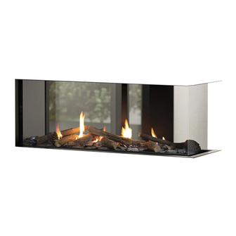
A1 Product Description The DN1150 Corner 400 gas fire is a room sealed gas appliance designed to be built into a false self supporting cavity. It is a powerful gas heater that, on the lowest setting (effect only) will still generate approximately 50% heat. - Page 7 UNDESIRABLE LEVELS OF HEAT, OR LEVELS OF HEAT GREATER THAN THEIR TOLERANCES ALLOW. SPECIFIERS AND INSTALLERS MUST CHOOSE MATERIALS WHEN IN THESE SCENARIOS THAT MEET THE CoMBustIBILItY ReQuIReMeNts AND tHe MAXIMuM seRVICe teMPeRAtuRes ALLoWeD BY tHe CHoseN PRODUCT. ESCEA TAKES NO RESPONSIBILITY FOR MATERIAL CHOICE AND REFERENCE SHOULD ALWAYS Be MADe to tHe ReLeVANt MAteRIAL MANuFACtuReR’s MAXIMuM seRVICe teMPeRAtuRes FoR tHe SUITABILITY OF USE.
-
Page 8: B Creating The Cavity
ͳ Electrical isolation switch ͳ Home automation network connections - ethernet cable layout THIS DN1150 CORNER 400 FIRE IS TO BE INSTALLED PRIOR TO ANY WALL LINING. THE WALL LINING IS THE VERY LAST TASK TO BE COMPLETED IN THIS INSTALLATION. -
Page 9: B3 Hearth
Escea in no way guarantees or takes responsibility that the recommended installation suggestion will be suitable for all electrical or home entertainment appliances. -
Page 10: C Installing The Flue
C1 Flue Configuration (If less than 8m flue length is required) If your flue system is less than 8m long (as shown in diagrams below), then a simple aluminium flexible flue is required. If you wish to install a longer flue run, then contact the Escea Advisory Team. Horizontally terminated: utilises the escea horizontal power flue enclosure kit. -
Page 11: C2 Flue Configuration (If More Than 8M Flue Length Is Required)
1.2m F-F Liner ial Flue 8m MAX 8m MAX 8m MAX External Internal C2 Flue Configuration (If more than 8m flue length is required) If your flue system is greater than 8m long (up to 40m long), then please contact the Escea Advisory Team at aa@escea.com for further guidelines. -
Page 12: C3 Installing The Horizontal Powerflue Wall Terminal Option
C3 Installing the Horizontal Powerflue Wall terminal option The horizontal powerflue wall terminal must be installed in the correct orientation (the small horizontal slot should be at the bottom). This allows for the correct operation of the flue system and prevents the ingress of water. The horizontal powerflue wall terminal must be weather- tight when installation is complete to prevent damage to the dwelling. - Page 13 Creating the Hole in the outside Wall When cutting the hole in the outside wall, be mindful of how the installation of the horizontal powerflue wall terminal will be finished; the installation must be weatherproof. Ideal Hole/Cavity size for Horizontal Powerflue Without Side Brackets With Side Brackets 298mm 360mm 298mm 298mm 175mm Excluding allowance for flue which exits here The horizontal powerflue wall terminal can be attached to the wall in two ways: A) From the front of the terminal:...
- Page 14 The following diagrams are excerpts from the Escea architect drawings and are available in full on our sill cover to cladding to comply website. These diagrams are recommendations, and your installation must comply with any local or...
-
Page 15: C4 Installing The Internal Vertical Powerflue (Uvp)
C4 Installing the Internal Vertical Powerflue (uVP) Note: For information regarding an external install of the UVP, go to section “Installing the External Vertical Powerflue (UVP)” on page 17. The Universal Vertical Powerflue (UVP) internal configuration is designed to have the fan, mounted within the roof space of the house, and the vertical Ø225mm diameter liner, containing a Ø100mm flexi, penetrate through the roof. - Page 16 The UVP-Internal kit is intended for use within an accessible roof space or ‘chimney’ construction. service access must be provided. Ensure installation complies with relevant building codes and regulations Typical Installation UVP Cowl 1.2m F-F Liner ‘Decktite’ or similar ashing Roof Space Ensure Power Flue unit is securely braced using integral brackets.
-
Page 17: C5 Installing The External Vertical Powerflue (Uvp)
C5 Installing the external Vertical Powerflue (uVP) Note: For information regarding an internal install of the UVP, go to section “Installing the Internal Vertical Powerflue (UVP)” on page 15. The UVP is designed to have the enclosure containing the fan unit mounted externally; an example is shown below. -
Page 18: C6 Installing In Accordance With Relevant Codes
C6 Installing in Accordance with Relevant Codes The location of the horizontal powerflue wall terminal must be installed in accordance with AS/NZS 5601 and any other relevant building codes. If possible, avoid installing the horizontal powerflue wall terminal in areas exposed to high winds and extreme weather. Some of the minimum clearances for a fan assisted wall terminal are listed below;... -
Page 19: C7 Running The Flue
Notes: Should the flue not extend past the apex, the bottom opening of the flue should extend at least 200mm from the roof (or 300mm in regions with heavy snow). The installation of a flue into a carport is not recommended. The flue terminal will get very hot when in use. -
Page 20: C8 Running The Powerflue Electrical Cable
C8 Running the Powerflue electrical Cable Note: The powerflue terminal is powered from the appliance and must be connected to the appliance with the supplied electrical cable only. Note: Ensure that the appliance power supply is disconnected before making the connection to the terminal The supplied electrical cable is 7m long;... -
Page 21: D Installing The Electricity And Gas To The Appliance
IN S TALLING T HE ELEC T RIC IT Y AND GA S TO T HE APPLIANC E D1 Power supply While the cavity is being created, consideration must be given to the location of an appropriate power supply. An earthed 230/240 volt mains power connection (typically a standard 3 pin outlet) must be available within 1m of the bottom right of the appliance. -
Page 22: D3 Gas Pipe Sizing
365 min* 1320 min* D3 Gas Pipe Sizing Gas pipe should be sized as per the requirements of AS/NZS 5601.1. The pipe sizing must be sufficient to deliver the following volume of gas to the heater with all other gas appliances in the home running at the same time: 850 min* Maximum DN1150 Corner 400 Gas Consumption = 33MJ/hr... -
Page 23: D5 Gas Isolating Valve
D5 Gas Isolating Valve A gas isolating valve must be installed in the gas line as close to the appliance as possible. Fix it in a convenient position to allow it to be closed off quickly and easily during normal operation. Take into consideration access to this valve once the wall linings are on. -
Page 24: E Installing The Appliance
IN S TALLING T HE APPLIANC E E1 Connecting the Flue Access the top of the appliance and connect both the inlet flue (Ø75mm ID/85mm OD) and the exhaust flue (Ø100mm ID/110mm OD) to their respective spigots. Tighten the hose clamps onto the spigots. Ensure the flue connection is air tight. -
Page 25: E4 Remove The Infill & Burners
THIS APPLIANCE IS CONFIGURED TO OPERATE ON NATURAL GAS, ULPG OR PROPANE. IF GAS TYPE CoNVeRsIoN Is Not ReQuIReD tHeN sKIP to tHe NeXt seCtIoN. If gas type conversion is required, please contact an Escea dealer to request the required parts. Follow the steps on the following pages to change from NG to ULPG/Propane or vice versa. - Page 26 Step 3: Replace the pilot jet (see tables) Note: Ensure the pilot jet is joined up to the olive before inserting the jet into the pilot assembly (as shown below). Step 4: Screw out the nylon adjuster screw inside the regulator to remove the existing spring. Replace the spring with the purple spring supplied in the conversion kit and reassemble the regulator.
-
Page 27: E6 Operating The Appliance
Note: The regulator that is supplied with the fire MUST NOT BE REMOVED. Removal of the regulator, or replacing it with one not intended for use with an Escea fire, will void the limited appliance warranty and may be dangerous. - Page 28 The gas valve (shown previous page) has manometer test points at A, C, and D. Ignore B. GAs PRessuRe tABLe - DN1150 CoRNeR 400 GAS TYPE ULPG Propane Minimum Inlet Pressure - Pre-Regulator 1.13 kPa 2.75 kPa 2.75 kPa Maximum Inlet Pressure - Pre-Regulator 5.0 kPa 5.0 kPa 5.0 kPa Operating pressure - Post-Regulator (Point C)
- Page 29 Whilst in test mode: press and hold the “Activate Timer” and “Fan Boost” buttons for 4 seconds to access the gas valve settings. The appliance will automatically turn on while in this mode. WAIT. Allow the appliance to fully light all burners before continuing.
-
Page 30: E8 Remote Pairing Button
E9 Home Automation setup Escea K-Series fireplaces have a simple interface for connection to a home automation system. This allows the fireplace to be woken up, started, and then shut down. The “Close to Wake” connection (shown below) is essentially taking one of the 3.3 volt DC pins on the fireplace micro-controller and... - Page 31 From Automation system Connector and terminal block supplied by Escea The home automation connection can be found in your fireplace accessory pack (shown right). This connects to the fireplace via the lower RH outside panel of the fireplace, next to the primary network cable access point, as shown in section “Network Cable”...
-
Page 32: F Finishing The Installation
FINI SHING T HE IN S TALL AT ION F1 Gem/Crystalight or Coal Fuelbed Installation If using the crystalight/gem or coal fuel beds, first place all the crystalight/gem or coal pieces in a single layer atop the burners and fuelbed tray. Cover the entire area except for the pilot shield, ensuring coverage right up to the edges of the firebox or glass. -
Page 33: F3 Log Fuelbed Installation
Malfunctions due to improper fuel media placement will not be covered under warranty. Log Index DN1150 Peninsula/Crn 400 Use the index above as a guide for selecting the correct logs. Log Setup DN1150 Corner 400 Step 1: Step 2:... -
Page 34: F4 Woodland Fuelbed Installation
Step 3: F4 Woodland Fuelbed Installation Logs must be located correctly as stated/depicted in this section. The final layout should replicate the picture shown in Step 3. Place the flakes in a single even layer after the logs have been located correctly (excess flakes should NOT be added if one even layer has been achieved). -
Page 35: F5 Flame Picture
Woodland Log Setup DN1150 Corner 400 Step 1: Step 2: Step 3: F5 Flame Picture An abnormal flame pattern will look long and stringy; it may cause soot to build up inside the firebox. -
Page 36: F6 Wall Linings
1288 Check that these are correct before proceeding. If an abnormal flame pattern is still present, please 1056 contact Escea. It is the responsibility of the installer to ensure a correct flame pattern. F6 Wall Linings The final wall lining can only be commenced after all previous applicable sections have been completed. - Page 37 The wall lining can be fixed to the gib fixing bracket (circled below). There are eight areas on the bracket (five circled below and three more on the opposite side) that can be used for fixing screws. Frameless The DN1150 LH-RH Corner is a frameless fire. It is necessary to ensure that the edge of the wall lining is finished in a tidy manner (for a nice plasterboard finish we recommend plasterboard Rondo stopping bead).
-
Page 38: F7 Locating Wall Mount Cradle For Wireless Control
⃝ A suitable distance away from the heater ⃝ Ideally 1.2m to 1.5m from the floor The radio frequency signal will go through some walls but for best results Escea suggest that the cradle position is less than 10 metres away from the heater. The best height to locate the cradle off the ground is about chest height. This gives a good average room temperature and easy access for the user. -
Page 39: F9 Normal Operating Sounds And Smells
These are all normal operating sounds and should not be considered as defects in your appliance. Fan: Escea gas appliances use electric fans to push heated air into the room. It is not unusual for the fan to make a “whirring” sound when ON. This sound will increase or decrease in volume depending on the speed setting of your fan. -
Page 40: G Installation Checklist
IN S TALL AT ION C HEC KLI S T GO THROUGH THE FOLLOWING CHECKLIST TO ENSURE YOU HAVE INSTALLED THE APPLIANCE CORRECTLY. ⃝ Correctly sized cavity to suit your fireplace and flue configuration ⃝ Correct clearances to combustibles ⃝ An electrical isolating switch to the appliance, accessible after finished installation ⃝ Correctly sized gas supply with a pressure test point, ensuring adequate supply with all other gas appliances in the dwelling running ⃝ Gas type conversion process carried out if required ⃝ A weather-tight installed horizontal or vertical powerflue terminal with clearance as specified by As/ NZS 5601.1. ⃝ If chosen, reasonable access to the outside face of the horizontal powerflue wall terminal for maintenance purposes and flue attached to the rear of the horizontal powerflue wall terminal leading back to the appliance (and similar for vertical powerflue terminals) ⃝... -
Page 41: H Service Manual
GAS AND ELECTRICITY SUPPLY MUST BE ISOLATED BEFORE ANY SERVICE OPERATION IS CARRIED OUT ON THIS APPLIANCE. THIS MANUAL SHOULD BE LEFT WITH THE APPLIANCE. ONLY USE ESCEA APPROVED SPARE PARTS. ESCEA SPARE PARTS ARE AVAILABLE FROM AN ESCEA DISTRIBUTOR OR RETAILER DO NOT MODIFY THIS APPLIANCE. H1 Annual Service Procedure ⃝ Isolate power and gas supply to fire. -
Page 42: H2 Error Codes
Note: An error code may not signify a fault/warranty issue; depending on the error code, it may signify that the remote batteries are dead or the LPG cylinder is empty. Refer to the section below and contact Escea if needed. Error Code suggested action The electronics have gone over temperature. -
Page 43: H3 Cleaning The Fuel Bed And Glass
The valve solenoids have failed the pre-ignition test. A wire may have dislodged or the valve solenoid is faulty. ͳ Check that the connections to each solenoid are secure and in place. The Valve Solenoid connections on the ends of the wires may need to be tightened (e.g. with a pair of Check Failure pliers) to ensure a robust connection to the valve terminal. -
Page 44: H5 Replacing A Remote Control
H5 Replacing a Remote Control If the wireless control becomes lost or damaged, a new one can be ordered from any Escea retail agent. When you have the new remote, the following procedure needs to be followed to “teach” the remote to only communicate with that fire. -
Page 45: H8 Removing Or Cleaning Fan
H8 Removing or Cleaning Fan As part of regular service procedure, it is recommended that the fan is removed for cleaning. Dust will build up on the fan rotor and in the cavity where the fan is located. This can be removed by the service person using a hearth brush and a vacuum cleaner. -
Page 46: H10 Pressure Switch Removal
H10 Pressure switch Removal Follow the steps in section E3 on page 24 to remove the glass. Follow the steps in section E4 on page 25 to remove the burners and infill. Carefully remove the mirror panel (grey below), by using the tab at the top to push it in an up motion before tilting it out of the product. Remove the 10 screws (shown in the diagram below) in the access hatch and carefully remove from the firebox. -
Page 47: H11 Replacing The Thermal Cut Out (Tco)
When reconnecting the pressure switch, be sure to connect the tubes as shown in the diagram below. The black tube should be connected between the grey side of the pressure switch and the low pressure port. The translucent tube should be connected between the black side of the pressure switch and the high pressure port. Black tube attaches to the white side - this connects to the low pressure port at the... - Page 48 Fan tCo (60°C) Access to this TCO can be made by following the steps in section “H9 Removing the Control Tray” on page 45 and removing the left hand fan (not exhaust side). Once the fan is removed you will see the TCO (circled in the diagram below).
-
Page 49: H12 Servicing The Horizontal/Universal Vertical Powerflue
H12 servicing the Horizontal/universal Vertical Powerflue Ensure the power to the powerflue is off by disconnecting the power to the appliance inside. If the appliance has been running, allow the powerflue to cool before attempting to service it. servicing a Horizontal Powerflue: Undo the screws on the outside of the powerflue box and separate the two parts, giving you access to the fan inside. -
Page 50: H13 Wiring Diagram
H13 Wiring Diagram 630719 DN1150 LH-RH CoRNeR 400 INstALLAtIoN MANuAL...
Need help?
Do you have a question about the DN1150 Corner 400 and is the answer not in the manual?
Questions and answers