Table of Contents
Advertisement
Quick Links
DFS Series
GAS FIREPLACE
Installation &
Service Instructions
IMPORTANT: THESE DF700 AND DF960 FIRES REQUIRE THE USE OF A 43MM
RESTRICTOR ON THE UVP POWERFLUE INTAKE PIPE (REFER TO SECTION C4 AND
C5).
IMPORTANT: THE FASCIA AND SECONDARY GLASS ARE CRITICAL COMPONENTS
OF THE FIRE AND MUST BE PROPERLY FASTENED PRIOR TO RUNNING THE FIRE
(REFER TO SECTIONS D2 AND F1).
IMPORTANT: KEEP THIS MANUAL AND ANY OTHER INSTRUCTION SHEETS THAT
COME WITH YOUR FUELBED AS THEY CONTAIN NECESSARY INFORMATION FOR
FUTURE SERVICING
630772_0
Advertisement
Table of Contents

Subscribe to Our Youtube Channel
Related Manuals for Escea DFS Series


Summary of Contents for Escea DFS Series
- Page 1 DFS Series GAS FIREPLACE Installation & Service Instructions IMPORTANT: THESE DF700 AND DF960 FIRES REQUIRE THE USE OF A 43MM RESTRICTOR ON THE UVP POWERFLUE INTAKE PIPE (REFER TO SECTION C4 AND C5). IMPORTANT: THE FASCIA AND SECONDARY GLASS ARE CRITICAL COMPONENTS OF THE FIRE AND MUST BE PROPERLY FASTENED PRIOR TO RUNNING THE FIRE (REFER TO SECTIONS D2 AND F1).
- Page 2 The heater must be installed according to these instructions and in compliance with all relevant building, gas fitting, electrical and other statutory regulations (e.g.. AS/NZS 5601). Any shortcomings in the appliance and flue installation will be the responsibility of the installer, and Escea will not be accountable for any such failings or their consequences.
-
Page 3: Table Of Contents
CONTENTS A Product Description and Installation Process Product Description Recommended Install Process B Positioning the Unit Removing the Fascia Removing panels to ease installation Unit Dimensions Corner Installations Hearth Rear & Side Wall Clearances C Installing the Flue Flue Configuration (if less than 4m is required) Flue Configuration (if more than 4m is required) Installing the Horizontal Power Flue Installing the External Vertical Power Flue (UVP) Installing the Internal Vertical Power Flue Installing in Accordance with Relevant Codes Running the Flue Running the Power Flue Electrical Cable Setting up the Flue Spigot Plate D Installing the Electricity and Gas to the Appliance Power Supply Removing the Glass Removing the Burners... -
Page 4: A Product Description And Installation Process
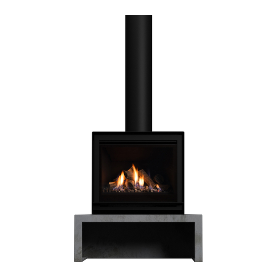
PRODUC T DES C RIP T ION AND IN S TALL AT ION PROC ES S A1 Product Description The Escea DFS console is a free standing unit designed to house the DF700 or DF960 gas fireplaces without the need for a cavity or masonry surround. -
Page 5: B Positioning The Unit
IMPORTANT: INSTALLATIONS THAT ARE NOT SPECIFICALLY OUTLINED IN THIS MANUAL SHOULD BE REFERRED TO THE ESCEA ARCHITECTURAL ADVISORY TEAM. PLEASE EMAIL AA@ESCEA.COM I.E. DF FLUE INSTALLATIONS OVER 4 METRES. To ensure that your installation is fully complete, please use the "Installation Checklist" on page... -
Page 6: B3 Unit Dimensions
B3 Unit Dimensions DFS730 124mm 511mm 756mm 378mm 378mm 755mm 497mm 736mm DFS740... -
Page 7: Top View
DFS940 GRC Plinth (DFS740 and 940 Only) 1016mm TOP VIEW 894mm FRONT VIEW... -
Page 8: B4 Corner Installations
B4 Corner Installations If a unit is to be installed in a corner, the following drawings give the minimum distance from interior walls. DFS730 317mm 50mm 50mm 50mm DFS940 DFS740 430 mm 522mm 50 mm 50 mm 50 mm 50 mm B5 Hearth A finished floor level hearth is not required, however it may be used for decorative purposes or for protection of flooring. -
Page 9: B6 Rear & Side Wall Clearances
B6 Rear & Side Wall Clearances The diagram (shown below) shows the recommended minimum clearances for the location of any DFS Series Unit in relation to a side wall. NOTE: The distance increases when the side wall extends forward of the fireplace. -
Page 10: C Installing The Flue
IN S TALLING T HE FLUE C1 Flue Configuration (if less than 4m is required) For vertical installs the black flue liner will accomodate the flexiflue pipes for the initial section of the run untill the penetration of the ceiling, once in the roof space the fluing can go horizontally or continue vertically as long as the run does not exceed 4m. -
Page 11: C2 Flue Configuration (If More Than 4M Is Required)
C3 Installing the Horizontal Power Flue Note: The appliance is designed only to operate using the approved flexible or PolyPro flue supplied by Escea. Other brands of flue may not fit, and this will affect the appliance warranty. The Horizontal Power Flue Wall Terminal must be installed in the correct orientation (the small horizontal slot should be at the bottom). - Page 12 Creating the Hole in the Outside Wall When cutting the hole in the outside wall, be mindful of how the installation of the Horizontal Power Flue Wall Terminal will be finished; the installation must be weatherproof. Ideal hole/cavity size for horizontal Power Flue Without Side Brackets With Side Brackets 298mm...
- Page 13 The following diagrams are excerpts from the Escea architect drawings and are available in full on our website. flashing tape over wall wrap to opening These diagrams are recommendations, and your installation must comply with any local or national building sill cover to cladding to comply codes.
-
Page 14: C4 Installing The External Vertical Power Flue (Uvp)
C4 Installing the External Vertical Power Flue (UVP) The UVP is designed to have the enclosure containing the fan unit mounted externally. Escea recommends this install for a UVP powerflue; an example is shown below. Note: When installing the unit onto a flue liner, ensure the length of flue liner above the roof is the minimum required length. -
Page 15: C5 Installing The Internal Vertical Power Flue
C5 Installing the Internal Vertical Power Flue Note: Internal install is only recommended for situations where an external install is unpractical. For information regarding an external install of the UVP, go to section C4 on page 14. The Universal Vertical Power Flue (UVP) internal configuration is designed to have the fan, mounted within the roof space of the house, and the vertical Ø225mm diameter liner, containing a Ø100mm flexi, penetrate through the roof. - Page 16 229.1 TIMBER MUST NOT OBSTRUCT THESE ZONES 31.6 31.6 221.8 250.2 ø226.8 103.4 The UVP-Internal kit is intended for use within an accessible roof space. SERVICE ACCESS MUST BE PROVIDED. Ensure installation complies with relevant building codes and regulations. UVP Cowl 1.2m F-F Liner ‘Decktite’...
-
Page 17: C6 Installing In Accordance With Relevant Codes
C6 Installing in Accordance with Relevant Codes The location of the Horizontal Power Flue Wall Terminal must be installed in accordance with AS/NZS 5601 and any other relevant building codes. If possible, avoid installing the Horizontal Power Flue Wall Terminal in areas exposed to high winds and extreme weather. -
Page 18: C7 Running The Flue
Notes: ͳ Should the flue not extend past the apex of the roof, the bottom opening of the flue should extend at least 200mm from the roof (or 300mm in regions with heavy snow). ͳ The installation of a flue into a carport is not recommended. ͳ... -
Page 19: C9 Setting Up The Flue Spigot Plate
IF YOU DO NOT CONNECT THE POWER FLUE ELECTRICAL CABLE TO BOTH THE FIREPLACE AND THE POWERFLUE, THIS WILL RESULT IN AN ERROR WHEN THE FIREPLACE IS TURNED ON. TEST THE FAN BEFORE CONTINUING WITH THE REST OF THE INSTALLATION. Tie the Power Flue cable onto the Ø75mm Air Flexi Flue as shown below. -
Page 20: D Installing The Electricity And Gas To The Appliance
IN S TALLING T HE ELEC T RIC IT Y AND GA S TO T HE APPLIANC E In order to install gas to the fireplace, check the operating pressure or install the network cable, the glass and burner tray needs to be removed. D1 Power Supply While the unit is being situated, consideration must be given to the location of an appropriate power supply. -
Page 21: D3 Removing The Burners
Primary Glass Remove the two screws holding in the top of the primary glass, then pull forward, tilt down and then slide out the glass retainer through the gap in the side flanges. NOTE: Please slide the top trim ramp forward with caution to avoid scratches to the finish as the front of the part is visible. -
Page 22: D4 Gas Pipe Sizing
FRONT Fire mounting holes D6 Gas Supply Escea does not condone using a 9kg bottle as the main gas supply for an Escea fire. Doing so could result in a dirty or poor flame and produce excess soot build up. -
Page 23: E Installing The Appliance
IN S TALLING T HE APPLIANC E E1 Securing the Unit Escea recommends securing the Freestanding units down to the floor using the four holes located in the bottom of the units. The DFS730 fixing holes are easily accessible from the inside of the unit. -
Page 24: E2 Routing The Powerflue And Power Cable
E2 Routing the PowerFlue and Power Cable Carefully push the fireplace into the unit just enough to bring the powerflue cable through the silicone grommet of the appliance shown in the diagram below. This will be plugged in later in the process. The power cable and home automation cabling can be run either ͳ... -
Page 25: E4 Move To The Main Manual
Make sure that all of the fold up tabs (circled in the diagram below) used for locating the flue spigot plate onto the chassis are poking through the flue spigot plate. Note DF960 has 6 tabs. Insert the 1 long machine screw into the location shown in the diagram above to secure the flue spigot plate to the chassis E4 Move to the Main Manual Move to the main DF700 &... -
Page 26: F Installation Checklist
IN S TALL AT ION C HEC KLI S T Go through the following checklist to ensure you have installed the appliance correctly ⃝ Correctly situated freestanding unit to suit your flue configuration ⃝ Correct clearances to combustibles around the freestanding console ⃝...
Need help?
Do you have a question about the DFS Series and is the answer not in the manual?
Questions and answers