
Related Manuals for Oilon GP-600 M


Summary of Contents for Oilon GP-600 M
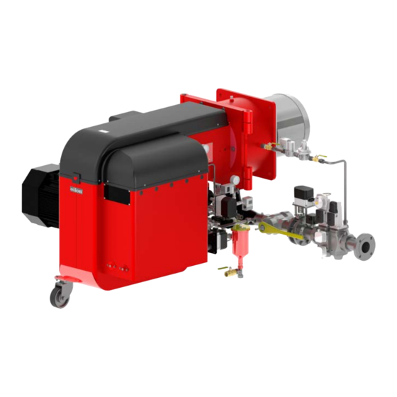
- Page 1 M4219 2305EN 6 April 2023 Operation and maintenance manual Burner models: GP-600 M - 700 M-III Burner equipment: WDx00, FGR (UL) Read these instructions carefully before installation, use, or maintenance...
-
Page 3: Table Of Contents
Contents Introduction Liability disclaimer..................3 Safety precautions..................3 Product overview..................7 Flue gas recirculation (optional)..............9 Handling and storing.................10 Technical data Burner technical data................11 Other technical data and requirements............ 12 Burner control technical data..............13 Servomotor technical data................ 15 Display and operating unit technical data..........15 module technical data (WD200)............15 Oxygen sensor technical data (WD200)...........16 Flame detector technical data.............. - Page 4 4.15 Setting ratio curve..................54 4.16 Activating FGR..................58 4.17 Setting FGR curve points................. 59 4.18 Measuring FGR..................60 4.19 Capacity range..................61 4.20 O2 min. value control (WD200)..............62 4.21 Setting O trim control (WD200)...............64 4.22 O2 trim control operating mode (WD200)..........65 4.23 trim control load limitation (WD200)............66 4.24...
-
Page 5: Introduction
Oilon is unable to accept any liability for damage in case of: ● failure to follow these instructions ● other use than what is explained in this manual ●... - Page 6 Keep these instructions as well as the electrical diagrams available near the device. Oilon products are manufactured in accordance with general product standards and directives as well as based on our best knowledge of product design and different technologies. Operational safety is one of the leading principles in our product development.
- Page 7 Cut off power supply to the burner and close the manual shut-off valves always before any maintenance work. Cutting power is adequate when just inspecting the device. Secure all safety covers, enclosures, and guards with all screws before start-up. Use appropriate tools. Wear proper hearing protection and personal protective equipment, such as protective footwear, gloves, and safety goggles when necessary.
- Page 8 Take care of the boiler room Never light a fire in the boiler room. Do not store any inflammable materials in boiler room. Keep the boiler hatch closed while starting the burner and during burner operation. ● Maintain tidiness in boiler room, and keep boiler room door closed. ●...
-
Page 9: Product Overview
The manufacturing time is found in the type plate. The product's expected lifespan is at least 15 years, if it and its components are used and maintained properly. For more information on products, visit our website at www.oilon.com. M4219 2305EN... - Page 10 Label element 7: Combustion head length (additional code) -, C1, C2, C3 Combustion head length C only in use in LN80 burners. Type plate The following illustration shows an example of the type plate of Oilon burners: 8 (111) M4219 2305EN...
-
Page 11: Flue Gas Recirculation (Optional)
Type plate US ver. 2 Pos. Description Pos. Description Burner type: Oil pump supply voltage, input power and KP = Light fuel oil current, V / Phase / Hz / hp / A RP = Heavy fuel oil Degree of protection GP = Gas Serial number GKP = Light fuel oil and gas... -
Page 12: Handling And Storing
1.5 Handling and storing Storing and recycling Store the device and its equipment in the manufacturer's packaging in a dry and airy place. Protect device from dust and humidity. Condensation, formation of ice and ingress of water are not permitted. If these requirements are not met, the device's safety functions may be compromised. -
Page 13: Technical Data
However, the manual is valid only for the burner, mentioned on the front page and in the burner data table. Following information applies to standard deliveries. Burner data Burner GP-600 M Capacity, MMBtu/h 3.7–25.6 Burner motor 3~ 208–600 V 60 Hz ●... -
Page 14: Other Technical Data And Requirements
Working diagrams Using the burner outside the range shown in the working diagrams is not allowed. GP-600 M - 700 M-III (UL) ver. 1 Tested in laboratory conditions (ambient temperature 68 °F). 2.2 Other technical data and requirements Fuel, gas use... -
Page 15: Burner Control Technical Data
Sound pressure level L 91.0 ± 0.5 dB Sound power level L 108.5 ± 0.5 dB For reducing noise level, contact the manufacturer or consult the Oilon Selection Tool (available for download on the Oilon website). Degree of protection NEMA 1 Ambient temperature range 32...+ 122 °F... - Page 16 Block diagram of contact links Block diagram ver. 7 14 (111) M4219 2305EN...
-
Page 17: Servomotor Technical Data
Inputs / outputs (VSD) Connection diagram ver. 3 2.4 Servomotor technical data Servomotor SQM45... SQM48.497 SQM48.697 SQM91.391A9 Mains voltage 2 x 12 VAC 2 x 12 VAC 2 x 12 VAC 2 x 12 VAC Power consumption 9 – 15 VA 26 –... -
Page 18: Oxygen Sensor Technical Data (Wd200)
module PLL52... Analog inlet, oxygen sensor QGO21.000D27 Analog inlet, combustion temperature Pt1000 / LG-Ni 1000 Analog inlet, flue gas temperature Pt1000 / LG-Ni 1000 Analog inlet, bus interface Protection degree NEMA 3 Permissible ambient temperature -4..+140 °F Protect the equipment from condensation, ice, and water ingress. 2.7 Oxygen sensor technical data (WD200) Oxygen sensor QGO20... - Page 19 Auxiliary detector cable max. length 328 ft Protection degree NEMA 3 Permissible operation ambient temperature -4...+140 °F ● integrated signal amplifier ● continuous or interrupted use ● mains frequency filtering ● does not detect electric arc used for ignition ● spectral sensitivity range ~1–3 μm ●...
-
Page 20: Installation
3 Installation 3.1 Lifting the burner ● The unit may be lifted only by qualified personnel with a good understanding of the regulations and safety instructions for lifting. ● Always use all indicated lifting points of the particular lifting direction. ●... -
Page 21: Installing Burner
Installation, commissioning, or service of the appliance is to be carried out by authorized and trained personnel only, adhering to all local regulations and requirements. Minimum Legend dimension, ft (left) (front) (right) (top) Space requirements ver. 1 It is recommended to leave more space around the burner. These are only the minimum requirements. - Page 22 Burner dimensions (GP) Burners with external cabin Dimensions in inches Burner 600 M 64.96 12.20 11.61 5.71 42.91 41.73 30.71 16.54 14.37 700 M 64.96 12.20 11.61 5.71 47.24 41.73 30.71 16.54 13.19 700 M-II 64.96 12.20 11.61 5.71 47.24 41.73 30.71 16.54...
-
Page 23: Combustion Head And Masonry Dimensions
3.4 Combustion head and masonry dimensions Combustion head mounting dimensions d071827 ver. 1 Masonry 1 ver. 3 Pos. Item Pos. Item Gasket, thickness 0.3 inch Ceramic wool or equivalent Mounting panel Masonry Burner øD4 øD1 α 600 M 18.31 18.31 17.91 4xM20 15.55... - Page 24 d078617 ver. 2 Pos. Item Pos. Item Stud screw, 4 pcs Burner flange with combustion head Flange gasket (boiler side) Washer, 4 pcs Extension plate Hex nut, 4 pcs Flange gasket (burner side) To install the extension plate: 1. Attach the supplied stud screws securely to the boiler. 2.
-
Page 25: Burner Hinges
3.5 Burner hinges Swinging the burner open ver. 4 As standard, the burner swings to the left. Right side hinging is delivered on request only. Switch off electric power from the burner before swinging the burner open. 3.6 Installing burner to gas supply line Supply line If necessary, decrease the supply gas pressure with pressure regulating assembly. - Page 26 If the gas inlet pressure is not stable, stabilize with pressure regulator. Install gas lines in accordance with regulations by local public authorities. Check that there is a separate filter upstream from gas equipment. Install the gas valve so that the valve is not subjected to mechanical stress.
-
Page 27: Gas Valve Selection Table
B-349T ver. 1 Place the supports under the gas pipe (1) and gas valves (2) as depicted in the illustration. 3.7 Gas valve selection table Gas valves Gas valve Min. inlet gas Max. inlet gas Burner pressure PSI" pressure PSI" Type Size inch 600 - 700 M-III... - Page 28 ● gas supply pressure ● secondary pressure ● the volume of gas to be fired ● type of gas If the gas inlet pressure is higher than the Pmax. value given in burner’s technical data or PI diagram, reduce the gas inlet pressure in the regulating assembly. If the pressure regulator is not equipped with a safety relief valve and safety shut-off valve, install these valves according to the instructions given by the manufacturer.
-
Page 29: Installing Fgr Duct System
3.9 Installing FGR duct system FGR duct system FGR Installation_monoblock ver. 3 Pos. Item Pos. Item Control damper Temperature sensor Combustion air fan FGR duct Combustion air throttle valve Condensate drain valve Combustion air In monoblock burner constructions, pos. 2 and 3 are integrated parts of the burner. Burner Minimum diameter of FGR pipe... - Page 30 In long pipe runs the pipe line length can change by over 1" per 212° F. Thus extra load builds up on pipe connection point, which may result in component failures. Apply the following rules of thumb for the construction: ●...
-
Page 31: Changing The Fuel Type From Natural Gas To Lpg
Temperature sensor Butterfly valve FGR pipe (*) Burner Sleeve (*) Min. 7.87 in * not included in delivery 3.10 Changing the fuel type from natural gas to LPG This information applies only when liquefied petroleum gas (LPG) is used. Adjusting band Gas nozzle Fixing screw of adjusting band... - Page 32 Configure the burner installation with a switch that allows it to be disconnected from the supply mains. Grounding must be in order before commissioning burner. See the electrical diagram for maximum cable lengths. Burners with an integrated control system have separate power supply connections for both the burner’s motor and its control circuit.
-
Page 33: Commissioning
4 Commissioning 4.1 First start-up Secure all safety covers, enclosures, and guards with all screws before start-up. Use appropriate tools. If burner start-up fails consecutively three times, do not restart burner before carefully investigating the reason for the failure. After the first start-up check the cleanliness of the gas filter weekly and replace if necessary. -
Page 34: Adjusting Combustion Air
● gas inlet pressure is correct ● equipment is installed correctly and is in working condition ● chimney is properly connected, unobstructed and flue gas damper is open To start the burner: 1. Open the manual fuel shut-off valves. 2. Switch on power supply. 3. - Page 35 Combustion air US ver. 1 Guideline values Capacity Fuel O2 level % Ignition, minimum and part capacity 3.5–4.5 Full capacity 2–4 If you alter the position of the adjustment ring in relation to the diffuser disc, the quantity and velocity of combustion air in the combustion head will change.
-
Page 36: Adjusting Combustion Head
4.3 Adjusting combustion head Combustion head components D074560_1 ver. 1 Pos. Description Pos. Description Mounting flange Oil nozzle valve (GKP, GRP, KP, RP) Combustion head Oil nozzle (GKP, GRP, KP, RP) Adjusting ring Ignition electrode Diffuser disc Ignition electrodes fixing screw Gas nozzle (GP, GKP, GRP) 34 (111) M4219 2305EN... - Page 37 Set the following as shown in the illustration: ● gas nozzle horizontal distance from the back of the diffuser disc (A) ● diffuser disc front horizontal distance from the combustion head (C) Dimensions in inches. Burner model GP-600 M, GP-700 M 0.91 – 5.79 GP-700 M-II 0.91...
-
Page 38: Adjusting Combustion Differential Air Pressure Switch
300 - 700 0.47 0.35 0.12 0.55 0.91 A496V ver. 5 4.4 Adjusting combustion differential air pressure switch Combustion differential air pressure switch The combustion differential air pressure switch monitors the pressure difference generated by the burner fan. Pos. Item Higher pressure Lower pressure Electrical connections... -
Page 39: Adjusting Gas Pressure Switch
Burner Factory setting "W.C. 300 M-II 12.5 400 M-I – 600 M 16.1 700 M - 700 M-III 20.1 When using variable speed drive ● factory setting is set to 4.01 "W.C. ● maximum adjustment range should be between 35 Hz and 50 Hz To ensure proper burner function, the differential air pressure switch may have to be readjusted to match the actual conditions at the installation site. - Page 40 Burner Factory setting "W.C. 300 M-II 12.5 400 M-I - 600 M 14.9 700 M - 700 M-III 20.1 To adjust gas pressure switch to maximum, without flue gas analyzer Adjust gas pressure switch after burner adjustments and flue gas analysis. 1.
-
Page 41: Setting Gas Pressure Regulator Skp
The operating area of the gas pressure regulator is determined by the spring installed inside the pressure regulator. Spring operating area is described in the table below. Springs can be ordered from Oilon Webshop. SKP ver. 1 To change spring: 1. -
Page 42: Setting Gas Pressure Regulator Frs
The factory setting of standard spring p is 4 - 12 in.WC. Springs can be ordered from Oilon Webshop. Setting pressure regulator at minimum load 1. Start burner at minimum load. At minimum load throttle valve setting is 5°-10°. - Page 43 To adjust outlet pressure 219598a ver. 1 1. Unscrew protective cap A. 2. Use a chisel-point screwdriver. to adjust spindle B: a. Turn the spindle B clockwise. This increases the outlet pressure. b. Turn the spindle B counterclockwise. This reduces the outlet pressure. 3.
-
Page 44: Measuring Gas Pressure
FRS4 ver. 2 Protecting cap sealing hole, ø 0.06 in Body sealing hole, ø 0.06 in Setpoint Color Nominal width Rp/DN spring range ("W.C) Rp 1 1/2, Rp 2, DN Rp 2 1/2, DN 100 DN 125 DN 150 DN40 DN65, 80 Spring 1 1.0–3.6... - Page 45 All stated pressure values are only for reference. The actual values may vary depending on operating conditions. Measuring nozzle pressure D048641 ver. 2 1. Nozzle pressure at nominal capacity Burner Test point 1 ("W.C.) 300 M-II 400 M-I 500 M 12.5 600 M 15.3...
- Page 46 Measuring inlet and adjusted pressure Main gas train + pilot gas train d073474_2 ver. 1 d073474_1 ver. 3 A. Gas inlet 4. Measuring point 2. Inlet pressure 5. Inlet pressure (pilot) 3. Adjusted pressure 6. Adjusted pressure (pilot) Burner Test point 2 Test point 3 ("W.C.) ("W.C.)
-
Page 47: Operating And Display Unit Menu
4.9 Operating and display unit menu Menu structure Menus are divided into two user levels. First user level is User, and it does not require password. Second user level is Service. It is a password protected level for commissioning and maintenance personnel. - Page 48 StartCounter Displaying the start counter readings GasStartCount Number of startups gas, start counter (selectable) OilStartCount Number of startups oil, start counter (selectable) TotalStartCountR Total number of startups, start counter (can be reset) TotalStartCount Total number of startups, start counter (read only) Fuel Meter Displaying the current counter readings...
- Page 49 Description ManualOperation SetLoad Target load setting manually, percent of maximum load (%) Autom/Manual/Off Select manual or automatic operation Auto Burner capacity adjusts automatically controlled by capacity controller according to boiler temperature or pressure Burner on Burner on manual operation according to SetLoad Burner off Burner stopped...
-
Page 50: Adjusting Operating And Display Unit Settings
VSD Module ● Configuration ● Process Data ● ProductID ● SW Version 4.10 Adjusting operating and display unit settings Scrolling menus For scrolling and changing set values of the operating and display unit menu, use the four buttons on the panel. AZL buttons ver. -
Page 51: Variable Speed Drive Settings And Standardization (Wd200)
4.11 Variable speed drive settings and standardization (WD200) In 700 M-III burners with a 60 Hz configuration, the maximum output frequency is 52.5 Hz. The variable speed drive is used for fan motor control. The burner controller starts and stops the variable speed drive with a potential-free release contact. The VSD sends alarm data to the burner controller using a 12–24 V DC alarm signal. -
Page 52: Checking O Module (Wd200)
Num Puls per R Three pulses per round. Do not change the setting manually! Standardization automatic test for fan maximum rotation speed. Burner control should be in standby position when the test begins. Select activated from the menu to start the test. 1. -
Page 53: Manual Start-Up And Program Stop In Pre-Purge Position
QGO SensorTemp QCO sensor temperature in °F QGO HeatingLoad Control value of QGO... heating, 0,1% QGO Resistance Internal resistance of QGO's Nernst cell Self test is made at 23-intervals. Test requires constant O level, for e.g. after pre-purge or on steady load. If constant O level is not reached within 24 hours, burner control locks down operation load to reach constant O level for next test. -
Page 54: Ignition Position
36 IgnitPos 44 Interv 1 52 Interv 2 72 PostPPos 76 PostPFGR Manual start-up Prerequisites: ● Frequency converter parameters are set and adjusted. ● Interlocking and failures are reset. ● Program phase is 12, Stand by. ● In heavy fuel oil use preheater temperature is sufficient. Activate manual burner start-up from menu level Autom/Manual/Off by choosing BurnerOn: ManualOperation... - Page 55 ● gas is selected as fuel, and it is the first start-up ● burner control has been unenergized ● it has been a long time from previous shutdown ● it is a start-up after safety shutdown or lockout reset During standard stop, valve leak test is carried out before pre-purge period. 1.
-
Page 56: Setting Ratio Curve
4.15 Setting ratio curve Curve points There can be 15 curve points at the maximum. Set curve points in the following menu level: Params. & Display RatioControl GasSettings CurveSettings Point Manual Creating curve point individually Current servomotor positions in degrees, variable speed drive control and capacity in percentages are shown on the right side of the display, starting from the top corner. - Page 57 If you want to set a new curve point, press Enter, when XXXX is displayed as the set value. The ignition position will automatically be set as the first ratio curve point, from which the burner minimum load point is adapted. Editing individual curve point To change an existing curve point: 1.
- Page 58 Press Enter at the desired parameter. Curve point 6 ver. 4 Change setting using the Select -/+ buttons. Then servomotors drive to their new position. During that time, the display shows “>” instead of “:”. Confirm the change by pressing Enter or undo by pressing Esc. Then you return to the previous menu level. The servomotor turning angle is 0–90°...
- Page 59 Curve point 9 ver. 5 3. Servomotors follow an imaginary linear curve towards the maximum or minimum load. The oxygen value can be monitored on the display. When increasing load, monitor that combustion values do not increase to a hazardous level. If necessary, set curve point for interval by pressing Enter, and correct servomotor positions to return combustion values to a normal level.
-
Page 60: Activating Fgr
Check combustion values with ignition load using flue gas analysis. When curve points have been set, exit from the curve setting menu level, and set the burner to operate at minimum load from manual operation menu level. Description ManualOperation SetLoad Fixed load setting on manual operation, percentages of maximum load (%) -
Page 61: Setting Fgr Curve Points
For further instructions, see the section Setting FGR curve points. 4.17 Setting FGR curve points The FGR curve points are set at the fuel-air ratio curve. During the time the curve menu is in use, the state of the FGR function does not change. This means that if the AUX3 is still at the ignition position when setting parameters, it maintains the position until the curve setting is completed. -
Page 62: Measuring Fgr
Changing curve settings may have an impact on the combustion settings. Check the servomotors regulating fuel and air. Readjust if needed. You can save changes to the operating and display unit memory. Answer yes to the screen message that appears when leaving Params. & Display menu level. For more detailed instructions on setting, monitoring, and editing curve points, see section Setting ratio curve. -
Page 63: Capacity Range
Natural gas combustion, flue gas recirculation (%) FGR natural gas ver. 2 Flue gas O2 = 2% Flue gas O2 = 3% Flue gas O2 = 4% Y axis: FGR, %, X axis: Mixture O2 content (dry), %. FGR may cause unstable combustion. To avoid noise, vibration or other disturbance, the settings must always be defined for each burner separately. -
Page 64: O2 Min. Value Control (Wd200)
LoadLimits MinLoadGas. Minimum load "Low fire" (gas) MaxLoadGas Maximum load "High fire" (gas) At the user level, maximum load can be set individually as follows: Description Operation User Maxload User MaxLoadMod Maximum load on modulating burner 4.20 O2 min. value control (WD200) O2 ratio control can be set after setting the ratio curve. - Page 65 Maximum permitted values: CO = 4000 ppm, #2 on the Shell-Bacharach scale. Values may vary depending on the type of the configuration. If you change the ratio curves at a later date, the minimum value must also be readjusted. O2 min. value direct entry 1.
-
Page 66: Setting O Trim Control (Wd200)
4.21 Setting O trim control (WD200) min. value O2Control must be set first. It is important that environmental conditions do not change when setting O trim control. If you change the curves at a later date, O trim control must also be adjusted. -
Page 67: O2 Trim Control Operating Mode (Wd200)
Point22 ver. 4 4. The display changes. The third line shows the current residual oxygen level. The pointer is on StandardVal. Reduce the air by pressing the Select -/+ buttons, if necessary. A larger number at this point means larger without air throttle. When desired oxygen level is reached, press Enter. -
Page 68: O 2 Trim Control Load Limitation (Wd200)
Params. & Display O2Contr/Guard FuelSettings OptgMode auto deact man deact O2 Limiter O2 Control conAutoDeac O2 trim control operating modes Use this setting when creating O2 ratio curve. man deact Both O2Limiter and O2Control are deactivated. Burner operates according to parameterized ratio curves. -
Page 69: O 2 Trim Control When Load Changes (Wd200)
Apadt.Point small Type of Fuel Fuel user def If load drops below this limit, the burner operates along parameterized ratio curves without O trim control. Set load limitation after setting O trim control ratio curve. Load limitation is usually curve point 2 load from basic parameterized ratio curve. 4.24 O trim control when load changes (WD200) When load changes under unfavourable setting conditions, the actual O... -
Page 70: Setting Load Controller Parameters
ManualOperation Autom/Manual/Off Autom Burner on Burner off 3. Burner control capacity controller keeps boiler temperature or pressure constant by changing burner capacity as necessary. The capacity controller shuts down and restarts the burner as necessary. Select the control parameters for the capacity control from the menu as follows: Params. - Page 71 very fast fast normal slow very slow Standard parameters are listed in the following table: Proportional band [%] Integral action time [s] Derivative action time [s] Very fast 42.5 Fast 14.5 Normal Slow Very slow Setting parameters individually PID parameters can also be set individually according to the following value range: ●...
- Page 72 Params. & Display LoadController Adaption StartAdaption AdaptionLoad The burner and boiler must be ready for 10 min. run, where boiler temperature or pressure is dropped to 5 % below set value, and then run with full load. This occurs automatically according to the following diagram. Boiler load should stay constant throughout adaptation.
- Page 73 Select StartAdaption. Parameter evaluation Load control does not cause variation in boiler temperature or pressure with optimum PID parameters. When changing the setting, boiler temperature or pressure should stabilize without going up and down. Pressure and temperature must not go under or exceed set values.
-
Page 74: Capacity Controller On/Off
Params. & Display LoadController ControllerParam MinActuatorStep SW_FilterTimeCon MinActuatorStep is the minimum possible actuator step. This affects the load controller accuracy but may stabilize its action. If the value for this parameter is too high, the load control becomes unstable. The factory setting is 1%. SW_FilterTimeCon. -
Page 75: Boiler Temperature Limiting With Burner Control
4.28 Boiler temperature limiting with burner control Boiler temperature can be limited with burner control. It can be implemented with the same sensor used for temperature control, or with a separate sensor. When pressure control is selected, temperature limiter is not in use. If limiter temperature switch-on point is reached, burner shuts down. -
Page 76: Measuring Flue Gas And Combustion Air Temperature (Wd200)
ThresholdOn 40% of set value StageLoad 15% load step StageSetp_Mod 10% of set value StageSetp_Stage MaxTmeMod 5 minutes MaxTmeStage ThresholdOff 80% of set value AdditionalSens Setp AddSensor Release Stages Cold start thermal protection operation example. Cold start ver. 4 4.30 Measuring flue gas and combustion air temperature (WD200) Flue gas and combustion air temperature measuring sensor can be connected to O module. -
Page 77: Activating O Trim Control (Wd200)
FlueGasTempSens MaxTempFlGasGas MaxTempFlGasOil 4.31 Activating O trim control (WD200) At the end of commissioning activate O trim control from the display and operation unit menu. Operation O2Ctrl activate deactivated activated 4.32 Backing up parameters 1. Start backing up parameters by selecting the following from the display and operating unit: Updating ParamBackup... -
Page 78: Operation
5 Operation 5.1 WiseDrive system WiseDrive 100 / 200 WiseDrive system components 1. Boiler pressure/ temperature measurement 2. Safety devices 3. O2 sensor (WD200) 4. O2 module (WD200) 5. CAN BUS 6. Control unit 7. CAN BUS 8. Gas damper 9. - Page 79 The system includes an operating and display unit for local use. A remote PC application can be used during commissioning and servicing. To enable continuous operation, the WiseDrive system uses components designed specifically for this system. The system supervises components related to safety functions with continuous self-testing.
- Page 80 Combustion air Combustion air provides the needed air pressure and volume for efficient combustion. In the WD200 system, the fan motor can be fitted with a variable speed drive. The variable speed drive adjusts air pressure according to burner’s capacity by controlling the fan speed.
-
Page 81: Control Panel
Oxygen sensor (WD200) Oxygen sensor measures the amount of residual oxygen from flue gas. The sensor is a ceramic zirconium dioxide cell and self-testing. QG020 ver. 3 Flame detector QRI is a flame detector for use with gas, oil and other flames that emit infrared light. Flame signal intensity can be monitored on display. -
Page 82: Legend To Time Sequence Diagrams
Control switch Switch State position 0 - STOP Burner start-up by control devices is prevented. If the switch is turned to the ‘0’ position while the burner is running, a controlled shutdown is initiated. The green indicator light on the switch indicates that the control voltage for burner automation (burner control, servomotors) is switched on. - Page 83 Pre-purge time part 1 tmn1 Min. time extraneous light test (5 s) after skipping pre-purge Pre-purge time part 3 tmx1 Max. damper running time Min. ON time oil pump tmx2 Max. time startup release Pre-ignition time gas/oil tmx3 Max. time circulation heavy oil Pre-ignition time OFF Post-purge time Interval 1 gas/oil...
- Page 84 Output OFF / input Irrelevant Output ON / input ON Permissible positioning range In Standby: actuator can move within the permissible positioning range, but is always driven to the home position. It has to be in the home position before changing the phase. 0°...
-
Page 85: Burner Operation And Pi Diagram, Gas
Heavy oil direct start Restricted startup behavior Restricted safety loop 5.4 Burner operation and PI diagram, gas Combustion air Fan (50 - 280) ver. 1 The burner is equipped with a fan which is designed to produce consistently high air pressure. This is required for flawless ignition and good combustion in modern combustion chambers. - Page 86 PI diagram Gas use, VGD valve, M series Pos. Item Pos. Item Manual shut-off valve Manual shut-off valve Pressure switch, low Air damper Safety shut-off valves Servomotor 3.1 Valve Combustion air fan 3.2 Actuator + 3.4 (optional) Electric motor 3.3 Actuator with pressure regulator + 3.4 Differential pressure switch for air 3.4 Proof of closure switch (IRI: 2 pcs, when capacity >...
-
Page 87: Time Sequence Diagram, Gas Use
5.5 Time sequence diagram, gas use 7550f57e/0515, Gp1 ver. 6 M4219 2305EN 85 (111) -
Page 88: Burner Automation Description, Gas Use
7550f60e/0515, Gp2 ver. 2 5.6 Burner automation description, gas use Items marked with an asterisk (*) apply only if the burner is equipped with an ignition gas valve. Prerequisites for start ● All failures and interlocks reset. ● Burner flange limit switch closed. ●... - Page 89 ● Remote control contacts closed. ● Boiler thermostat/pressure switch contact closed. ● Differential air pressure switch contact open. 20, 21 Start-up ● Burner control safety functions are activated. ● Gas safety valve (optional) opens. ● Gas pressure recognition, pressure switch min. closed. ●...
- Page 90 52* Interval 2, second safety time ends. ● Ignition gas valve closes.* ● The main flame must have been ignited by now. Otherwise, burner control does not receive a flame signal and goes to a lockout.* ● Main flame burns at a set ignition load.* 54 Servomotors run to min.
-
Page 91: Gas Valve Proving
00 Lockout phase ● Servomotors run to stand-by position. ● Burner failure activates. ● Requires manual reset. 5.7 Gas valve proving The system performs gas valve proving using a pressure switch or transmitter that monitors the section of pipe between the valves. During gas valve proving, burner control opens and closes gas valves at programmed intervals. -
Page 92: Maintenance
A blockage in the combustion head may cause a hazard. If you need help with maintenance issues, contact your nearest representative or visit the Oilon website (https://oilon.com) for technical support. The burner contains electric and electronic components. Adhere to rules and regulations from local authorities when disposing. - Page 93 To maintain flawless operation, do the following at least once a year: 1. Check burner head extension, and change if necessary. 2. Check diffuser disc, and change if necessary. Check burner adjustments if diffuser disc appears dirty. 3. Check ignition cable condition from the whole length. Change, if necessary. 4.
- Page 94 Adjustment lever Adjustment rod Body Combustion head A504J ver. 4 To open the burner: 1. Switch off power to the burner from the control switch. 2. Close the gas supply from the gas shut-off valve. 3. Detach the oil hose or hoses. Clean any oil dripping from the oil line with an oil- absorbent wipe or similar.
-
Page 95: Maintenance During Shutdown
Start operation only after a thorough inspection. Before start-up, make sure that the appliance is in good working order. If you need help with maintenance and service, contact your nearest representative or Oilon customer service. 6.3 Dismounting combustion head (GP, GKP) Check the O-ring during assembly. Replace if necessary. - Page 96 Combustion head components (GP) Gas nozzle Gas nozzle fixing screw Ignition gas nozzle Support pipe fixing screw Support pipe O-ring B-340R ver. 4 Appearance of parts may vary. 94 (111) M4219 2305EN...
-
Page 97: Dismounting And Changing Burner Motor
Disassembling nozzle valve (GP) Dismount ignition nozzle (if equipped). Loosen support pipe fixing screw. Loosen gas nozzle fixing screw. Lift support pipe a bit, and pull it out. Lift gas nozzle and pull it out. Note O-ring at the nozzle bottom flange. Dismounting combustion head from burner 1. - Page 98 Fan cross section Motor Fan wheel Fixing sleeve Wedge Fixing screw of fan wheel Base bushing Fixing screw of mounting flange A416L ver. 3 If necessary, lift the fan motor with a lifting device or strap. To dismount motor and fan wheel: 1.
-
Page 99: Assigning Servomotors
6.5 Assigning servomotors Addressing servomotor 1. Open servomotor protecting cover fixing screws, and remove cover. 2. Check that terminating resistor is connected as in the original servomotor. 3. Check the state of green signal light. If light is steady, servomotor is unaddressed and is ready for addressing. -
Page 100: Dismounting And Changing Servomotors
Param. & Display RatioControl Fuel settings Special settings Initial stage Initialstage Gas Initialstage Air Initialstage Aux1 Initialstage Aux2 Initialstage Aux3 In standby position run servomotor´s axle between 2°- 88°. After maintenance check servomotor´s proper function by running servomotor´s axle in these positions and return servomotor to initial position. - Page 101 Servomotor of gas butterfly valve VKF-10 d074074 ver. 1 Pos. Description Pos. Description Servomotor Butterfly valve VKF-10 Servomotor fixing screw Aligning surface of servomotor’s shaft Shaft coupling Flange gasket Shaft coupling aligning plate and Cable fitting clamping screw 1. Run the servomotor to 90° position so that the clamping screw on the servomotor shaft turns horizontally.
-
Page 102: Fault And Lockout History
Servomotor of air damper D031517 ver. 1 Pos. Description Pos. Description Servomotor Shaft coupling aligning screw Servomotor bracket Shaft coupling clamping screw Shaft coupling Servomotor fixing screw 1. Turn off the burner power supply. 2. Disconnect the cables. 3. Loosen the shaft coupling clamping screw and aligning screw; shaft coupling is left on air damper axle. - Page 103 OperationalStart FaultHistory LockoutHistory Resetting fault You can also reset the burner lockout from the control panel. Reset the fault as follows: 1. Press Esc until you access the menu level 1. 2. Select Operational Stat -> Status/Reset. 3. The fault code display appears on the display. Press Esc. The following text appears: 4.
-
Page 104: Testing Safety And Control Devices
trim activation example for WD200 ● 12. fault in history ● Class = 05, see the following table ● Oil = Oil as fuel ● Code = BF, error code ● Diag = 00, diagnostic code ● Phase = 60, phase ●... - Page 105 ● flame detector ● differential pressure switch ● gas pressure switches ● gas shut-off valves ● servomotors ● O /CO trim control (if equipped) ● boiler safety devices Flame detector Test method Outcome Step 1 The burner must shut down and lockout at the end 1.
- Page 106 Test method Outcome Step 1 Boiler pre-purging begins. The burner 1. Rotate the setting wheel on the switch to its maximum must shut down before the pre-purge value. cycle is completed. Error code 2F and the text Gas Pressure 2. Start the burner. has dropped below minimum Limit After testing, return the setting wheel to its original position and reset the switch.
-
Page 107: Troubleshooting
Variable Speed Module (if equipped) Test method Outcome 1. Turn control switch S1 to position 0 (STOP) to cut off During prepurge, the burner stops due power supply from burner control. to a fault. The error code is 15 and the 2. - Page 108 Condition Possible cause Action Fan motor starts. Jammed or damaged servomotor. Check and adjust or change. Lockout during pre-purge. Servomotors do not reach desired position. Burner control stays waiting for Start-up release loop is open. Find out cause, repair. start release. Low gas pressure.
- Page 109 No electric arc for ignition Condition Possible cause Action Fan motor starts, control voltage Dirty or damaged ignition Clean or change. from burner control to ignition electrodes. transformer is switched on, no electric arc is formed, and after a short time lockout occurs. Ignition electrodes too far apart.
-
Page 110: Troubleshooting Error Codes
Flame monitoring fault, lockout Condition Possible cause Action Lockout during pre-purge. Faulty flame detector Change. Faulty burner control Check fault code. Replace. Incorrect flame signal because of Block extraneous light. extraneous light Flame forms. Lockout during Incorrect flame detector position Repair. -
Page 111: Burner Parts (Gp)
Code Description Fan motor starts, flame forms then lockout occurs. Flame monitoring fault. 27, 28 Faulty differential air pressure switch. Lack of air pressure. 31, 32 Leakage test failure. No oil supply or too low atomizing pressure. Faulty oil pump. Main solenoid valve does not open. -
Page 112: Burner Part List
Pilot gas train Main gas train The assembly may vary depending on the scope of delivery. 6.12 Burner part list Recommended change interval Part name 1–2 3–5 on demand/ year years years start-up max. Protective cover Flange gasket Fan motor Fan wheel Gas nozzle Gas valve block... - Page 113 M4219 2305EN 111 (111)
- Page 114 112 (111) M4219 2305EN...
- Page 116 Contact information of Oilon dealer: Oilon US Inc. P.O.Box 1041 Tel: +1 229 236 6546 info.northamerica@oilon.com www.oilon.com Date of installation:...
Need help?
Do you have a question about the GP-600 M and is the answer not in the manual?
Questions and answers