Advertisement
Do you have a question about the RP-130 M and is the answer not in the manual?
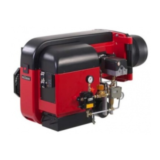
This attached pump spares manual i did not find ( shaft seal,shaft,bush, bearing etc)
The available spare parts for the Oilon RP-130 M pump listed in the context are:- Body- Dosing shaft- Dosing nozzle- O-ring 9.3 x 2.4 Viton- Fitting- Compression spring- Thrust washer- Roller bearing- Spring cotter- Front flange- Hexagonal socket screw- O-ring 45 x 2 Viton- X-ring 10.2 x 2.62 Viton- Ball bearing- Non-return valve- Coupling- Washer- Retaining ring
This answer is automatically generated


Need help?
Do you have a question about the RP-130 M and is the answer not in the manual?
Questions and answers
This attached pump spares manual i did not find ( shaft seal,shaft,bush, bearing etc)
The available spare parts for the Oilon RP-130 M pump listed in the context are:
- Body
- Dosing shaft
- Dosing nozzle
- O-ring 9.3 x 2.4 Viton
- Fitting
- Compression spring
- Thrust washer
- Roller bearing
- Spring cotter
- Front flange
- Hexagonal socket screw
- O-ring 45 x 2 Viton
- X-ring 10.2 x 2.62 Viton
- Ball bearing
- Non-return valve
- Coupling
- Washer
- Retaining ring
This answer is automatically generated