
Related Manuals for Oilon GP-6.10 P


Summary of Contents for Oilon GP-6.10 P
-
Page 1: Gas Burners
OPERATING AND MAINTENANCE INSTRUCTIONS GAS BURNERS GP-6.10 P GP-6.20 P OILON OY P.O.Box 5 FIN-15801 LAHTI FINLAND Tel. +358 3 85 761 +358 3 857 6239 E-mail info@oilon.com 40180036GB... -
Page 3: Table Of Contents
Table of Contents Conventions in this Manual ......................1 General............................2 Burner Technical Data ........................4 3.1. Technical Data ........................4 3.2. Basic Assembly Drawing......................5 3.3. Parts List ..........................6 3.4. Burner Dimensions ......................6 3.5. Nozzle Table ........................6 Burner Installation ..........................7 4.1. Burner Mounting........................7 4.2. Hinged Burner Housing......................7 4.3. -
Page 4: Conventions In This Manual
Conventions in this Manual Read these instructions carefully before installation, commissioning or maintenance of the burner. The given instructions must be followed. Throughout this manual, the following three symbols are used to point out very important information: DANGER! This symbol is used where there may be a danger to personnel, if the instructions are not followed. -
Page 5: General
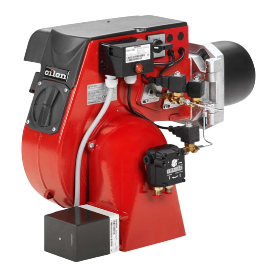
General Oilon GP-6.10 P and GP-6.20 P -burners are fully automatic gas burners. The burners can be used on most heating appliances such as hot water boilers, steam boilers and air heaters. Burners are tested and certified for the following gas types ·... - Page 6 CAUTION! The burner must be installed firmly. Vibrations may damage burner or its components. CAUTION! Prior to trial start the gas piping must be vented. See chapter ”Example of an Installation of Gas Supply Line”. DANGER! In case of gas leakage: - do not make fire, do not touch the electrical equipment - close the main fuel shut-off valve outside the plant - make sure, that there is no people in the leakage area...
-
Page 7: Burner Technical Data
Burner Technical Data 3.1. Technical Data Burner GP-6.10 P GP-6.20 P Capacity kW 50 - 120 60 - 160 Burner motor Voltage 50 Hz 1~ 230 V 1~ 230 V Output kW 0,125 0,125 Current A Speed rpm 2750 2750 Control unit LFL1.322... -
Page 8: Basic Assembly Drawing
3.2. Basic Assembly Drawing 40180036GB... -
Page 9: Parts List
Limit switch (safety switch) Sight glass Protective cover Control switch 3.4. Burner Dimensions Burner Measures in mm Æ D1 GP-6.10 P GP-6.20 P 3.5. Nozzle Table Burner Nozzle (pcs x hole size) Natural gas GP-6.10 P 8 x Æ 4,0 8 x Æ... -
Page 10: Burner Installation
Mounting plate Gasket plate Thermal insulation Æ D2 Burner GP-6.10 P 70 - 74 GP-6.20 P 70 - 74 The mounting plate must have 2 or 4 pcs M10 threaded holes for the mounting of the burner according to the drawing. -
Page 11: Example Of An Installation Of Gas Supply Line
4.4. Example of an Installation of Gas Supply Line The gas supply line after the pressure regulator must be of the same size or one size larger than the valve train size. As standard the gas connection to the burner is from the right side. Note! A hand-operated shut-off valve must be fitted before the gas valve train. -
Page 12: Gas Pressure Regulating Assembly
4.5. Gas Pressure Regulating Assembly If the gas inlet pressure is higher than the Pmax. value given in burner technical data, the gas inlet pressure must be reduced in the regulating assembly or if the gas inlet pressure is not stable, then the pressure must be stabilised by means of the pressure regulator. -
Page 13: Burner Automation
Burner Automation 5.1. Time Sequence Diagram (High-Low) Required input signals to control unit Control signals Permissible input signals to control unit Control loop Servomotor Fan motor Differential air pressure switch Fan pressure 0,4 - 100 mbar Thermostat/pressurestat, partial load PF Combustion chamber pressure -2…+5 mbar Thermostat/pressurestat, full load Burner pressure, gas 0,5 - 100 mbar... -
Page 14: Time Sequence Diagram (Modulating)
5.2. Time Sequence Diagram (Modulating) Required input signals to control unit Control signals Permissible input signals to control unit Control loop Servomotor Fan motor Differential air pressure switch Increase function CC Electronic capacity controller Decrease function Thermostat/pressurestat and/or switch-off threshold of capacity controller Fan pressure, air 0,4 - 100 mbar Increase/decrease functions in cap. -
Page 15: Operation
5.3. Operation Prerequisites for start-up · failures and interlocks are reset · limit switch on burner flange is closed · control switch in position 1 · control unit is reset (lockout indicator at symbol · contact C/NC of differential air pressure switch is closed (air pressure < min) ·... - Page 16 Servomotor has run to switching point III (ignition load) · required start signal from the limit switch of switching point III to the terminal 8 in control unit. Otherwise the start-up program interrupts and the control unit remains (symbol ) waiting for start signal (no failure). Ignition begins ·...
- Page 17 Lockout indicator of the control unit is at symbol · sequence switch stops · fan motor stops · flame simulation tests (LFL) initiate. Lockout due to flame signal with a short delay e.g. - flame not extinguished; leaking fuel valves - faulty flame signal;...
-
Page 18: Burner Adjustments
Burner Adjustments 6.1. Capacity Regulation Gas/air ratio control V Zero point correction N Combustion chamber connection p Fan pressure connection p Gas pressure connection p Gas inlet pressure measuring connection Gas outlet pressure measuring connection Throttle nipple (p Test point connection of intermediate pressure GAS/AIR RATIO CONTROLLER DUNGS MB-VEF…... -
Page 19: Pi-Diagram
6.2. PI-Diagram Gas valve (MultiBloc) Gas/air ratio controller Gas filter Fan pressure connection p Gas pressure switch, min Combustion chamber connection p Main gas valve Gas pressure p Gas valve Valve leak tester (when necessary) 40180036GB... -
Page 20: Combustion Head Adjustments
6.3. Combustion Head Adjustments 6.3.1. Distance between Nozzle and Diffuser Disc and Ignition Electrode Setting The distance between gas nozzle (3) and diffuser disc (2) and the gas nozzle angle (7°) must be set according to the drawing. Also the distance between the ignition electrode (5) and the earth screw as well as the distance between ionization electrode (6) and the burner housing must be set according to the drawing. -
Page 21: Setting Values Of Adjustment Ring
6.3.3. Setting Values of Adjustment Ring Normative setting value of adjustment ring. 1 Flame tube 3 Adjustment ring 2 Diffuser disc 4 Locking screw for the adjustment ring If the position of the adjustment ring has to be altered in relation to the diffuser disc, Note! the air velocity and quantity in the combustion head change. -
Page 22: Combustion Air Adjustment
6.4. Combustion Air Adjustment Set the switching points of cam discs manually or by turning with the adjusting key. Cam discs: Set desired full load. Air damper to ”closed” position. Set desired partial load. 1 Full load adjustment 4 Release lever 2 Air damper closure 5 Adjusting key 3 Partial load adjustment... -
Page 23: Air Cone Position
6.5. Air Cone Position If the air control cone has to be changed or removed, it has to be installed to the right position with respect to the burner housing. The right position is shown in the drawing below. After installation check by turning the fan wheel by hand, that it does not touch the cone. -
Page 24: Pressure Switches
6.7. Pressure Switches 6.7.1. Gas Pressure Switch 1 Adjusting scale 2 Pressure measuring connection 3 Cover Adjust the gas pressure switch (min) on a 20 - 40 % lower pressure than the gas inlet pressure to burner during burner operation at full load. If the gas pressure switch occurs during burner start-up a temporarily burner shutdown, it has to be set on a lower pressure. -
Page 25: Differential Air Pressure Switch
Burner Natural gas Set value Alignment Set value Alignment (mbar) (mbar) GP-6.10 P left arrow left arrow GP-6.20 P left arrow left arrow Adjusting Adjust at the present nominal burner capacity. Open the protective cover of the differential air pressure switch. Start the burner. Turn the switch slowly to the maximum, till the burner shuts down. -
Page 26: Valve Leak Tester Vps 504 (Only On Request)
Valve Leak Tester VPS 504 (only on request) The valve leak tester checks the gas valves for leaks automatically after burner shutdown, when the control unit has returned to its "start-up" position (symbol ) and the control voltage is connected to the valve leak tester. The motor pump increases the gas pressure in the test section. -
Page 27: Control Unit Lfl1.322
Control Unit LFL1.322 8.1. Internal Circuitry Legend Main relay (load relay) with contacts ”ar” Control unit fuse Lockout relay with contacts ”br” Lockout reset button Flame relay with contacts ”fr” Lockout warning lamp Motor of sequence switch Flame signal amplifier NTC-thermistor Mains isolator QRA... -
Page 28: Control Program Of The Sequence Switch
8.2. Control Program of the Sequence Switch Control outputs from terminals Lockout indication a - b start-up sequence operation b - a post-purge sequence (reset of control unit) Switching times (in seconds) of the control program of the sequence switch Pre-purge time safety time Pre-ignition time... -
Page 29: Control Program Under Fault Conditions And Lockout Indication
8.3. Control Program under Fault Conditions and Lockout Indication In the event of fault conditions, the fuel supply is always interrupted immediately and, simultaneously, the sequence switch stops and thus the lockout indicator. The symbol appearing above the reading mark indicates the type of fault. No start, because contacts has not been closed between terminals 12 and 4 or 4 and 5. -
Page 30: Detector Currents And Connection Of Flame Detector Fe (Ionization Electrode)
8.4. Detector Currents and Connection of Flame Detector FE (Ionization Electrode) operation 330 V ± 10 % Electrode voltage test 380 V ± 10 % Short-circuit current max. 0,5 mA 6 mA Min. required detector current Max. possible detector current during operation 150 mA Length of detector line - in the same cable as control lines... -
Page 31: Maintenance
Maintenance DANGER! Always switch off the electric power from your burner and shut the manual shut-off valves in the fuel supply line before servicing your burner. When inspecting your burner you only have to switch off the electric power from your burner. Burner maintenance In order to ensure reliable operation clean the ignition electrodes and check their position. -
Page 32: Fault Conditions And Procedures
10. Fault Conditions and Procedures In the event of fault conditions the basic requirements for correct operation must be first examined: 1. Is the valve leak tester (if any) in operation (yellow indicating lamp is lit)? 2. Check the electric supply. 3. - Page 33 CAUTION POSSIBLE CAUSE REMEDY No flame establishment Burner motor starts, ignition Gas valves do not open: is in order. After a short - blocked pulse lines Clean time lockout occurs. - faulty actuator Replace faulty part - cable damaged - break in control circuit Incorrect gas quantity Adjust Incorrect setting of cam switch...
- Page 34 CAUTION POSSIBLE CAUSE REMEDY Combustion head Diffuser disc burned-out Too low capacity at partial load Adjust Incorrect combustion air Adjust adjustment Boiler room not adequately Increase air supply ventilated Too low combustion air velocity: - incorrect position of adjustment Adjust ring Valve leak tester failure Burner does not start.
-
Page 35: Notes
11. Notes Boiler type ___________________________________________________________ ___________________________________________________________ Burner type ___________________________________________________________ ___________________________________________________________ Burner serial No. Date of installation ___________________________________________________________ Installed by ___________________________________________________________ ___________________________________________________________ Miscellaneous ___________________________________________________________ ___________________________________________________________ ___________________________________________________________ ___________________________________________________________ ___________________________________________________________ ___________________________________________________________ 40180036GB...
Need help?
Do you have a question about the GP-6.10 P and is the answer not in the manual?
Questions and answers