
Related Manuals for Oilon GKP-350 M


Summary of Contents for Oilon GKP-350 M
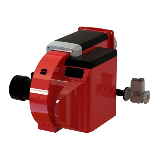
- Page 1 M5178 1647EN 20 December 2016 Operation and maintenance manual GKP-350 M - 450 M WD100, WD200, FGR Read these instructions carefully before installation, use, or maintenance Original instructions...
-
Page 3: Table Of Contents
Contents Introduction Liability disclaimer..................5 Safety precautions..................5 Product overview..................8 Flue gas recirculation (optional)............... 10 Handling and storing.................11 Technical data Burner technical data................12 Profibus module technical data..............13 Flame detector technical data..............14 Burner control technical data..............15 Servomotor technical data................ 17 Display and operating unit technical data..........17 module technical data (WD200)............18 Oxygen sensor technical data (WD200)...........18... - Page 4 4.14 Measuring gas pressure................55 4.15 Operating and display unit menu..............56 4.16 Adjusting operating and display unit settings........... 59 4.17 Setting frequency converter parameters (WD200)........60 4.18 Frequency converter settings and standardization (WD200)....60 4.19 Checking O module (WD200)..............61 4.20 Manual start-up and program stop in pre-purge position......62 4.21 Ignition position..................
- Page 5 6.15 Burner part list..................129 M5178 1647EN 3 (129)
- Page 6 4 (129) M5178 1647EN...
-
Page 7: Introduction
Oilon is unable to accept any liability for damage in case of: ● failure to follow these instructions ● other use than what is explained in this manual ●... - Page 8 Keep these instructions as well as the electrical diagrams available near the device. Oilon products are manufactured according to general product standards and directives, and based on our best knowledge about product design, and technologies. Operation safety is one of the leading principles in our product development. However, it is wise to be prepared, and think about safety.
- Page 9 Do not use Teflon tape in piping. If burner start-up fails consecutively two times, do not restart burner before carefully investigating the reason for the failure. Do not touch hot pipes or surfaces during operation or maintenance. Emergency shutdown In an emergency, cut off power supply to the burner. Close the manual shut-off valves.
-
Page 10: Product Overview
Each burner is tested separately before delivery to the customer. For more information on products, visit our web site at www.oilon.com: Oilon –> Industries –> Product material. 8 (129) - Page 11 Modulating gas, two-stage oil Modulating with a separate fan Label element 4: Additional code, for example burner capacity I-III or automation, like WD34 Type plate The following illustration shows an example of the type plate of Oilon burners: M5178 1647EN 9 (129)
-
Page 12: Flue Gas Recirculation (Optional)
Type plate US ver. 1 Pos. Description Pos. Description Burner type: Degree of protection KP = Light fuel oil RP = Heavy fuel oil GP = Gas GKP = Light fuel oil and gas GRP = Heavy fuel oil and gas Overfire pressure min, IN.WC Serial number Overfire pressure max, IN.WC... -
Page 13: Handling And Storing
1.5 Handling and storing Storing and recycling Store device and its equipment in a dry and airy place. Protect device from dust and humidity. Follow storing and transporting instructions included in the package. Documentation is part of the product, and it must be passed on together with device, also with a second hand product. -
Page 14: Technical Data
2 Technical data 2.1 Burner technical data Burner data Burner GKP-450 M Capacity gas, MMBtu/h 2.90 - 18.77 Capacity oil, MMBtu/h 7.51 - 18.77 Capacity oil, lb/h 408 - 1014 Max. turndown ratio, gas 1:6 (100–16.6%) Max. turndown ratio, oil 1:2.5 (100–40%) Nominal oil pump motor output, hp Motor current A... -
Page 15: Profibus Module Technical Data
Ambient temperature range 0...+ 105 °F Degree of protection NEMA 3 Working diagram Working diagram ver. 3 Working diagram ver. 1 dashed line = oil solid line = gas 2.2 Profibus module technical data Profibus module PBM100 Power supply 24 VDC Power consumption 100 mA Electromagnetic compatibility EMC... -
Page 16: Flame Detector Technical Data
Profibus diagram ver. 1 Terminals may not be connected! CAN/LSB DC power supply (safety extra low voltage) 2.3 Flame detector technical data Supply voltage, operation 14 VDC ±5 % Supply voltage, testing 21 VDC ±5 % Signal voltage 0…5 VDC Power consumption <... -
Page 17: Burner Control Technical Data
QRI connection QRI connection ver. 1 Black X10-02 / 6 Signal line Blue X10-02 / 4 Reference line Brown X10-02 / 2 Power line 2.4 Burner control technical data Burner control LMV5... Mains voltage 120 VAC –15/+10 % Locking during undervoltage conditions <... - Page 18 Block diagram of contact links Block diagram ver. 5 16 (129) M5178 1647EN...
-
Page 19: Servomotor Technical Data
Inputs / outputs (VSD) Connection diagram ver. 3 2.5 Servomotor technical data Servomotor SQM45... SQM48.497 SQM48.697 Mains voltage 2 x 12 VAC 2 x 12 VAC 2 x 12 VAC Power consumption 9 – 15 VA 26 – 34 VA 26 –... -
Page 20: O 2 Module Technical Data (Wd200)
2.7 O module technical data (WD200) module PLL52... Mains voltage, sensor heating 110 VAC –15/+10 % Mains voltage 2 x 12 VAC Power consumption 4 VA Analog inlet, oxygen sensor QGO20.000D27 Analog inlet, combustion temperature Pt1000 / LG-Ni 1000 Analog inlet, flue gas temperature Pt1000 / LG-Ni 1000 Analog inlet, bus interface Protection degree... -
Page 21: Installation
3 Installation 3.1 Space requirements Leave enough space on each side of the burner for installation, commissioning, and maintenance purposes. The minimum space requirements are presented in the following. Installation, commissioning, or service of the appliance is to be carried out by authorized and trained personnel only, adhering to all local regulations and requirements. - Page 22 The burners are attached and supported to a transportation base. The base can be lifted from all sides with a forklift. When lifting the package, the center of gravity must be in the middle between the forks to avoid falling. Use hexagonal key to remove and attach protective covers.
-
Page 23: Mounting Burner
Burner Lifting lug (1 pcs) Lifting eyes (2 pcs) Lifting straps Lifting hook ... - Page 24 Burner mounting dimensions (mm) D042664 ver. 1 Burner Dimensions in mm 450 M 1470 350 Burner Dimensions in inch 450 M 57.87 13.78 13.46 7.60 13.19 30.31 11.97 15.55 4.92 19.69 25.59 21.65 14.57 22 (129) M5178 1647EN...
- Page 25 Combustion head mounting dimensions øD4 D042316 ver. 3 Pos. Item Pos. Item Gasket, 10 mm / 0.39 in Ceramic wool or similar Mounting plate, 20 mm / 0.39 in Refractory Burner Dimensions in mm Fastening screws 450 M Burner Dimensions in inches Fastening screws...
-
Page 26: Gas Valve Selection Table
3.4 Gas valve selection table BURNER GAS VALVE BURNER CAPACITY RANGE kW GAS INLET PRESSURE SIZE TYPE 20 mbar 30 mbar 50 mbar 100 mbar 150 mbar 350 M DN 50 DMV-D 1700 2200 3100 3800 DN 65 2000 2500 3300 4400... -
Page 27: Installing Gas Pressure Regulating Assembly
B352U ver. 3 ● Install gas pipings according to the regulations of local public authority. ● Check that there is a separate filter before gas equipment. ● Prior to installing gas pressure regulator block to piping, use compressed air to blow supply piping clean. ●... - Page 28 Installing safety relief valve and safety shut-off valve Check that the safety relief valve is dimensioned so that the safety shut-off valve does not release if the burner shuts down at full load. The burner may be shut down, for example, due to mains interruption.
-
Page 29: Installing Gas Nozzle Adjusting Band (Lpg)
Pos. Item Pos. Item Pressure regulator with safety shut-off Pressure gauge, high pressure, when valve and safety relief valve necessary Pressure gauge valve Fuel flow meter, can also be on low pressure side, when necessary Pressure gauge, low pressure Pressure regulator 3.7 Installing gas nozzle adjusting band (LPG) This information applies only when liquified petroleum gas (LPG) is used. -
Page 30: Installing Hoses
3.8 Installing hoses Avoid torsion stress on hoses Leave neutral hose ends long enough Use rigid pipe bends when necessary Minimum bend radius Hose diameter Minimum bend radius ( r ) Minimum bend radius ( r ) Ø 12 130 mm 5.12 in Ø... -
Page 31: Oil Supply Site Diagram, Example
3.9 Oil supply site diagram, example Diagram B-528V ver. 1 Pos. Item Details Pos. Item Details Filter 400 µm Filter 125 µm Pressure gauge cock Pressure gauge cock Pressure gauge Max. low pressure Pressure gauge Oil pressure 1 - 5 bar -0,3 bar Filter 250 µm... -
Page 32: Connecting To Oil Line
3.10 Connecting to oil line Two-pipe system The burner is equipped for two-pipe system. Two-pipe system has separate suction and return lines for oil. Fit oil filter according to PI diagram. Pay attention to the instructions provided by the pump manufacturer when dimensioning the pipeworks. - Page 33 In monoblock burner constructions, pos. 3 and 4 are integrated parts of the burner. Burner model Minimum diameter Minimum diameter of FGR pipe of FGR pipe Group 4 Inches 350 M 6” 450 M 8” Designing FGR piping When designing the piping, consider the special circumstances of FGR operation. The temperature in the piping varies constantly during the operation causing expansion and contraction of the pipes.
-
Page 34: Electrical Connections
Installing temperature sensor D055288 ver. 1 Temperature sensor Butterfly valve FGR pipe (*) Burner Sleeve (*) Min. 200 mm Min. 7.87 in * not included in delivery 3.12 Electrical connections Connect burner according to the electrical diagrams delivered with burner. Adhere to general and local standards and regulations as well as requirements set on the connections of electrical equipment. - Page 35 ● When using frequency converter, do cabling work and grounding according to manufacturer instructions. ● Locate frequency converter as near to motor as possible to avoid interference caused by long cabling. ● Separate supply cables from control and bus cables in cable rack if they cannot be installed in separate cable racks.
-
Page 36: Commissioning
4 Commissioning 4.1 First start-up Vent fuel lines before first start-up. After the first start-up check the cleanliness of the filter weekly and replace if necessary. If the filter remains clean, inspection period can be extended to one month. Pump must not operate without oil. Vent the oil pump before initial start- up and when changing the pump. -
Page 37: Nozzle Selection
To start the burner: 1. Open the fuel shut-off valves. 2. Switch on power supply. 3. Switch on the burner from the burner control switch. To stop the burner: Turn the burner control switch to OFF position. 4.2 Nozzle selection Fuel consumption by boiler capacity P = boiler capacity, kW µ... - Page 38 When using any other oil pump pressure as shown in table, the throughput of nozzle is: PAINEKAAVA1 ver. 2 A = Table value P1 = 20 bar (Fluidics) P2 = Oil pump pressure For example: nozzle 12-W1 No. 100, oil pump pressure 30 bar (3,0 MPa) ⇒ throughput of nozzle is: 30 bar Max.
- Page 39 Nozzle No. Max. throughput kg/h at oil pump pressure of Min. throughput kg/h at oil 25 bar (2,5 MPa) when return line is closed pump pressure of 25 bar (2,5 MPa) when return line pressure is 7 - 10 bar (0,7 - 1,0 MPa) When using any other oil pump pressure as shown in table, the throughput of nozzle is PAINEKAAVA1 ver.
- Page 40 Oil pump operating pressure (atomizing pressure) in light fuel oil is 2000 - 2500 kPa (20 - 25bar). Spill return nozzle Bergonzo CBM B5 AA Table is applicable when atomizing viscosity is 12 mm²/s (cSt) Nozzle No. Max. throughput kg/h at oil pump pressure of Min.
-
Page 41: Adjusting Combustion Head
4.3 Adjusting combustion head Combustion head components D042327 ver. 1 Pos. Item Combustion head Diffuser disc Adjustment ring Ignition electrode Gas nozzle Ignition gas nozzle Oil nozzle 8 mm 0.31 in 4.4 Setting ignition electrodes Check and set ignition electrode spark gap and the distance of the nozzle to ignition electrodes and diffuser disc as shown on the drawing. -
Page 42: Adjusting Supply Oil Pressure
Maximum tightening torque of ignition electrodes is 1 Nm. D042321 ver. 1 10 mm 0.39 in 9 mm 0.35 in 3 mm 0.12 in 4.5 Adjusting supply oil pressure In light fuel oil burners inlet pressure should be 1–4.5 bar or 14.5–65.3 PSI. - Page 43 2. Let the burner operate for a while. Air bubbles come out of the hole. 3. When no more bubbles come out, retighten the plug carefully. If the atomizing pressure during capacity change from max. to min. exceeds 2 bar / 29 PSI the pump must be replaced. The pump is self-priming.
- Page 44 Technical data Max oil inlet pressure to burner 5 bar 72.5 PSI Inlet oil viscosity range 4–70 mm²/s (cSt) 4–70 mm²/s (cSt) Min oil inlet pressure to burner 2.5 bar or higher 36.25 PSI or higher (Depends on oil temperature at the pump.) Inlet oil maximum temperature + 150 °C + 302 °F...
- Page 45 Oil pump TA A212ZTA ver. 3 Pos. Item Pos. Item Oil suction connection Protective cap Oil to nozzle Oil inlet pressure/gauge port Oil return connection Pressure gauge connection plug / air venting Pressure adjustment Opening for bypass plug Pump has an integrated pressure regulation system. Technical data Operating viscosity 3–75 mm²/s (cSt)
-
Page 46: Adjusting Atomizing Pressure
Oil pump TAR A212ZTA ver. 3 Pos. Item Pos. Item Oil suction connection Protective cap Oil to nozzle Oil inlet pressure/gauge port Oil return connection Pressure gauge connection plug / air venting Pressure adjustment Opening for bypass plug Pump has an integrated pressure regulation system. Technical data Operating viscosity 1.25–75 mm²/s (cSt) -
Page 47: Oil Pump Coupling Components And Adjusting
TVSAADINDANFOSS ver. 3 TVSAADIN ver. 2 Regulator valve option 1 Regulator valve option 2 Pos. Item Pos. Description Protective cap Oil from pump Pressure regulation Oil to nozzle Pressure gauge connection Return oil 4.8 Oil pump coupling components and adjusting Oil pumps J, E, PON, TAR, T, TA and UHE A296X ver. -
Page 48: Adjusting Combustion Differential Air Pressure Switch
Oil pump AFI BOWEX ver. 3 Pos. Item Sleeve Set screw Set the distance between the hubs. See the image. Note the correct direction of the hubs. 4.9 Adjusting combustion differential air pressure switch Combustion differential air pressure switch The combustion differential air pressure switch monitors pressure difference generated by burner fan. - Page 49 Higher pressure Lower pressure Electrical connections Setup switch 1 and 2 cross head screw LGW A2 ver. 2 If pressure difference does not rise above switch setting value, burner shuts down. Differential air pressure switch should be set to trigger before CO-concentration of combustion product exceeds 1 vol%, 10 000 ppm.
-
Page 50: Adjusting Gas Pressure Switch
4.10 Adjusting gas pressure switch Gas pressure switch, max. 1 Adjusting scale 2 Reset, gas pressure switch, max. 3 Pressure measuring connection A416M ver. 3 Gas pressure switch max. should cause a permanent interlocking if burner capacity increases to be more than 1.15 times the nominal value, or if the pressure exceeds more than 1.3 times the nominal pressure. -
Page 51: Setting Variable Speed Module Parameters
4. Slowly turn the gas pressure switch towards its minimum setting until the burner shuts off. The pressure switch is now correctly configured. 5. Reset the error. 6. Decrease gas pressure to normal value. Check combustion values. To adjust gas pressure switch, min. Burner size Factory setting mbar Factory setting PSI... - Page 52 DIP 4–7, select sensor input DIP4 DIP5 DIN6 DIN7 Input/ value range Namur sensor 600-7200 pls/Min Namur sensor 300-3600 pls/Min 3-wire sensor 30-300 pls/Min 3-wire sensor 600-7200 pls/Min 3-wire sensor 300-3600 pls/Min Current input 0-20 mA Current input 4-20 mA DIP 8, setpoint output DIP8 Setpoint output...
-
Page 53: Setting Gas Pressure Regulator Skp
The operating area of the gas pressure regulator is determined by the spring installed inside the pressure regulator. There are three types of springs and their operating areas are described in the table below. Springs can be ordered from Oilon Webshop. M5178 1647EN 51 (129) - Page 54 SKP ver. 1 To change spring: 1. Remove the plug. 2. Remove the slot-head screw by turning counter-clockwise with a chisel-point screwdriver. 3. Replace the spring. Assemble in reverse order. Excessive tightening of screws may damage the component. Spring type pG (mbar) ∆p / Color...
-
Page 55: Setting Gas Pressure Regulator Frs
The factory setting of standard spring p is 10-30 mbar. Springs can be ordered from Oilon Webshop. Setting pressure regulator at minimum load 1. Start burner at minimum load. At minimum load throttle valve setting is 5°-10°. - Page 56 To adjust outlet pressure 219598a ver. 1 1. Unscrew protective cap A. 2. Use a chisel-point screwdriver. to adjust spindle B: a. Turn the spindle B clockwise. This increases the outlet pressure. b. Turn the spindle B counterclockwise. This reduces the outlet pressure. 3.
-
Page 57: Measuring Gas Pressure
FRS4 ver. 2 Protecting cap sealing hole, ø 1.5 mm Body sealing hole, ø 1.5 mm Setpoint Color Nominal width Rp/DN spring range (mbar) Rp 1 1/2, Rp 2, DN Rp 2 1/2, DN 100 DN 125 DN 150 DN40 DN65, 80 Spring 1... -
Page 58: Operating And Display Unit Menu
Measuring nozzle pressure 1. Nozzle pressure at nominal capacity Burner Test point 1 Test point 1 (mbar) (in.Wc) 450 M 11.2 4.15 Operating and display unit menu Menu structure Menus are divided into two user levels. First user level is User, and it does not require password. Second user level is Service. - Page 59 OilStage1/Mod Hours run oil stage 1 or modulating (selectable) OilStage2 Hours run oil stage 2 (selectable) OilStage3 Hours run oil stage 3 (selectable) TotalHoursReset Hours run total (can be reset) TotalHours Hours run total (read only) ...
- Page 60 GatewayBASoff Deactivating the eBus port Type of Gateway O2Ctrl activate O2 trim controller activated/deactivated Manual operation User can scroll through and change manual operation settings from operating and display unit. Description ManualOperation ...
-
Page 61: Adjusting Operating And Display Unit Settings
Servomotors ● Addressing ● DirectionRot ● SW Version ● ProductID VSD Module ● Configuration ● Process Data ● ProductID ● SW Version 4.16 Adjusting operating and display unit settings Scrolling menus For scrolling and changing set values of the operating and display unit menu, use the four buttons on the panel. -
Page 62: Setting Frequency Converter Parameters (Wd200)
Activating safety check function Description SafetyCheckFunct LossFlameTest Loss of flame test SLT test Safety limit thermostat test Burner lockout function is triggered by pressing the Enter and Esc buttons simultaneously. 4.17 Setting frequency converter parameters (WD200) Parameters for frequency converter used for fan motor control must be set before the first start-up. -
Page 63: Checking O Module (Wd200)
Params. & Display VSD Module Configuration Speed Num Puls per R Standardization StandardizedSp ... -
Page 64: Manual Start-Up And Program Stop In Pre-Purge Position
Description Params. & Display O2 Module Displayed Values Actual O2 Value Actual O2 Value O2 Setpoint O2 Setting SupplyAirTemp Supply air temperature in °C /... - Page 65 Pre-purge position phase 24–34 Ignition position phase 36 Transition 1 phase 44 Transition 2 phase 52 Post-purge phase 72–78 Active program stop in phase 24. Params & Display Ratio Control Program Stop ...
-
Page 66: Ignition Position
Param. & Display RatioControl GasSettings Special- Positions Pre-purgePos Pre-purgePos- Pre-purgePos- Aux1 ... - Page 67 ● gas is selected as fuel, and it is the first start-up ● burner control has been unenergized ● it has been a long time from previous shutdown ● it is a start-up after safety shutdown or lockout reset During standard stop, valve leak test is carried out before pre-purge period. 1.
-
Page 68: Setting Ratio Curve
4.22 Setting ratio curve Curve points There can be 15 curve points at the maximum. Set curve points in the following menu level: Params. & Display RatioControl GasSettings CurveSettings ... - Page 69 If you want to set a new curve point, press Enter, when XXXX is displayed as set value. The ignition position will automatically be the first ratio curve point, from which the burner minimum load point is adapted. Editing individual curve point To change the existing curve point: 1.
- Page 70 Press Enter at the desired parameter. Curve point 6 ver. 3 Change setting using the Select -/+ buttons. Then servomotors drive to their new position. During that time the display shows ">" instead of ":". Confirm the change by pressing Enter or undo by pressing Esc. Then you return to the previous menu level. The servomotor turning angle is 0…90°...
- Page 71 Curve point 8 ver. 3 2. Press Enter, and use the Select -/+ buttons to increase or decrease burner start capacity. Curve point 9 ver. 3 3. Servomotors follow imaginary linear towards maximum or minimum load. Oxygen value can be monitored from display. When increasing load, monitor that combustion values do not increase to a hazardous level.
-
Page 72: Activating Fgr
Middle points are set manually by decreasing load manually for example in 10% distances. Note that residual oxygen level is sufficiently over aired if the burner is equipped with O trim control. Oxygen residual level is set 1% higher than the normal level. -
Page 73: Setting Fgr Curve Points
4.24 Setting FGR curve points The FGR curve points are set at the fuel-air ratio curve. During the time the curve menu is in use, the state of the FGR function does not change. This means that if the AUX3 is still at the ignition position when setting parameters, it maintains the position until the curve setting is completed. -
Page 74: Measuring Fgr
Changing curve settings may have an impact on the combustion settings. Check the servomotors regulating fuel and air. Readjust if needed. You can save changes to the operating and display unit memory. Answer yes to the screen message that appears when leaving Params. & Display menu level. For more detailed instructions on setting, monitoring, and editing curve points, see section Setting ratio curve. -
Page 75: Capacity Range
To define flue gas percentage 1. First measure the amount of O in the flue gas/combustion air mixture. The optimal measuring point is the burner wind box. 2. Measure the residual O in flue gas. 3. Read the FGR percentage value in the diagram below. Natural gas combustion, Flue Gas Recirculation 20 %... -
Page 76: Min. Value Control (Wd200)
LoadLimits MinLoadGas. Minimum load "Low fire" (gas) MaxLoadGas Maximum load "High fire" (gas) On user level, maximum load can be set individually as follows: Description Operation ... - Page 77 Hazardous conditions must not permanently occur above or at O min. value. Maximum permitted values: CO = 4000 ppm, #2 on the Shell-Bacharach scale. Values may vary depending on the type of plant. If the ratio curves are changed later, min. value must also be readjusted.
-
Page 78: Setting O Trim Control (Wd200)
min. value surface is verified by throttling air and measuring CO level at the same time. 4. When desired oxygen level is reached, accept the value by pressing Enter. Exit by pressing Esc. Repeat for each curve point. Start setting O ratio control after O min. - Page 79 Point22 ver. 3 4. Display the changes. The third line shows the current residual oxygen level. The pointer is on StandardVal. Reduce the air by pressing the Select -/+ buttons, if necessary. Larger level at this point, means larger air throttle. When desired oxygen level is reached, press Enter.
-
Page 80: Trim Control Operating Mode (Wd200)
4.29 O trim control operating mode (WD200) Select the suitable O trim control operating mode as follows: Params. & Display O2Contr/Guard FuelSettings OptgMode auto deact ... -
Page 81: O 2 Trim Control When Load Changes (Wd200)
Params. & Display O2Contr/Guard Fuel settings O2CtrlThreshold Apadt.Point small Type of Fuel Fuel user def If load drops below this limit, the burner operates along parameterized ratio curves without O trim control. Set load limitation after setting O trim control ratio curve. Load limitation is usually curve point 2 load from basic parameterized ratio curve. - Page 82 Description Operation BoilerSetpoint SetpointW1 Internal setpoint W1, °C / °F Internal setpoint W1, bar / PSI 2. Select burner start-up manually by activating Autom/Manual/Off option Autom. Preset value from burner control is IntLC. ManualOperation ...
-
Page 83: Setting Capacity Controller Parameters
4.33 Setting capacity controller parameters Standard parameter setting Capacity controller contains 5 standard parameter settings that can be selected and activated, depending on characteristics of controlled process. Params. & Display Load- Controller ... - Page 84 P -Part (Xp) I -Part (Tn) D -Part (Tv) ● By increasing the proportional band, the temperature/pressure deviation is lowered. Using too great a proportion will result in temperature/pressure fluctuation. ●...
- Page 85 Flow chart_WD capacity ver. 2 trim control must not be active during adaptation. In the WD200 system, deactivate O trim control from the operating and display unit menu: Operation O2Ctrl activate deactivated activated Select StartAdaption. Parameter evaluation Capacity control does not cause variation in boiler temperature or pressure with optimum PID parameters.
- Page 86 Practical value for Tn / Tv = 4…6. Examples of typical incorrect settings, and the optimal setting to change the set value: Xp too high Xp too low Tn and Tv too low Tn and Tv too high Optimum setting If load control is not completely stabilized, but fluctuates continuously near the setpoint value, the following parameters can be used to control this.
-
Page 87: Capacity Controller On/Off
SW_FilterTimeCon. can be used to delay the internal load controller. If the value for this parameter is too high, the internal load controller becomes unstable. The factory setting is 3s. 4.34 Capacity controller on/off If temperature or pressure has been given a set value, burner start-up and shut down limits are percentages of the set value. -
Page 88: Cold Start Thermal Shock Protection
Limiter switch-on point 80 °C TL_ThresholdOff 176 °F Temperature difference percentages -10 % (=8 °C) TL_SwiDiff_On -10 % (46.4 °F) Limiter reset temperature 72 °C 161.6 °F Description Params. & Display LoadController ... -
Page 89: Measuring Flue Gas And Combustion Air Temperature (Wd200)
Cold start thermal protection operation example. KYLMAKAYNNISTYS ver. 3 4.37 Measuring flue gas and combustion air temperature (WD200) Flue gas and combustion air temperature measuring sensor can be connected to O module. Alarm for high flue gas temperature can be set individually for both fuels. Select the sensor type and set the alarm threshold from the menu as follows: ... -
Page 90: Backing Up Parameters
Operation O2Ctrl activate deactivated activated 4.39 Backing up parameters 1. Start backing up parameters by selecting following from the display and operating unit: Updating ParamBackup BackupInfo LMV5x –> AZL ... -
Page 91: Operation
5 Operation 5.1 Burner operation WiseDrive 100 / 200 LMV operation ver. 4 The assembly may vary depending on the scope of delivery. In the WiseDrive system, burner operation is controlled and supervised by an integrated burner control. In the WD200 system, the burner can be equipped with O module to increase combustion efficiency. - Page 92 Burner control Burner controller is a microprocessor-based burner control and safety system. Burner control can have the following features: ● Burner control and safety functions ● Electronic fuel/air ratio ● Gas valve proving ● Capacity controller ● Fan frequency converter control (WD200) ●...
- Page 93 Combustion air Combustion air provides the needed air pressure and volume for efficient combustion. In the WD200 system, the fan motor can be fitted with a variable speed drive. The variable speed drive adjusts air pressure according to burner’s capacity by controlling the fan speed.
-
Page 94: General Description Of Burner Operation
Oxygen sensor (WD200) Oxygen sensor measures the amount of residual oxygen from flue gas. The sensor is a ceramic zirconium dioxide cell and self-testing. QG020 ver. 3 Flame detector QRI is a flame detector for use with gas, oil and other flames that emit infrared light. Flame signal intensity can be monitored on display. - Page 95 If burner shuts down, solenoid valves (NC) close and control flow oil pressure releases from nozzle valve. Nozzle valve spring power closes nozzle needle valve and oil supply from nozzle. Post-purge The post-purge position of servomotors is adjusted according to the fuel type. After burner shutdown, servomotors drive to their post-purge positions.
-
Page 96: Gas Valve Proving
5.3 Gas valve proving Valve proving system is carried out with pressure switch that supervises piping section between valves. Burner control opens and closes gas valves during proving according to the programmed times. If leak is detected, gas valve proving function prevents gas valves from opening, and ignition from beginning. - Page 97 Prepurge time (tv1) Postpurge time (tn1) Prepurge time (tv) Flue gas recirculation postpurge position Prepurge time (tv2) (flue gas recirculation ARF) 78 Postpurge time (tn3) Ignition position Direct start Preignition (Z) ON Valve proving evacuating time Burner valve ON Valve proving time atmospheric pressure Ignition OFF Valve proving filling time Interval 1 (ti1)
- Page 98 Symbols: Signal ON Signal OFF Next phase 00, repetition = 0 01 12, repetition > 0 Parameter NormalDirectstart Checking with controller ON Deviation → 10 No repetition decrement Without valve proving → 70 With valve proving → 80 ...
- Page 99 Param.: Normal / continuous purge Normal purge: Checking for OFF in 10 and 12, stop to phase-max time → 01 Continuous purge: Checking for ON in 10 and 12, stop up to phase-max time → 01 Param.: OilPressureMin, act from ts → no check before first safety time (LO, HO) or second safety time (LOgp, HOgp) Param.: GasPressureMin, deact xOGP→...
-
Page 100: Time Sequence Diagram, Gas Use
5.5 Time sequence diagram, gas use Time sequence diagram, G ver. 3 98 (129) M5178 1647EN... - Page 101 Time sequence diagram, Gp1 ver. 5 M5178 1647EN 99 (129)
-
Page 102: Burner Automation Description, Gas Use
Time sequence diagram, Gp2 ver. 2 5.6 Burner automation description, gas use Time sequence phases Prerequisites for start-up ● Fuel selector switch in position 2 (gas). ● Failures and interlocks reset. ● Limit switch on burner flange closed. ● Safety loop closed. ●... - Page 103 20, 21 Start-up ● Burner control safety functions activate. ● Gas safety valve opens (optional). ● Gas pressure recognition, pressure switch min. closed. ● ”Gas start release” closed (optional ). 22 Fan motor starts 24 Servomotors drive to pre-purge position ●...
- Page 104 54 Servomotors run to min. capacity 60 Operation ● Burner control in automatic operation: burner control capacity controller adjusts burner capacity on modulating range to correspond to the load by controlling air dampers, gas regulator and fan motor rotation speed. Burner operates controlled by burner control and capacity controller according to set parameters and functions.
-
Page 105: Time Sequence Diagram, Oil Use
5.7 Time sequence diagram, oil use Time sequence diagram, LO ver. 5 5.8 Burner automation description, oil use Prerequisites for start-up ● All malfunctions and lockouts must be reset. ● Burner flange limit switch must be closed. ● Safety switch circuit must be closed. ●... - Page 106 ● Main unit must be set to either manual use or automatic use. If automatic use is selected, the capacity controller must also be switched on. ● Remote start-up circuit contacts must be closed ● Boiler thermostat / pressure switch contacts must be closed. 20, 21 Start-up ●...
- Page 107 ● Lockout, if fan contactor contact opens or fan motor rotation speed signal disappears during burner operation. ● Lockout, if servomotors do not reach the defined position during operation. ● Lockout, if the Esc and Enter buttons on the operating and display unit are pressed simultaneously during operation.
-
Page 108: Maintenance
6 Maintenance 6.1 Burner maintenance Installation, commissioning, or service of the appliance is to be carried out by authorized and trained personnel only, adhering to all local regulations and requirements. Fasten all safety covers, enclosures, and guards with all screws before start-up. -
Page 109: Dismounting Combustion Head
● When ordering spare parts, give the burner type and serial number indicated on the burner type label or manufacturing card. If you need help with maintenance issues, contact your nearest representative or Oilon customer service at http://www.oilon.com/customer-service/. Burner contains electric and electronic components. Adhere to rules and regulations from local authorities when disposing. -
Page 110: Dismounting And Changing Burner Motor
Pos. Item Gas nozzle fastening screws Combustion head Combustion head fastening screws Check that gas nozzle is centralized in relation to the adjustment ring. Check O-ring when assembling. Change if necessary. 6.3 Dismounting and changing burner motor Cut off electricity from burner and ensure the motor has no voltage. Fan cross section Motor Fan wheel... -
Page 111: Dismounting And Changing Servomotors
4. Screw off screws in the motor mounting flange and lift the motor away. 5. Screw off the fan wheel fixing screw and fixing sleeve. 6. Pull out the fan wheel from motor shaft using an extractor. 7. Loosen the wedge and base bushing. To mount motor and fan wheel: 1. - Page 112 Pos. Item Pos. Item Servomotor Shaft coupling aligning screw and clamping screw Servomotor fixing screw Butterfly valve DMK-Q Shaft coupling Aligning surface of servomotor’s shaft 1. Disconnect the cables according to the instructions. 2. Loosen the clamping and aligning screw of the shaft coupling (shaft coupling stays on butterfly valve’s shaft) 3.
- Page 113 7. Place the new servomotor. 8. Tighten the servomotor fixing screws. 9. Connect the cables according to the instructions. Removing the air damper servomotor D031517 ver. 1 Pos. Item Pos. Item Servomotor Shaft coupling aligning screw Servomotor bracket Shaft coupling clamping screw Shaft coupling Servomotor fixing screw 1.
- Page 114 Removing regulating unit motor D033674 ver. 1 Pos. Item Pos. Item Servomotor Shaft coupling Servomotor fixing screw Shaft coupling aligning screw Servomotor shaft and aligning level Shaft coupling clamping screw 1. Disconnect the cables according to the instructions. 2. Loosen the clamping and aligning screw of the shaft coupling; shaft coupling stays on regulator valve shaft.
-
Page 115: Oil Filter
6.5 Oil filter A525G ver. 4 Pos. Item Pos. Item Filter housing Filter element Filter cover Washer O-ring O-ring Gasket Plug Hexagon head plug Hexagonal screw Gasket Oil to filter Spring Oil to burner Make sure that oil viscosity is low enough for successful maintenance. To clean the filter: 1. -
Page 116: Nozzle Valve Operation And Maintenance Rpl-1
10. Make sure that the O-ring (3) is properly placed and put the cover (2) on. 11. Fasten the cover (2) with hexagonal screw (6) to a torque of 25–30 Nm. 12. Open fuel supply valves. 6.6 Nozzle valve operation and maintenance RPL-1 Nozzle valve RPL-1 components B384E ver. -
Page 117: Oil Regulator
RPL-1 Operation principle The opening of the nozzle valve is controlled by solenoid valves and oil pressure. The force of oil pressure on piston must exceed the force of the spring. The pressure of the spring closes the nozzle valve, when oil pressure stops having effect on nozzle valve. The needle valve of the nozzle closes. -
Page 118: Testing Safety And Control Devices
Oil regulator components for models 300 - 600 D033714 ver. 1 Pos. Item Pos. Item Body O-ring Dosing shaft Needle bearing Dosing nozzle Retaining ring Nipple Retaining ring Spring Switch/scale Thrust washer Hexagon socket grub screw Roller bearing Connector Spring cotter Washer Front flange Hexagon socket-head screw... - Page 119 ● servomotors ● O /CO trim control (if equipped) ● boiler safety devices Flame detector Test method Outcome Step 1 The burner must shut down and lockout at the end 1. Prevent any light from reaching the detector and of safety time. Error code 25 and the text No flame start the burner.
- Page 120 Test method Outcome Boiler pre-purging begins. The burner Step 1 1. Rotate the setting wheel on the switch to its maximum must shut down before the pre-purge value. cycle is completed. 2. Start the burner. Error code 2F and the text Gas Pressure After testing, return the setting wheel to its original position and has dropped below minimum Limit reset the switch.
-
Page 121: Fault And Lockout History
Servomotors During burner start-up the burner control drives the servomotors to maximum position and during shutdown to 0-position. The burner control supervises the correlation of the position settings and back coupling. During burner shutdown, check the air damper and the locking screws of the fuel adjusting valve. - Page 122 Burner failure can also be reset by pressing burner failure reset button on the control panel longer than 1 s, or by giving a remote reset signal. Pressing of burner failure reset button during burner operation causes a lockout. Button is also used as emergency stop button. Fault history stores the last 21 error messages.
-
Page 123: Frequency Converter (Wd200)
For more detailed information about fault and lockout codes, refer to Basic Documentation LMV5. 6.10 Frequency converter (WD200) Frequency converter is started and stopped using potential-free release contact in burner control. Frequency converter alarm is connected to burner control with 12…24 VDC voltage signal that causes burner safety stop. -
Page 124: Troubleshooting
EU density test 1 ver. 3 US density test 1 ver. 2 Result: Test time is 7 seconds. EU density test 2 ver. 3 US density test 2 ver. 2 Result: Leakage rate is 45,7 l/h / 1.6 cf/h. 6.12 Troubleshooting Before troubleshooting check section First start-up If the fault can not be found in the First start-up, check the individual burner functions. - Page 125 Start failure Condition Possible cause Action Burner does not start. Burner Break in control loop. Find out the cause of the break. control remains in stand-by Required start-up signal from position. Set temperature or burner control terminal X5-03.4 pressure too low. does not transfer to terminal X5-03.1.
- Page 126 Leakage test failure Condition Possible cause Action Leakage test failure Gas block failure See section Gas valve proving. Gas inlet pressure to burner too Find out cause and repair. Faulty pressure switch Change. Faulty gas valve Change. No ignition spark Condition Possible cause...
- Page 127 Flame does not form Condition Possible cause Action Fuel valves do not open or open Gas or oil use: Fan motor starts, ignition spark too slowly: is in order. After a short period of time lockout occurs. Break in control circuit. Find out cause of the break.
- Page 128 Lockout occurs after flame establishment Condition Possible cause Action Flame forms. Occurs lockout. Gas pressure unstable. Check and repair. Incorrect burner adjustment Adjust. When burner runs to full load, Gas pressure too low because Check operation and regulations. flame extinguishes, shutdown min.
-
Page 129: Troubleshooting Error Codes
Poor combustion CONDITION POSSIBLE CAUSE ACTION Poor oil atomizing. Oil atomizing or return pressure Check and adjust. too low. Nozzle spraying angle incorrect. Try nozzle with a different spraying angle. CO-content is too high or smoke Pressure drop in combustion head Adjust pressure drop. -
Page 130: Burner Parts
6.14 Burner parts Exploded view D054888 ver. 1 The assembly may vary depending on the scope of delivery. Gas valve FGR ver. 2 VGD40... ver. 1 Gas line for pilot burner optional 128 (129) M5178 1647EN... - Page 131 6.15 Burner part list Recommended change interval Part name 1–2 3–5 on demand/ year years years start-up max. Protective cover Flange gasket Fan motor Diffuser disc Gas nozzle ...
- Page 132 130 (129) M5178 1647EN...
- Page 134 Contact information of Oilon dealer: OILON GROUP P.O. Box 5 FI-15801 LAHTI FINLAND Tel: +358 3 85 761 Fax: +358 3 857 6239 Email: info@oilon.com Date of installation: www.oilon.com...
Need help?
Do you have a question about the GKP-350 M and is the answer not in the manual?
Questions and answers