
Related Manuals for Oilon KP-6


Summary of Contents for Oilon KP-6
- Page 1 OPERATING AND MAINTENANCE INSTRUCTIONS LIGHT OIL BURNERS KP-6 KP-6 L KP-6 LH KP-6-2 KP-6 H-2 OILON OY P.O.Box 5 FIN-15801 LAHTI FINLAND +358-3-85 761 +358-3-857 6239 20039847GB E-mail info@oilon.com...
-
Page 2: Table Of Contents
6.2. 1-Stage Burner with Preheater, KP-6 L................13 6.3. 2-Stage Burners (H-Burners), KP-6 H-2 ................15 6.4. 2-Stage Burner (”H” Burner) with Preheater, KP-6 LH ............15 Burner Automation........................17 7.1. 1-Stage Burners ........................ 17 7.2. 2-Stage Burners (H-Burners) .................... 19 Burner Adjustment........................ -
Page 3: Conventions In This Manual
Conventions in this Manual Read these instructions carefully before installation, commissioning or maintenance of the burner. The given instructions must be followed. Throughout this manual, the following three symbols are used to point out very important information: WARNING! A warning alerts you to possible danger to person, if the instructions are not followed. -
Page 4: General
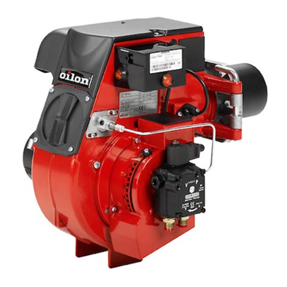
General Oilon KP-6...KP-6 H-2 burners are fully automatic light oil burners. These burners can be used on most heating appliances such as hot water boilers, steam boilers and air heaters. A fan attached to the burner and dimensioned to provide a sufficiently high and even air pressure for efficient combustion in modern combustion chambers delivers the required air. - Page 5 CAUTION! The burner must be installed firmly. Vibrations may damage burner or its components. Prior to first start-up the oil pump must be vented. The pump must not CAUTION! operate without oil. See chapter ”Oil Pumps”. WARNING! In case of fire or other danger: switch off the main switch close the main fuel shut-off valve outside the plant take appropriate actions.
-
Page 6: Burner Technical Data
700 - 1400 kPa (7 - 14 bar) (1-stage burners) • 700 - 2500 kPa (7 - 25 bar) (2-stage burners) ● standard version equipped for two-pipe system ● electrical connection with a plug connector (KP-6, KP-6 L, KP-6-2). Extra equipment ● run hour counter ●... -
Page 7: Basic Assembly Drawing
3.3. Basic Assembly Drawing 20039847GB... -
Page 8: Parts List
Air intake Swirler Oil pump Ignition electrode AS 47 C or BFP 21 L3 (KP-6, KP-6 L, KP-6-2) Adjustment ring BFP 52E L3 or AT 2 45 C (KP-6 LH, KP-6 H-2) Nozzle Nozzle conduit Diffuser disc Cover plate Ignition cable... -
Page 9: Burner Installation
1 Mounting plate BURNER Ø D2 2 Gasket KP-6, -6 L, -6 LH 3 Thermal insulation KP-6-2, -6 H-2 The mounting plate must have either two or four M10 threaded holes for the mounting of the burner according to the drawing. -
Page 10: Connecting The Burner To The Mains
4.4. Connecting the Burner to the Mains KP-6, KP-6 L, KP-6-2 Electrical connection on burner is with a plug connector. Connect the cable of the plug supplied with the burner to the boiler thermostat. The socket has been firmly attached to the burner housing. -
Page 11: Fuel System
Fuel System 5.1. Oil Piping The oil tank and the oil pipes must be installed to avoid the risk of the oil cooling below cloud point. The cloud point of heating oil depends on the oil quality. If the oil is allowed to cool to the cloud point, valves and filters will block. -
Page 12: Oil Pumps
5.2. Oil Pumps For KP-6, KP-6 L, KP-6-2 burners Danfoss BFP 21 L3 Suntec AS 47 C Suction line connection Suction line connection Return line connection Return line connection Nozzle connection Nozzle connection Pressure gauge connection Pressure gauge connection Vacuum meter connection... - Page 13 For KP-6 LH, KP-6 H-2 burners Danfoss BFP 52E L3 Suntec AT 2 45 C Suction line connection Suction line connection Return line connection Return line connection Nozzle connection Nozzle connection Pressure gauge connection Pressure gauge connection Vacuum meter connection...
-
Page 14: Oil Filter
5.3. Oil Filter 1 Cover 4 O ring 2 Cup 5 Gasket 3 Element 6 Gasket Cleaning instruction: Unscrew the cup (2) off the cover (1). Clean and check the element (3) and the cup (2). Check, that they are not damaged. Place the gasket (6) on the bolt of the cup and reassemble the element (3) so that the holes at the end of the element are forwards the cover (1). -
Page 15: Burner Operation Principle
6.2. 1-Stage Burner with Preheater, KP-6 L When the control device (13) calls for heat the signal lamp lights up and the preheater (14) °... -
Page 16: Control Unit
Drawings Nos. A-382 A and A-422 K Oil pump BFP 21 L3 Oil filter Oil, return Oil, suction Oil pump Pressure pipe Burner fan Burner motor Ignition transformer Ignition electrodes Solenoid valve - normally closed, NC (oil pump BFP 21) - normally open, NO (oil pump AS) Nozzle... -
Page 17: 2-Stage Burners (H-Burners), Kp-6 H-2
2 and shuts down direct from stage 2, when the set value for control device of stage 1 (18) will be exceeded. 6.4. 2-Stage Burner (”H” Burner) with Preheater, KP-6 LH ° When the control device (18) calls for heat, the preheater (20) heats the oil up to approx. +70... -
Page 18: Ignition Electrode
Drawings Nos. A-421K and A-442K Oil pump Danfoss BFP 52E L3 Oil filter Oil, suction Oil, return Oil pump Burner fan Burner motor Solenoid valve, stage 1 normally closed, NC Solenoid valve, stage 2 normally open, NO Pressure regulating valve, stage 1 (P1) Pressure regulating valve, stage 2 (P2) -
Page 19: Burner Automation
Burner Automation 7.1. 1-Stage Burners Required input signals to the control unit Control signals from the control unit Limit thermostat Burner motor (fan/oil pump) Control thermostat Ignition transformer Preheater Solenoid valve Thermostat of preheater Flame detector/flame signal Prerequisites for start-up ●... - Page 20 B´ Solenoid valve receives control signal ● safety time begins (max. 10 s) ● solenoid valve opens (Danfoss) / closes (Suntec) ● oil atomising begins ● flame has to be ignited during the safety time, otherwise the control unit goes to lockout.
-
Page 21: 2-Stage Burners (H-Burners)
7.2. 2-Stage Burners (H-Burners) Required input signals to the control unit Control signals from the control unit Limit thermostat Servo motor Control thermostat, stage 1 Air damper Control thermostat, stage 2 Ignition transformer Preheater Solenoid valve, stage 1 Thermostat of preheater Solenoid valve, stage 2 Burner motor (fan/oil pump) Flame detector/flame signal... - Page 22 Prerequisites for start-up ● burner is getting fuel ● interlocks are reset ● contact of switches of control voltage supply in control unit and contacts of thermostats are closed, whereupon the control voltage is received to the terminal 1 in control unit. A´...
-
Page 23: Burner Adjustment
P1=7 bar To convert kg/h into l/h, divide kg/h by the density of fuel oil (0,833 g/cm³). On burners KP-6 L and -6 LH the nozzle capacities are approx. 10-15 % smaller than on burners KP-6, -6-2 and -6 H-2. -
Page 24: Oil Pump Pressure Regulation
8.1.1. Oil Pump Pressure Regulation 1-stage burners Fit a pressure gauge in the connection (see chapter ”Oil Pumps”). Adjust the oil pressure by turning the pressure regulating screw. The pressure increases by turning the screw clockwise and decreases counter-clockwise. When the pressure is altered the oil flow and pressure follow the following formula: capacity marked on the nozzle nozzle capacity at a pressure of P2 7 bar gives USgal/h... -
Page 25: Combustion Head Adjustment
8.2. Combustion Head Adjustment 8.2.1. Setting the Nozzle and the Ignition Electrodes The following drawing shows the distance of the nozzle (4) from the diffuser disc (6). Set the ignition electrode spark gap and distance from the diffuser disc (6) and from the nozzle (4) as shown on the drawing. -
Page 26: Adjusting The Air Velocity In The Combustion Head
8.2.2. Adjusting the Air Velocity in the Combustion Head Adjust the air velocity in the combustion head by loosening the locking screw (4) of the adjustment ring and moving the ring in the direction of the flame tube (1) to change the distance between the adjustment ring and the edge of the diffuser disc (2). -
Page 27: Combustion Air Adjustment
4 Adjustment ring Position of Nut on Adjustment Ring The adjustment ring has three slots for the nut of the locking screw. On burners KP-6, KP-6 L and KP-6 H-2 the nut is placed on the middle slot (pre-set at the factory. -
Page 28: 2-Stage Burners ("H" Burners)
8.4. 2-Stage Burners (”H” Burners) Functions of cam discs in servomotor SQN Set the switching points of cam discs manually or by turning with the adjusting key. Air damper ”closed”/(°). The adjustment has been made at the factory. III : Air damper position at stage 1/(°) Solenoid valve of stage 2 Air damper position at stage 2/(°) -
Page 29: Air Cone Position
8.5. Air Cone Position If the air cone has to be replaced or removed, it has to be installed in the right position with respect to the burners housing. The right position is shown in the drawing below. After replacement check by turning the fan wheel by hand, that it does not touch the cone. The fan wheel can be turned after loosening the sight glass. -
Page 30: Control Unit Loa24/Bho64
Control Unit LOA24/BHO64 9.1. Time Sequence Diagram (Control Program) Required input signals to the control unit Control signals from the control unit Legend Limit thermostat Control thermostat Preheater Thermostat for preheater Burner motor (fan/oil pump) Ignition transformer Solenoid valve, stage 1 Solenoid valve, stage 2 Flame detector/flame signal Heating up time of oil preheater up to the readiness signal... -
Page 31: Control Functions In The Event Of Faults
9.2. Control Functions in the Event of Faults Extraneous light / premature flame signal During pre-purge and/or pre-ignition period there must never be a flame signal. If there is a signal during this period, caused possibly by premature ignition due to a leaking oil valve, extraneous light, a short-circuit in the flame detector (photo resistor) or its wiring, a fault in the flame signal amplifier, etc., the control unit locks out on expire of the pre-purging and safety period. -
Page 32: Measurement Of Flame Signal
9.5. Measurement of Flame Signal This control unit is a safety unit! Do not open it. Any unauthorised WARNING! tampering can result in unforeseen detrimental consequences. 20039847GB... -
Page 33: Maintenance
10. Maintenance Always switch off the electric power from your burner and shut the WARNING! manual shut-off valves in the fuel supply line before servicing your burner. When inspecting your burner you only have to switch off the electric power from your burner. The manual shut-off valves in the fuel supply line can then be open. -
Page 34: Fault Conditions And Procedures
11. Fault Conditions and Procedures In the event of fault conditions the basic requirements for correct operation must be first examined: 1. Check the electric supply (control voltage). 2. Check that all control devices are correctly set. 3. Are the safety devices in normal operating condition? 4. - Page 35 CAUTION POSSIBLE CAUSE REMEDY Oil pump Supplies no oil or atomising Dirty filter Clean pressure is too low Leaking suction line Seal Pump capacity decreases: Replace - faulty or worn pump Nozzle supplies no oil Valve does not open to the Replace solenoid valve coil or nozzle: pump...
- Page 36 CAUTION POSSIBLE CAUSE REMEDY Combustion head Inside oily or has heavy Distance between diffuser disc Correct adjustment carbon deposits and nozzle incorrect Incorrect combustion air Adjust adjustment Boiler room not adequately Increase air supply ventilated Nozzle incorrect sized or of Change nozzle as appropriate wrong type Nozzle worn...
-
Page 37: Notes
12. Notes Boiler type ___________________________________________________________ ___________________________________________________________ Burner type ___________________________________________________________ ___________________________________________________________ Burner serial No. Date of installation ___________________________________________________________ Installed by ___________________________________________________________ ___________________________________________________________ Miscellaneous ___________________________________________________________ ___________________________________________________________ ___________________________________________________________ ___________________________________________________________ ___________________________________________________________ ___________________________________________________________ 20039847GB...
Need help?
Do you have a question about the KP-6 and is the answer not in the manual?
Questions and answers