
Related Manuals for Oilon GP-1000 M


Summary of Contents for Oilon GP-1000 M
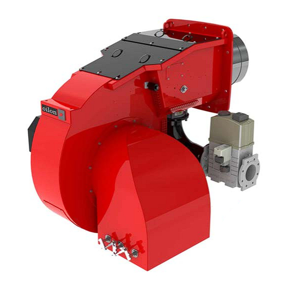
- Page 1 M4263 2206EN 14 February 2022 Operation and maintenance manual Burner models: GP-1000 M - 1200 M Burner equipment: WDx00, ME comb. head, FGR Read these instructions carefully before installation, use, or maintenance...
-
Page 3: Table Of Contents
Contents Introduction Liability disclaimer..................3 Safety precautions..................3 Product overview..................7 Flue gas recirculation (optional)..............9 Handling and storing.................10 Technical data Burner technical data................11 Other technical data and requirements............ 12 Burner control technical data..............13 Display and operating unit technical data..........15 Servomotor technical data................ 15 module technical data (WD200)............15 Oxygen sensor technical data (WD200)...........16 Flame detector technical data.............. - Page 4 4.14 Manual start-up and program stop in pre-purge position......50 4.15 Ignition position..................51 4.16 Setting ratio curve..................52 4.17 Activating FGR..................57 4.18 Setting FGR curve points................. 57 4.19 Measuring FGR..................59 4.20 Capacity range..................60 4.21 min. value control (WD200)..............60 4.22 Setting O trim control (WD200)...............62...
-
Page 5: Introduction
Oilon is unable to accept any liability for damage in case of: ● failure to follow these instructions ● other use than what is explained in this manual ●... - Page 6 Keep these instructions as well as the electrical diagrams available near the device. Oilon products are manufactured in accordance with general product standards and directives as well as based on our best knowledge of product design and different technologies. Operational safety is one of the leading principles in our product development.
- Page 7 Cut off power supply to the burner and close the manual shut-off valves always before any maintenance work. Cutting power is adequate when just inspecting the device. Secure all safety covers, enclosures, and guards with all screws before start-up. Use appropriate tools. Wear proper hearing protection and personal protective equipment, such as protective footwear, gloves, and safety goggles when necessary.
- Page 8 Take care of the boiler room Never light a fire in the boiler room. Do not store any inflammable materials in boiler room. Keep the boiler hatch closed while starting the burner and during burner operation. ● Maintain tidiness in boiler room, and keep boiler room door closed. ●...
-
Page 9: Product Overview
The manufacturing time is found in the type plate. The product's expected lifespan is at least 15 years, if it and its components are used and maintained properly. For more information on products, visit our website at www.oilon.com. M4263 2206EN... - Page 10 Label element 7: Combustion head length (additional code) -, C1, C2, C3 Combustion head length C only in use in LN80 burners. Type plate The following illustration shows an example of the type plate of Oilon burners: 8 (102) M4263 2206EN...
-
Page 11: Flue Gas Recirculation (Optional)
Type plate US ver. 2 Pos. Description Pos. Description Burner type: Oil pump supply voltage, input power and KP = Light fuel oil current, V / Phase / Hz / hp / A RP = Heavy fuel oil Degree of protection GP = Gas Serial number GKP = Light fuel oil and gas... -
Page 12: Handling And Storing
1.5 Handling and storing Storing and recycling Store device and its equipment in a dry and airy place. Protect device from dust and humidity. Follow storing and transporting instructions included in the package. Documentation is part of the product, and it must be passed on together with device, also with a second hand product. -
Page 13: Technical Data
This manual may include additional information about other burner types. However, the manual is valid only for the burner, mentioned on the front page and in the burner data table. Following information applies to standard deliveries. Burner GP-1000 M GP-1200 M Capacity, MMBtu/h 6.8–42.0 8.3–50.4... -
Page 14: Other Technical Data And Requirements
GP-1000 M - 1200 M (US) ver. 2 Tested in laboratory conditions (ambient temperature 68 °F). 2.2 Other technical data and requirements Fuel, gas use Natural gas When using other gases than natural gas, the composition of the gas must be known. Consult burner manufacturer on the suitability of the burner for special gases. -
Page 15: Burner Control Technical Data
For reducing noise level, contact the manufacturer or consult the Oilon Selection Tool (available for download on the Oilon website). Degree of protection NEMA 1 Ambient temperature range 32...+ 122 °F 2.3 Burner control technical data Burner control LMV5... Mains voltage... - Page 16 Block diagram of contact links Block diagram ver. 7 14 (102) M4263 2206EN...
-
Page 17: Display And Operating Unit Technical Data
Inputs / outputs (VSD) Connection diagram ver. 3 2.4 Display and operating unit technical data Display and operating unit AZL... Supply voltage 24 VDC –15/+10 % Power consumption < 5 W Protection degree NEMA 3 Permissible operation ambient temperature -4...+140 °F Protect the equipment from condensation, ice, and water ingress. -
Page 18: Oxygen Sensor Technical Data (Wd200)
module PLL52... Analog inlet, oxygen sensor QGO20.000D27 Analog inlet, combustion temperature Pt1000 / LG-Ni 1000 Analog inlet, flue gas temperature Pt1000 / LG-Ni 1000 Analog inlet, bus interface Protection degree NEMA 3 Permissible ambient temperature -4..+140 °F Protect the equipment from condensation, ice, and water ingress. 2.7 Oxygen sensor technical data (WD200) Oxygen sensor QGO20... - Page 19 Auxiliary detector cable max. length 328 ft Protection degree NEMA 3 Permissible operation ambient temperature -4...+140 °F ● integrated signal amplifier ● continuous or interrupted use ● mains frequency filtering ● does not detect electric arc used for ignition ● spectral sensitivity range ~1–3 μm ●...
-
Page 20: Installation
3 Installation 3.1 Space requirements Leave enough space on each side of the burner for installation, commissioning, and maintenance purposes. The minimum space requirements are presented in the following. Installation, commissioning, or service of the appliance is to be carried out by authorized and trained personnel only, adhering to all local regulations and requirements. -
Page 21: Detaching And Fastening Protective Covers
Oilon burners are attached to and supported on a transportation base. The base can be lifted from all sides with a forklift. When lifting the package, the center of gravity must be in the middle between the forks to avoid falling. - Page 22 Fastening protective covers 1. Make sure that the fixing screws are raised enough, approx. 0.79 inches. 2. Set backcover's "keyholes" through the screw heads. 3. Hold the cover slightly raised and slide it into position. Be careful not to damage the gasket.
-
Page 23: Mounting Burner Support
3.4 Mounting burner support A017211 support ver. 3 Burner support may be needed in circumstances, where burner is exposed to extraordinary stress or vibration. 1. Check that the support length is appropriate. 2. Drill 6 pcs of M8 threads to the burner's frame beam according to the support's holes. - Page 24 Burner dimensions (GP) d063634 ver. 1 Measurements (inch) Burner ØD1 GP-1000 M 62.99 17.09 11.93 39.37 57.87 43.31 20.08 23.03 35.63 34.65 29.53 19.53 GP-1200 M 62.99 17.09 11.93 39.37 57.87 43.31 20.08 23.03 35.63 36.61 29.53 20.47 Gas inlet...
-
Page 25: Combustion Head And Masonry Dimensions
3.6 Combustion head and masonry dimensions Combustion head mounting dimensions D063900 ver. 2 Masonry 1 ver. 3 Pos. Item Pos. Item Gasket, thickness 0.3 inch Ceramic wool or equivalent Mounting panel Masonry Burner øD1 α 1000 M 19.53 17.09 60–90° 1200 M 20.47 17.09... -
Page 26: Rotating Air Cone
3.7 Rotating air cone D026630 ver. 2 Pos. Item Air cone Air cone mounting screws Hole for lifting eyelet M10 (short thread) If the air intake is too close to floor level, the air cone can be rotated towards the boiler. It is also possible to adjust the noise level by rotating the air cone. -
Page 27: Installing Burner To Gas Supply Line
3.9 Installing burner to gas supply line Supply line If necessary, decrease the supply gas pressure with pressure regulating assembly. The gas supply line after the pressure regulator must be of the same size or one size larger than the valve train size. As standard, the gas connection to the burner is from the right side. -
Page 28: Installing Gas Pressure Regulating Assembly
Installing gas valve and gas pipe support Install support if gas valve size is 2.5" or larger. B-349T ver. 1 Place the supports under the gas pipe (1) and gas valves (2) as depicted in the illustration. 3.10 Installing gas pressure regulating assembly Adhere to the values given by the equipment manufacturer. - Page 29 If the gas inlet pressure is not stable, stabilize the pressure with the pressure regulator. Example of gas pressure regulating assembly B311Z ver. 4 Pos. Item Pos. Item Gas pressure regulating assembly Bellows compensator/gas hose Ball valve Safety shut-off valve, if not incl. in press. regulator Gas filter Safety relief valve, if not incl.
-
Page 30: Installing Fgr Duct System
3.11 Installing FGR duct system FGR duct system FGR Installation_monoblock ver. 3 Pos. Item Pos. Item Control damper Temperature sensor Combustion air fan FGR duct Combustion air throttle valve Condensate drain valve Combustion air In monoblock burner constructions, pos. 2 and 3 are integrated parts of the burner. Designing FGR piping When designing the piping, consider the special circumstances of FGR operation. - Page 31 ● Use carbon or stainless steel for FGR piping. Pipe wall must not be too thick. ● Route the duct with a minimum number of elbows, still allowing a normal expansion and contraction of the duct. Place pipe supports to avoid excessive load to pipe connection.
-
Page 32: Electrical Connections
3.12 Electrical connections Electrical installation may be carried out by authorized and trained personnel only. Connect the burner according to the electrical diagrams delivered with burner. Follow general and local standards and regulations as well as requirements set for electrical connections for electrical equipment. -
Page 33: Commissioning
4 Commissioning 4.1 First start-up Secure all safety covers, enclosures, and guards with all screws before start-up. Use appropriate tools. If burner start-up fails consecutively three times, do not restart burner before carefully investigating the reason for the failure. After the first start-up check the cleanliness of the gas filter weekly and replace if necessary. - Page 34 ● gas inlet pressure is correct ● equipment is installed correctly and is in working condition ● chimney is properly connected, unobstructed and flue gas damper is open To start the burner: 1. Open the fuel shut-off valves. 2. Switch on power supply. 3.
-
Page 35: Adjusting Combustion Head (Gp)
2. Replace the secondary gas nozzles [X] and [Y] with new nozzles (in the cardboard box). Test the burner. 3. Add adjusting bands and test the burner. You must order the adjusting bands separately from Oilon. 4.3 Adjusting combustion differential air pressure switch Combustion differential air pressure switch The combustion differential air pressure switch monitors pressure difference generated by burner fan. - Page 36 Higher pressure Lower pressure Electrical connections Setup switch 1 and 2 Cross head screw LGW A2 ver. 2 If pressure difference does not rise above switch setting value, burner shuts down. Differential air pressure switch should be set to trigger before CO-concentration of combustion product exceeds 1 vol%, 10 000 ppm.
-
Page 37: Adjusting Gas Pressure Switch
4.4 Adjusting gas pressure switch Gas pressure switch, max. 1 Adjusting scale 2 Reset, gas pressure switch, max. 3 Pressure measuring connection A416M ver. 3 Gas pressure switch max. should cause a permanent interlocking if burner capacity increases to be more than 1.15 times the nominal value, or if the pressure exceeds more than 1.3 times the nominal pressure. -
Page 38: Setting Gas Pressure Regulator Skp
The operating area of the gas pressure regulator is determined by the spring installed inside the pressure regulator. Spring operating area is described in the table below. Springs can be ordered from Oilon Webshop. SKP ver. 1 To change spring:... -
Page 39: Setting Gas Pressure Regulator Frs
1. Remove the plug. 2. Remove the slot-head screw by turning counter-clockwise with a chisel-point screwdriver. 3. Replace the spring. Assemble in reverse order. Do not overtighten the component’s screws. The component may become damaged. Spring type pG ("W.C.) ∆p / Color Model AGA29... - Page 40 Springs can be ordered from Oilon Webshop. Setting pressure regulator at minimum load 1. Start burner at minimum load. At minimum load throttle valve setting is 5°-10°. 2. Adjust combustion to safe level using flue gas analysis. Measure pressure regulator outlet pressure from gas valve measuring point.
- Page 41 To replace setting spring 219598b ver. 1 1. Remove protective cap A. Release spring by turning adjustment spindle B counterclockwise. Turn spindle to stop. 2. Unscrew complete adjustment spindle B and remove spring C. 3. Insert new spring D. 4. Assemble complete adjustment spindle and adjust desired offset. 5.
-
Page 42: Measuring Gas Pressure
Setpoint Color Nominal width Rp/DN spring range ("W.C) Rp 1 1/2, Rp 2, DN Rp 2 1/2, DN 100 DN 125 DN 150 DN40 DN65, 80 Spring 1 1.0–3.6 brown 229 851 229 874 229 883 229 892 229 901 229 909 Spring 2... - Page 43 Measuring nozzle pressure D048665 ver. 2 1. Nozzle pressure at nominal capacity Burner Test point 1 ("W.C.) 1000 M 29.7 1200 M 29.7 Check the tables below for adjusted pressure values. Measuring inlet and adjusted pressure M4263 2206EN 41 (102)
- Page 44 Main gas train + pilot gas train d073474 ver. 2 A. Gas inlet 4. Measuring point 2. Inlet pressure 5. Inlet pressure (pilot) 3. Adjusted pressure 6. Adjusted pressure (pilot) Burner Test point 2 Test point 3 ("W.C.) ("W.C.) 1000 M - 1200 M max.
-
Page 45: Operating And Display Unit Menu
4.8 Operating and display unit menu Menu structure Menus are divided into two user levels. First user level is User, and it does not require password. Second user level is Service. It is a password protected level for commissioning and maintenance personnel. - Page 46 StartCounter Displaying the start counter readings GasStartCount Number of startups gas, start counter (selectable) OilStartCount Number of startups oil, start counter (selectable) TotalStartCountR Total number of startups, start counter (can be reset) TotalStartCount Total number of startups, start counter (read only) Fuel Meter ...
- Page 47 Description ManualOperation SetLoad Target load setting manually, percent of maximum load (%) Autom/Manual/Off Select manual or automatic operation Auto Burner capacity adjusts automatically controlled by capacity controller according to boiler temperature or pressure ...
-
Page 48: Adjusting Operating And Display Unit Settings
VSD Module ● Configuration ● Process Data ● ProductID ● SW Version 4.9 Adjusting operating and display unit settings Scrolling menus For scrolling and changing set values of the operating and display unit menu, use the four buttons on the panel. AZL buttons ver. -
Page 49: Frequency Converter (Wd200)
4.10 Frequency converter (WD200) Frequency converter is started and stopped using potential-free release contact in burner control. Frequency converter alarm is connected to burner control with 12…24 VDC voltage signal that causes burner safety stop. Frequency converter is controlled with 0 / 4…20 mA signal. Frequency converter operation must be linear. -
Page 50: Frequency Converter Settings And Standardization (Wd200)
4.12 Frequency converter settings and standardization (WD200) Standardize the rotation speed after setting the frequency converter parameters. Turn the control selection switch S1 to position 1. The control voltage is switched on to burner control. Settings are in the following menu level: Params. - Page 51 When control voltage is switched on, and oxygen sensor is activated, heating is on and oxygen sensor is ready for operation. Activate oxygen sensor during first start-up, and always after power failure, to start heating. Oxygen sensor is ready for operation when 1292 °F is reached. It takes approx.
-
Page 52: Manual Start-Up And Program Stop In Pre-Purge Position
4.14 Manual start-up and program stop in pre-purge position Program stop With burner control ProgramStop parameter burner start-up can be stopped in selected program phase, and servomotor position can be adjusted. Pre-purge position phase 24–34 Ignition position phase 36 Transition 1 phase 44 Transition 2 phase 52... -
Page 53: Ignition Position
Gas use Primary safety control Prepurge: four air changes in max. 90 s. (Burners not exceeding 2,500 MBtu/h) Prepurge: 30 s at maximum air damper opening (high fire). If a curve point setting for full load is changed, adapt the changes to the pre-purge position settings. -
Page 54: Setting Ratio Curve
Params & Display RatioControl GasSettings Special Positions IgnitionPos IgnitionPos- Gas IgnitionPos- Air ... - Page 55 Curve point 1 ver. 4 Press Enter to scroll through stored curve points. Curve point 2 ver. 4 The pointer is positioned at the colon below the text Point. The running number of the stored curve point is shown after the colon. Curve points are stored according to capacity from smallest to biggest.
- Page 56 Curve point 4 ver. 4 When the servomotors drive to position for a set curve point, the display shows “>” instead of “:”. When the servomotors have reached their positions, “:” returns to the display. Servomotor settings can be modified only when each servomotor has reached its position.
- Page 57 ● burner minimum load, note ratio ● set fan rotation speed as small as possible, but not under 60% ● check combustion values with flue gas analysis ● check the combustion flame ● set load value and point load is determined according to current fuel consumption as a percentage of maximum load In the settings for air servomotors and frequency converter control, residual oxygen is adjusted as desired for each curve point.
- Page 58 Larger gas amount flow is reached when gas regulator valve angle is 62%. If gas consumption is not sufficient, check gas supply line control pressure and adjust if necessary. Adjust at full load curve point: ● burner capacity, note ratio ●...
-
Page 59: Activating Fgr
After commissioning the burner, check air pressure switch settings. See section Adjusting combustion differential air pressure switch. 4.17 Activating FGR Burners equipped with FGR can also be used without FGR. Whenever you activate and deactivate FGR, you will need to recheck fuel–air ratio curves. - Page 60 Time period value can be changed from: Params. & Display↵ Flue gas recirc. ↵ DelaytimeFGR Gas↵ To create curve points: 1. Go to Params. & Display↵ Ratio control ↵ Gas settings ↵ Curve Param ↵ 2. Select the required curve point and press ↵. 3.
-
Page 61: Measuring Fgr
4.19 Measuring FGR Pos. Item FGR duct FGR control valve Measuring point of residual oxygen in flue gas FGR principle monoblock ver. 3 Recirculated flue gas amount is typically 5–20 % of the flue gas/combustion air mixture amount, depending on the application. Flue gas percentage is counted as follows: FGR % = Flue gas amount recirculated ppm / (Flue gas amount recirculated ppm + combustion air amount in ppm) % To define flue gas percentage... -
Page 62: Capacity Range
FGR may cause unstable combustion. To avoid noise, vibration or other disturbance, the settings must always be defined for each burner separately. 4.20 Capacity range Burner capacity range can be set as required at service level. The minimum capacity can be larger than the first curve point, and the maximum capacity can be below the last curve point. - Page 63 min. value control When setting for the first time O2 monitor should be deactivated with man deact. Params. & Display O2Contr/Guard FuelSettings OptgMode man deact Set O min.
-
Page 64: Setting O Trim Control (Wd200)
Measuring O min. values by reducing air 1. Select desired point from previous menu level by pressing the Select -/+ buttons during burner operation. Press Enter. 2. Select third line P-Air Man by pressing the Select -/+ buttons, and press Enter. The display changes as follows: Point27 ver. - Page 65 Point2 ver. 4 3. The display changes. The second line O2ratioCon shows current residual oxygen level. Wait until the level stabilizes, and corresponds with ratio curve level. The burner control uses this level when calculating O trim control settings. Confirm the selection by pressing Enter. Point22 ver.
-
Page 66: Trim Control Operating Mode (Wd200)
Point25 ver. 4 4.23 O trim control operating mode (WD200) Select the suitable O trim control operating mode as follows: Params. & Display O2Contr/Guard FuelSettings OptgMode ... -
Page 67: O 2 Trim Control Load Limitation (Wd200)
4.24 O trim control load limitation (WD200) Select O2CtrlThreshold from the operating and display unit menu as follows: Params. & Display O2Contr/Guard Fuel settings O2CtrlThreshold Apadt.Point small Type of Fuel Fuel user def If load drops below this limit, the burner operates along parameterized ratio curves without O trim control. -
Page 68: Setting Load Controller Parameters
Description Operation BoilerSetpoint SetpointW1 Internal setpoint W1, °F Internal setpoint W1, 2. Start the burner manually by setting the Autom/Manual/Off option to Autom. The preset value from burner control is IntLC. ManualOperation ... - Page 69 Params. & Display Load- Controller Controller- Param ContrlParam- List Standard- Param Adaption ...
- Page 70 Parameter adaptation During adaptation, the burner control calculates PID parameters for process which is controlled based on the characteristics. Params. & Display LoadController Adaption StartAdaption AdaptionLoad The burner and boiler must be ready for 10 min. run, where boiler temperature or pressure is dropped to 5 % below set value, and then run with full load.
- Page 71 Operation O2Ctrl activate deactivated activated Select StartAdaption. Parameter evaluation Load control does not cause variation in boiler temperature or pressure with optimum PID parameters. When changing the setting, boiler temperature or pressure should stabilize without going up and down.
-
Page 72: Capacity Controller On/Off
If load control is not completely stabilized, but fluctuates continuously near the setpoint value, the following parameters can be used to control this. Always make sure that the PID parameters are correctly set before using the following parameters. A noticeable fluctuation of load near the set value indicates poor setting of PID parameters. -
Page 73: Boiler Temperature Limiting With Burner Control
Operation phase ver. 3 4.29 Boiler temperature limiting with burner control Boiler temperature can be limited with burner control. It can be implemented with the same sensor used for temperature control, or with a separate sensor. When pressure control is selected, temperature limiter is not in use. If limiter temperature switch-on point is reached, burner shuts down. - Page 74 1. If the set value does not reach the set step within the maximum time, the load will be increased by one stage step. 2. If the set value has reached the set step before the maximum time has elapsed, the load increases by one stage step.
-
Page 75: Measuring Flue Gas And Combustion Air Temperature (Wd200)
4.31 Measuring flue gas and combustion air temperature (WD200) Flue gas and combustion air temperature measuring sensor can be connected to O module. Select the sensor type and set the alarm threshold from the menu as follows: Params. -
Page 76: Operation
5 Operation 5.1 WiseDrive system WiseDrive 100 / 200 WiseDrive system components 1. Boiler pressure/ temperature measurement 2. Safety devices 3. O2 sensor (WD200) 4. O2 module (WD200) 5. CAN BUS 6. Control unit 7. CAN BUS 8. Gas damper 9. - Page 77 The system includes an operating and display unit for local use. A remote PC application can be used during commissioning and servicing. To enable continuous operation, the WiseDrive system uses components designed specifically for this system. The system supervises components related to safety functions with continuous self-testing.
- Page 78 Combustion air Combustion air provides the needed air pressure and volume for efficient combustion. In the WD200 system, the fan motor can be fitted with a variable speed drive. The variable speed drive adjusts air pressure according to burner’s capacity by controlling the fan speed.
-
Page 79: Legend To Pi Diagrams
Oxygen sensor (WD200) Oxygen sensor measures the amount of residual oxygen from flue gas. The sensor is a ceramic zirconium dioxide cell and self-testing. QG020 ver. 3 Flame detector QRI is a flame detector for use with gas, oil and other flames that emit infrared light. Flame signal intensity can be monitored on display. -
Page 80: Legend To Time Sequence Diagrams
Compound regulator Pressure switch, low Air dampers Pressure switch, high Butterfly valve Gauging position switch Oil pump Pressure indicator Oil pressure regulator Motor Flame arrester Ball valve Pneumatic shut-off valve Solenoid valve Safety valve One way valve Pressure regulator Adjustable valve Mesh Valve open softener Orifice... - Page 81 Times: Post-purge lockout position Post-purge time 3 gas / oil (tn3) Max. time safety phase Valve proving evacuate time Min. time home run Valve proving time atmospheric pressure Min. time start release Valve proving filling time Fan running time Valve proving time gas pressure Pre-purge time part 1 tmn1 Min.
- Page 82 Signal ON Signal OFF Next phase Stop, up to phase maximum time → 01 Stop, up to phase maximum time → 10 0...3 s 00, repetition = 0 0...30 s 01 12, repetition > 0 0...3 s Output OFF / input Irrelevant Output ON / input ON Permissible positioning range In Standby: actuator can move within the permissible positioning range, but is always driven...
-
Page 83: Burner Operation And Pi Diagram, Gas
Param.: Only LMV50... and LMV52...: Extraneous light, pilot phase, operating phase gas/oil → Separate flame supervision possible Param.: Depending on parameter StartPoint Op Param.: Depending on parameter DriveLowfire Gas or DriveLowfire Oil Param.: Depending on parameter HeavyOilDirStart Param.: Air pressure test = deactivated in standby → irrelevant in phase 10 and 12 Param.: Long post-purge time tn3 (PostpurgeT3long) Param.:... - Page 84 Burner operation During burner operation, the control unit adjusts servomotors according to capacity controller inputs. Servomotors adjust the gas regulator valve and air dampers between partial load and full load according to the capacity demand. Burner shutdown If the current partial load exceeds the capacity demand, the burner shuts down and the double solenoid valve closes.
-
Page 85: Time Sequence Diagram, Gas Use
5.5 Time sequence diagram, gas use 7550f57e/0515, Gp1 ver. 6 M4263 2206EN 83 (102) -
Page 86: Burner Automation Description, Gas Use
7550f60e/0515, Gp2 ver. 2 5.6 Burner automation description, gas use Items marked with an asterisk (*) apply only if the burner is equipped with an ignition gas valve. Prerequisites for start ● All failures and interlocks reset. ● Burner flange limit switch closed. ●... - Page 87 ● Remote control contacts closed. ● Boiler thermostat/pressure switch contact closed. ● Differential air pressure switch contact open. 20, 21 Start-up ● Burner control safety functions are activated. ● Gas safety valve (optional) opens. ● Gas pressure recognition, pressure switch min. closed. ●...
- Page 88 52* Interval 2, second safety time ends. ● Ignition gas valve closes.* ● The main flame must have been ignited by now. Otherwise, burner control does not receive a flame signal and goes to a lockout.* ● Main flame burns at a set ignition load.* 54 Servomotors run to min.
-
Page 89: Gas Valve Proving
00 Lockout phase ● Servomotors run to stand-by position. ● Burner failure activates. ● Requires manual reset. 5.7 Gas valve proving The system performs gas valve proving using a pressure switch or transmitter that monitors the section of pipe between the valves. During gas valve proving, burner control opens and closes gas valves at programmed intervals. -
Page 90: Maintenance
6 Maintenance 6.1 Burner maintenance Installation, commissioning, or service of the appliance is to be carried out by authorized and trained personnel only, adhering to all local regulations and requirements. Secure all safety covers, enclosures, and guards with all screws before start-up. -
Page 91: Dismounting Combustion Head (Gp)
● When ordering spare parts, give the burner type and serial number indicated on the burner type label or manufacturing card. If you need help with maintenance issues, contact your nearest representative or Oilon customer service at http://www.oilon.com/customer-service/. Burner contains electric and electronic components. Adhere to rules and regulations from local authorities when disposing. -
Page 92: Dismounting And Changing Burner Motor
Pos. Item Pos. Item Ignition electrode Gas nozzle fixing screw Ignition cable Gas pressure switch impulse tube Combustion head fixing screw Combustion head adjusting rod Ignition electrode combination Combustion head regulating axle Ignition electrode combination fixing screw Combustion head regulating axle fixing screw Regulating pipe locking ring Adjustment ring Support pipe fixing screw... -
Page 93: Dismounting And Changing Servomotors
If necessary, lift the fan motor with a lifting device or strap. To dismount motor and fan wheel: 1. Switch off the burner from the mains. 2. Disconnect the electrical cable of the motor. 3. If in use, detach the rotation speed sensor from the motor’s fan casing. 4. - Page 94 Servomotor of gas butterfly valve VKF-10 d074074 ver. 1 Pos. Description Pos. Description Servomotor Butterfly valve VKF-10 Servomotor fixing screw Aligning surface of servomotor’s shaft Shaft coupling Flange gasket Shaft coupling aligning plate and Cable fitting clamping screw 1. Run the servomotor to 90° position so that the clamping screw on the servomotor shaft turns horizontally.
-
Page 95: Assigning Servomotors
6.5 Assigning servomotors Addressing servomotor 1. Open servomotor protecting cover fixing screws, and remove cover. 2. Check that terminating resistor is connected as in the original servomotor. 3. Check the state of green signal light. If light is steady, servomotor is unaddressed and is ready for addressing. -
Page 96: Testing Safety And Control Devices
Param. & Display RatioControl Fuel settings Special settings Initial stage Initialstage Gas ... - Page 97 Test method Outcome Boiler pre-purging begins. The burner Step 1 1. Disconnect the high pressure hose (+) from the switch. must shut down before the pre-purge 2. Start the burner. cycle is completed. After testing, reconnect the high pressure hose. Error code 28 and a text Air pressure off appear on the display.
- Page 98 Gas shut-off valves If the burner is equipped with an automatic valve proving system the valves are tested to be leak free during each start-up sequence. To prove the valves manually: 1. Install a pressure gauge between the fuel shut-off valves. Refer to the valve manufacturer’s instructions for the exact location of the measuring port.
-
Page 99: Troubleshooting
6.7 Troubleshooting Before troubleshooting, check the section First start-up If the fault can not be found in the First start-up, check the individual burner functions. Reset the burner control if it is in lockout position. The burner goes to standby position. When the prerequisites for start are fulfilled, the burner starts. - Page 100 Condition Possible cause Action Faulty motor contactor. Change. Faulty motor. Change. Fault in frequency converter or Check error and reset. soft starter (if equipped). Lack of fan air pressure Condition Possible cause Action Fan motor starts, but during pre- Faulty differential air pressure Check setting, adjust if necessary.
- Page 101 Condition Possible cause Action Faulty fuel/air ratio. Adjust. Faulty combustion head Check and adjust. adjustment. Nozzle dirty or blocked. Clean or change. Too low ignition load. Check. Burners with ignition pilot gas valve, ignition flame does not form Condition Possible cause Action...
-
Page 102: Maintenance During Shutdown
● Check piping, valve operation, filters, and gaskets. Start operation only after a thorough inspection. Before start-up, make sure that the appliance is in good working order. If you need help with maintenance and service, contact your nearest representative or Oilon customer service. 100 (102) M4263 2206EN... -
Page 103: Burner Parts (Gp)
6.9 Burner parts (GP) d067537 - GP-1000 M - 1200 M WDx00 US ver. 1 Pilot gas train Main gas train The assembly may vary depending on the scope of delivery. M4263 2206EN 101 (102) -
Page 104: Burner Part List
6.10 Burner part list Recommended change interval Part name 1–2 3–5 on demand/ year years years start-up max. 1 Protective cover 2 Flange gasket 3 Fan motor 4 Fan wheel ... - Page 106 Contact information of Oilon dealer: OILON GROUP P.O. Box 5 FI-15801 LAHTI FINLAND Tel: +358 3 85 761 Fax: +358 3 857 6239 Email: info@oilon.com Date of installation: www.oilon.com...
Need help?
Do you have a question about the GP-1000 M and is the answer not in the manual?
Questions and answers