Table of Contents
Advertisement
OPERATING AND MAINTENANCE
INSTRUCTIONS FOR LIGHT OIL
Burners without preheating
Read these instructions carefully before installation, commissioning or maintenance of
the burner!
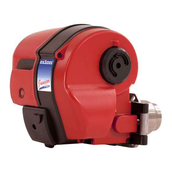
BURNERS
Junior Pro 1
J10
J18
Junior Pro 2
J20
J45
J50
Burners with preheating
Junior Pro 1
LJ10
LJ18
Junior Pro 2
LJ20
LJ45
LJ50
OILON HOME OY
P.O. Box 5, 15801 Lahti
Visiting address:
Tarmontie 4,
15860 Hollola
Tel. (03) 85 761
fax (03) 857 6239
info@oilon.com
www.oilon.com
10090943EN
Advertisement
Table of Contents


Need help?
Do you have a question about the Junior Pro 1 J10 and is the answer not in the manual?
Questions and answers