Advertisement
https://wiki.teltonika-gps.com/view/FMM920_First_Start
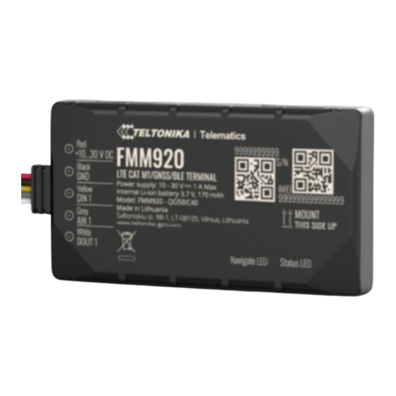
FMM920 First Start
Main Page
>
Basic Trackers
Small and smart tracker with Bluetooth and internal backup battery
Contents
1 How to insert Micro-SIM card
How to insert Micro-SIM card
1.
Gently remove FMM920 cover using plastic pry tool from both sides.
Insert Micro-SIM card as shown with PIN request disabled or read
2.
enter it later in Configurator. Make sure that Micro-SIM card cut-off corner is pointing
forward to slot.
3.
Remove the adhesive tape protection.
4.
Place the battery inside the casing of the FMM920. Make sure the adhesive tape sticks to the
casing.
5.
Connect the internal battery to the FMM920 PCB.
6.
Attach device cover back. Device is ready to be connected.
Micro-SIM card insertion/removal must be performed when device is powered off –
external voltage and internal battery disconnected. Otherwise Micro-SIM card might be
damaged or device will not detect it.
>
FMM920
> FMM920 First Start
Security info
how to
Advertisement
Table of Contents

Subscribe to Our Youtube Channel
Related Manuals for Teltonika FMM920


Summary of Contents for Teltonika FMM920
- Page 1 Configurator. Make sure that Micro-SIM card cut-off corner is pointing forward to slot. Remove the adhesive tape protection. Place the battery inside the casing of the FMM920. Make sure the adhesive tape sticks to the casing. Connect the internal battery to the FMM920 PCB.
- Page 2 DOUT 1 Digital output. Open collector output. Max. 3,3 A DC. Configuration (Windows) At first FMM920 device will have default factory settings set. These settings should be changed according to the user's needs. Main configuration can be performed via Teltonika Configurator software.
- Page 3 Various and etc. FMM920 has one user editable profile, which can be loaded and saved to the device. After any modification of configuration the changes need to be saved to device using Save to device button. Main buttons offer following functionality: Load from device –...
- Page 4 FMM920 can be mounted under the plastic panel behind the front window, with the sticker direction to a window (sky). It is recommended to place FMM920 behind dashboard as close to the window as possible. A good example of GNSS antenna placement is displayed in a picture below (area colored green).
- Page 5 Safety information This message contains information on how to operate FMM920 safely. By following these requirements and recommendations, you will avoid dangerous situations. You must read these instructions carefully and follow them strictly before operating the device! The device uses SELV limited power source. The nominal voltage is +12 V DC. The allowed voltage range is +10..+30V DC.
Need help?
Do you have a question about the FMM920 and is the answer not in the manual?
Questions and answers