Table of Contents
Advertisement
Quick Links
https://wiki.teltonika-gps.com/view/FMM130_First_Start
FMM130 First Start
Main Page
>
Advanced Trackers
Advanced CAT M1/GSM/GNSS/BLE terminal with internal antennas and backup battery
Contents
1 How to insert SIM card and connect the battery
How to insert SIM card and connect the battery
1.
Gently remove FMM130 cover using plastic pry tool from both sides.
Note: To properly open a new case please watch this video.
2.
Insert SIM card as shown with PIN request disabled or read
later in
Teltonika
slot. SIM slot 1 is closer to PCB, SIM slot 2 is the upper one.
3.
Connect battery as shown to device. Position the battery in place where it does not obstruct
other components.
After configuration, see
4.
SIM card insertion/removal must be performed when device is powered off – external
voltage and internal battery disconnected. Otherwise SIM card might be damaged or
device will not detect it.
>
FMM130
> FMM130 First Start
Configurator. Make sure that SIM card cut-off corner is pointing forward to
"PC Connection
(Windows)", attach device cover back.
Security info
how to enter it
Advertisement
Table of Contents

Related Manuals for Teltonika FMM130


Summary of Contents for Teltonika FMM130
- Page 1 5.1 Precautions How to insert SIM card and connect the battery Gently remove FMM130 cover using plastic pry tool from both sides. Note: To properly open a new case please watch this video. Insert SIM card as shown with PIN request disabled or read...
- Page 2 Battery placement after complete device disassembling Using double sided tape, stick internal battery to the bottom part of the device case. Battery should be glued approximately 15 millimeters from the bottom wall of the case. Picture on the left. Connect battery to the PCB. Gently place PCB into the bottom case.
- Page 3 Data for 1–Wire devices. INPUT 5 RX EXT (LVCAN - RX). PC Connection (Windows) Power-up FMM130 with DC voltage 10-30 V power supply using supplied power cable. LED’s should start blinking, see “FMM130 LED status”. Connect device to computer using Micro-USB cable or Bluetooth connection:...
- Page 4 Various and etc. FMM130 has one user editable profile, which can be loaded and saved to the device. After any modification of configuration the changes need to be saved to device using Save to device button. Main buttons offer following functionality: Load from device –...
- Page 5 Data Acquisition configured and – where data acquiring parameters can be configured. More details about FMM130 configuration using Configurator can be found here. Quick SMS configuration Default configuration has optimal parameters present to ensure best performance of track quality and data usage.
- Page 6 If device has made a record it is sent to the server every 120 seconds After successful SMS configuration, FMM130 device will synchronize time and update records to configured server. Time intervals and default I/O elements can be changed by using Teltonika Configurator parameters.
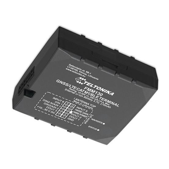
- Page 7 Installation photos FMM130 is the device that has internal GNSS and GSM antenna. Device should be mounted with the sticker / engraving view to the open sky (metal free). FMM130 area with engraving is shown in figure below: FMM130 can be mounted under the plastic panel behind the front window, with the sticker / engraving direction to a window (sky).
- Page 8 The device must be firmly fastened in a predefined location. The programming must be performed using a PC with autonomic power supply. The device is susceptible to water and humidity. Installation and/or handling during a lightning storm is prohibited. https://teltonika-gps.com/product/fmm130/...
Need help?
Do you have a question about the FMM130 and is the answer not in the manual?
Questions and answers