Table of Contents
Advertisement
Quick Links
Advertisement
Table of Contents

Related Manuals for Teltonika Telematics FMM650


Summary of Contents for Teltonika Telematics FMM650
- Page 1 FMM650 Professional tracker with CAN data reading feature Quick Manual v1.1...
-
Page 2: Table Of Contents
CONTENT Know your device ........................................3 Pinout ...........................................4 Wiring scheme ........................................5 Set up your device ......................................6 PC Connection (Windows) ....................................7 How to install USB drivers (Windows) ................................7 Configuration (Windows) ....................................8 Quick SMS configuration ....................................10 Mounting recommendations..................................12 Basic characteristics ......................................13 LED indications ......................................... -
Page 3: Know Your Device
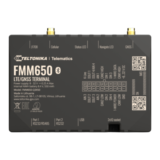
KNOW YOUR DEVICE TOP VIEW BOTTOM VIEW (WITHOUT COVER) TOP VIEW (WITHOUT COVER) J1708 STATUS NAVIGATE GNSSS ANTENNA CELLULAR ANTENNA SOCKET SOCKET RS232/RS485 BATTERY MICRO SD DUAL-SIM 2x10 RS232 MICRO-USB SOCKET SLOT SLOT SOCKET Quick Manual v1.1 // FMM650... -
Page 4: Pinout
PINOUT SAE J1939 CAN interface High PIN NUMBER PIN NAME DESCRIPTION CAN 2H channel 2 GND (-) Ground Analog input, channel 1. Input AIN1 range: 0-30V/0-10V DC SAE J1939 CAN interface Low CAN 1L channel 1 Digital output. Open collector DOUT4/ output OR Analog input, channel 1WIRE... -
Page 5: Wiring Scheme
WIRING SCHEME RS232 AIN3 K-LINE CONFIGURATION IRIDIUM EDGE DOUT1 VIA PC DOUT2 DOUT3 DOUT4/AIN4 IGNITION DETECTION BUZZER LED LIGHTS TACHOGRAPH AIN1 AIN2 CAN2L CAN2H CARRIER FREEZER DIN2 DIN1 DIN3 RELAY DIN4 1WIRE POWER 1WIRE DATA CAN1L CAN1H GARMIN ANALOG LLS SENSOR ALARM BUTTON FUEL GAUGE +8...32 V DC... -
Page 6: Set Up Your Device
Security info how to enter it later in Teltonika Configurator . Make sure that SIM card cut-off corner is pointing forward to slot. SIM slot 1 is closer to PCB, SIM slot 2 is the upper one. -
Page 7: Pc Connection (Windows)
You will need to install USB drivers, see “How to install USB drivers (Windows) ” You are now ready to use the device on your computer. wiki.teltonika-gps.com/view/FMM650_LED_status 1 Page 7, "How to install USB drivers" 2 HOW TO INSTALL USB DRIVERS (WINDOWS) -
Page 8: Configuration (Windows)
CONFIGURATION (WINDOWS) At first FMM650 device will have default factory settings set. These settings should be changed according to the users needs. Main configuration can be performed via Teltonika Configurator software. Get the latest Configurator version from here . Configurator operates on Microsoft Windows OS and uses prerequisite MS .NET Framework. - Page 9 Data Acquisition – where data acquiring parameters can be configured. More details about FMM650 configuration using Configurator can be found in our Wiki wiki.teltonika-gps.com/view/FMM650_Status_info wiki.teltonika-gps.com/view/FMM650_Status_info#GNSS_Info wiki.teltonika-gps.com/view/FMM650_Status_info#GSM_Info wiki.teltonika-gps.com/view/FMM650_Status_info#I.2FO_Info wiki.teltonika-gps.com/view/FMM650_Status_info#Maintenance wiki.teltonika-gps.com/index.php?title=FMM650_GPRS_settings After connection to Configurator Status window will be wiki.teltonika-gps.com/index.php?title=FMM650_Data_acquisition_...
-
Page 10: Quick Sms Configuration
QUICK SMS CONFIGURATION Default configuration has optimal parameters present to ensure best performance of track quality and data usage. Quickly set up your device by sending this SMS command to it: « setparam 2001:APN;2002:APN_username;2003:APN_password;2004:Domain;2005:Port;2006:0» Note: Before SMS text, two space symbols should be inserted. GPRS SETTINGS: 2001 –... - Page 11 After successful SMS configuration, FMM650 device will synchronize time and update records to configured server. Time intervals and default I/O elements can be changed by using Teltonika Configurator SMS parameters wiki.teltonika-gps.com/view/Teltonika_Configurator wiki.teltonika-gps.com/view/Template:FMC_Device_Family_Parameter_list Quick Manual v1.1 // FMM650...
-
Page 12: Mounting Recommendations
MOUNTING RECOMMENDATIONS CONNECTING WIRES • Wires should be fastened to the other wires or non-moving parts. Try to avoid heat emitting and moving objects near the wires. • The connections should not be seen very clearly. If factory isolation was removed while connecting wires, it should be applied again. -
Page 13: Basic Characteristics
LED INDICATIONS BASIC CHARACTERISTICS MODULE NAVIGATION LED INDICATIONS Name FMM650-Q3X50: Quectel BG95-M3 BEHAVIOUR MEANING Technology LTE CAT M1/NB-IoT/GSM Permanently GNSS GNSS signal is not received switched on Module Name Airoha AG3335MB Blinking every Normal mode, GNSS is working second GPS, GLONASS, GALILEO, BEIDOU, GNSS QZSS GNSS is turned off because:... - Page 14 Data support SMS (text/data) Analog Inputs Class 4 for GSM850/900: 23±2dBm 1-Wire temperature Class 1 for GSM1800/1900: sensors Transmit power 20±2dBm Class 3 for LTE-TDD: 23±2.7dBm 1-Wire iButton Class 3 for LTE-FDD: 23±2.7dBm RS232 POWER RS485 8 - 32 V DC with overvoltage CAN J1939 Input voltage range (compatible with pulse 5a and pulse...
- Page 15 Online Deep Sleep, -40 °C to +85 °C Sleep modes (without battery) Deep Sleep Battery Charging FOTA Web FOTA Teltonika Ta = 20 ± 5 °C (Ambient Temp.) temperature Configuration and Configurator (USB, Bluetooth), firmware update FMBT mobile application Battery Discharge (Configuration) Ta = 20 ±...
-
Page 16: Electrical Characteristics
ELECTRICAL VALUE CHARACTERISTIC DESCRIPTION CHARACTERISTICS MIN. TYP. MAX. UNIT Input resistance (DIN4) kΩ Input voltage Supply VALUE (Recommended CHARACTERISTIC voltage Operating Conditions) DESCRIPTION MIN. TYP. MAX. UNIT Input Voltage threshold (DIN1, DIN2, DIN3, SUPPLY VOLTAGE DIN4) Supply Voltage (Recommended ANALOG INPUT Operating Conditions) Input Voltage (Recommended... - Page 17 VALUE CHARACTERISTIC DESCRIPTION MIN. TYP. MAX. UNIT Short circuit current (UOUT> 0 V) CAN INTERFACE Internal terminal Ω resistors CAN bus Differential input kΩ resistance Recessive output voltage Differential output voltage Common mode input voltage Quick Manual v1.1 // FMM650...
-
Page 18: Safety Information
SAFETY INFORMATION Do not disassemble the device. If the device is damaged, the power supply cables are not isolated or the isolation is damaged, DO NOT touch the device before unplugging the power supply. This message contains information on how to operate All wireless data transferring devices produce FMM650 safely. -
Page 19: Certification And Approvals
User‘s Manual before your start using the electronic and electric equipment should not be device. Full User‘s Manual version can be found in mixed with general household waste. Wiki 1 wiki.teltonika-gps.com/index.php?title=FMM650 CHECK ALL CERTIFICATES All newest certificates may be found in our Wiki wiki.teltonika-gps.com/view/FMM650_Certification_%26_Approvals... -
Page 20: Warranty
Warranty does not apply to any consequential damages. • Warranty is not applicable for supplementary product equipment (i. e. PSU, power cables, antennas) unless the accessory is defective on arrival. • More information on what is RMA wiki.teltonika-gps.com/view/RMA_guidelines Quick Manual v1.1 // FMM650...
Need help?
Do you have a question about the Telematics FMM650 and is the answer not in the manual?
Questions and answers