
Related Manuals for Struers Discotom-100


Summary of Contents for Struers Discotom-100
- Page 1 Discotom-100 Instruction Manual Original Instructions Doc. no.: 16157025-03_A_en Date of release: 2023.09.05...
- Page 2 Copyright The contents of this manual are the property of Struers ApS. Reproduction of any part of this manual without the written permission of Struers ApS is not allowed. All rights reserved. © Struers ApS. Discotom-100...
-
Page 3: Table Of Contents
Table of Contents 1 About this manual 1.1 Accessories and consumables 2 Safety 2.1 Intended use 2.2 Discotom-100 safety precautions 2.2.1 Read carefully before use 2.3 Safety messages 2.4 Safety messages in this manual 3 Get started 3.1 Device description 3.2 Overview 3.3 Dimensions... - Page 4 7.2.5 Clean the flushing gun nozzle 7.3 Weekly 7.3.1 The machine 7.3.2 Cutting chamber 7.3.3 Recirculation unit 7.4 Monthly 7.4.1 Cooling fluid 7.4.2 Lubricate the cutting table 7.4.3 Clamping devices 7.5 Annually 7.5.1 Test the safety devices 7.6 Cutting table 7.7 Cut-off wheels Discotom-100...
- Page 5 11 Service and repair 11.1 Service information 12 Disposal 13 Troubleshooting 13.1 Machine problems 13.2 Cutting problems 13.3 Error messages 14 Technical data 14.1 Technical data 14.2 Cutting capacity 14.3 Diagrams 14.4 Legal and regulatory information 15 Manufacturer Declaration of Conformity Discotom-100...
-
Page 6: About This Manual
The Struers Website (http://www.struers.com) Consumables The equipment is designed to be used only with Struers consumables specifically designed for this purpose and this type of machine. Other products may contain aggressive solvents, which dissolve e.g. rubber seals. The warranty may not cover damaged machine parts (e.g. -
Page 7: Discotom-100 Safety Precautions
Instructions for Use and, where applicable, Safety Data Sheets for the applied consumables. For maximum safety and lifetime of the machine, use only original Struers consumables. Use only intact cut-off wheels. The cut-off wheels must be approved for use with rotational speeds between 1,500 and 3,000 rpm. -
Page 8: Safety Messages
30. Prior to any service, disconnect the machine and wait for 10 minutes until the residual potential on the inverter capacitors is discharged. 31. Do not restart the Discotom-100 or cycle the electrical power supply more than once every three minutes. This may result in damage to the frequency inverter. -
Page 9: Safety Messages In This Manual
Switch off the electrical power supply before installing electrical equipment. The machine must be earthed (grounded). Make sure that the actual electrical power supply voltage corresponds to the voltage stated on the type plate of the machine. Incorrect voltage can damage the electrical circuit. Discotom-100... - Page 10 CAUTION This machine must be operated and maintained only by skilled/trained personnel. CAUTION The equipment is designed to be used only with Struers consumables specifically designed for this purpose and this type of machine. CAUTION The protective cover will minimize the risk of ejection but will not eliminate it completely.
- Page 11 Take care of your fingers when handling the machine. Wear safety shoes when handling heavy machinery. General safety precautions WARNING Struers equipment must only be used in connection with and as described in the Instruction Manual supplied with the equipment. Discotom-100...
-
Page 12: Get Started
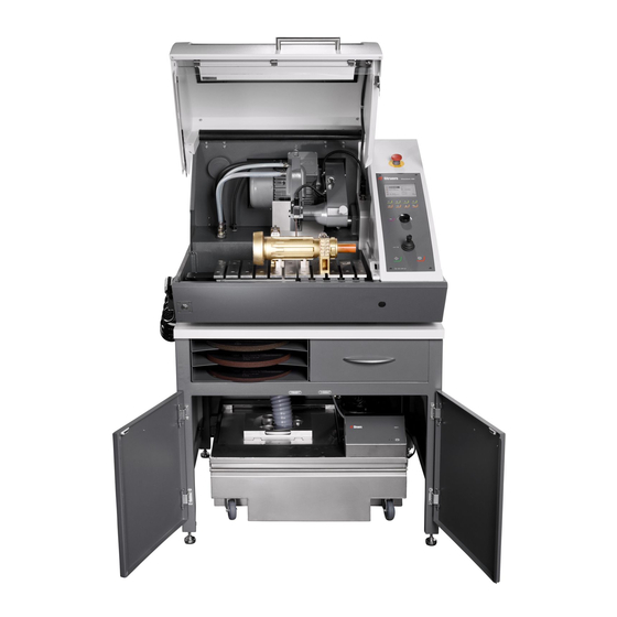
Get started Device description Discotom-100 is a manual/automatic cut-off machine with a motorized Y-table and optional X-table. The machine is designed for wet, abrasive cutting of all stable and non-explosive metals. The machine must be connected to a suitable recirculation system, which supplies cooling fluid to the workpiece and cut-off wheel during cutting. -
Page 13: Overview
Protective cover E Joystick for table movement J Safety lock release Emergency stop The emergency stop button is located on the front of the machine. – Push the red button to activate. – Turn the red button clockwise to release. Discotom-100... - Page 14 Remember to reactivate the safety lock release before operating the machine. Cutting chamber A Cut-off wheel guard B Cut-off wheel flanges C Safety lock D Y-table E X-table (optional) Note Do not use the emergency stop for operational stop of the machine during normal operation. Discotom-100...
- Page 15 D USB port for software update Cooling fluid inlet E Power supply cable connection J Flushing gun Main switch • Turn the main switch clockwise to switch on the power. Note The AUX output is turned on during the cutting process. Discotom-100...
- Page 16 3 Get started Hold-to-run button • To position the cutting table while the protective cover is open, press the hold-to-run button while you operate the joystick. Discotom-100...
-
Page 17: Dimensions
3 Get started Dimensions Side view Discotom-100... - Page 18 3 Get started Footprint Discotom-100...
-
Page 19: Control Panel Functions
Push the knob to store modified settings. Joystick • Move up-or down to position the Y-table. • Move left or right to position the X-table (optional) Flush Starts and stops the pump to flush the cutting chamber. AxioWash Starts the AxioWash function. Discotom-100... -
Page 20: Transport And Storage
• Package the unit securely before transportation. Insufficient packaging could cause damage to the unit and will void the warranty. Contact Struers Service. • We recommend that you use the original packaging and fittings. -
Page 21: Transport
Secure the cutting arm with the transportation support. Move the recirculation cooling unit. Place the lifting straps on the designated lifting points on the machine. Note The crane and the straps must be approved to at least twice the weight of the load. Discotom-100... -
Page 22: Installation
Optional accessories may be included in the packing box. The packing box contains the following items: Pcs. Description Discotom-100 Fork spanner for cut-off wheel: 24 mm Triangle key for safety lock release Connector pipe for water outlet Elbow pipe for water outlet... -
Page 23: Lift The Machine
Remember to re-activate the safety lock release before operating the machine. Weight Discotom-100 204 kg (450 lbs) Transportation support A transportation support is mounted to support the cutting arm during transport. - Page 24 Without lifting bar With lifting bar Struers recommends the use of a lifting bar to keep the straps apart below the lifting point. Lift the machine onto the table. Lift the front of the machine and carefully move into place using the rollers.
-
Page 25: Location
The machine must be placed on a safe and stable table with an adequate working height.The table must be able to carry at least the weight of the machine and the accessories. A workbench designed for Struers table top machines is available as an accessory. Discotom-100... - Page 26 Make sure that the work station has adequate lighting. Avoid direct glare (dazzling light sources within the operator's line of vision) and reflected glare (reflections of light sources). A minimum of 300 Lumen is recommended to illuminate the controls and other work areas. Discotom-100...
-
Page 27: Power Supply
Incorrect voltage can damage the electrical circuit. 5.5.1 Connection to the machine Procedure Open the electrical connection box. Connect the power cable as described below: EU cable UL cable L1: Brown L1: Black L2: Black L2: Red Discotom-100... -
Page 28: Power Supply Cable - Recommended Specifications
Max. load 3 x 200-240V 16 A 30 A 3 x 380-480V 15 A 5.5.3 External short circuit protection Note The machine must always be protected by external fuses.See the electrical table for details on the fuse size required. Discotom-100... -
Page 29: Residual Current Circuit Breaker (Rccb)
For intensive use, and for materials generating a lot of swarf, we recommend that you use a recirculation unit with band filter. To connect the machine to a recirculation cooling unit: Plug the communication cable of the cooling control unit into the machine's control socket. Discotom-100... -
Page 30: Exhaust (Optional)
We recommend the use of an exhaust system, as workpieces can emit harmful gases when cut. The exhaust system will also reduce the level of water condensation on the sides of the cover. Minimum capacity:50 m /h (1766 ft /h). To connect the machine to an exhaust system: Discotom-100... -
Page 31: Noise
For information on the total vibration exposure to hand and arm, see this section: Technical data ►91. Manual cutting of workpieces causes vibrations. Take action to lower the vibration where possible; decrease the pressure on the handle or use a vibration-reducing glove. Discotom-100... -
Page 32: Operate The Device
Operate the device Change the cut-off wheel. Note The spindle of the Discotom-100 is a left-hand thread. Note To protect the cut-off wheel and flanges, you must place conventional cut-off wheels based on Al2O3 or SiC abrasives between two cardboard washers. -
Page 33: Position The Cutting Table
Only use the flushing gun for cleaning inside the cutting chamber. CAUTION Always wear protective gloves and safety goggles when you use the flushing gun. Remove the flushing gun from the holder. Point the gun into the flushing chamber. Discotom-100... - Page 34 Always place the flushing gun back in its holder when you have finished using it. Do not use the flushing gun to clean the safety guard as this can result in water We recommend that the flushing gun is operated at a pressure of max. 3 bar. Discotom-100...
-
Page 35: Cutting Table
The display is primarily divided into 2 areas. The position of these areas and the information they contain are explained in the illustration below, which uses the Options menu as an example: Discotom-100... - Page 36 When you press a key, a short beep indicates that the command has been accepted, whereas a long beep indicates that the key cannot be activated at the moment. You can switch this sound on or off in Configuration, under Options. Discotom-100...
-
Page 37: Edit Values
(Enter) will toggle between the 2 options. Turn the knob to increase or decrease the numeric value (or to toggle between the two options). Push the knob to accept the new value. If you press Esc, the changes are reversed to the original value. Discotom-100... -
Page 38: Software Settings
Press Esc to accept the option and return to the previous menu, or turn the knob to select and edit other options in the menu. 6.4.5 Software settings When switching the machine on for the first time, the Select language screen will appear. To change the language after this, see Change the language ►40). Discotom-100... - Page 39 Select Save & Exit. The Main menu now appears in the language you have chosen. When you start the machine, it will open the last screen that was used before it was switched off. To go to the Main menu, press Esc. Discotom-100...
- Page 40 6 Operate the device Change the language Open the Configuration menu. Discotom-100...
- Page 41 6 Operate the device Open the Options menu. Open the Language pop-up menu. Discotom-100...
-
Page 42: Operation Mode
To change the operation mode: Go to the Options menu, under Configuration. Select Operation mode. Select Pass code. Use the F1 and F2 keys to select digits. Turn the knob to change the digits and push knob to enter the pass code. Discotom-100... -
Page 43: Change The Cutting Mode And Parameters
When a pass code is set, you have 5 attempts to enter the correct pass code, after which the machine will be locked. Re-start the machine using the main switch, then enter the correct pass code. 6.4.7 Change the cutting mode and parameters Cutting display The cutting display shows two types of information: Discotom-100... - Page 44 The bottom area of the display shows the motor information: – Load %: Motor load. – Temp %: Motor temperature. The values displayed are in relative (%) values. Change the cutting mode The Discotom-100 has two cutting modes: Automatic and Manual. Discotom-100...
- Page 45 To adjust the values of these parameters: Use the knob to select a cutting parameter. Turn the knob to change the value of the parameter. Push the knob to store the new value. Cut-off wheel To select or change the cut-off wheel: Discotom-100...
- Page 46 6 Operate the device Select the cut-off wheel parameter. Select a wheel category. Discotom-100...
- Page 47 The selected cut-off wheel is now displayed, and the rotational speed of the wheel is inserted. Intelligent speed adjustment To use the intelligent predefined rpm adjustment: Press F1 in the Select cut-off wheel menu to enable the intelligent adjustment. Discotom-100...
- Page 48 6 Operate the device Select a cut-off wheel to adjust the rpm. Select the Vickers hardness of the material you want to cut. The rpm setting for the cut-off wheel is changed accordingly. Discotom-100...
- Page 49 6 Operate the device Push the knob to store the value. Wheel speed To change the cut-off wheel speed: Select the speed parameter. Discotom-100...
- Page 50 6 Operate the device Use the knob to adjust the wheel speed (1500 - 3000 rpm). Cutting mode To change the cutting mode: Select the cutting mode parameter. Discotom-100...
- Page 51 Impact cutting can result in higher wheel wear, but will reduce the risk of overheating the workpiece that otherwise can take place with an inaccurate wheel / material combination. Feed speed To set the feed speed: Discotom-100...
- Page 52 6 Operate the device Select the feed speed parameter. Use the knob to adjust and accept the settings. MultiCut (Optional) To select the MultiCut mode: Discotom-100...
- Page 53 6 Operate the device Select the MultiCut parameter. Select the desired setting. Single cut Mode 1 Cut up to 10 slices of equal thickness Mode 2 Cut up to 10 slices of varying thickness Discotom-100...
- Page 54 This parameter is automatically calculated, and it displays the required movement of the x-table to cut the samples, based on the parameter settings. MultiCut 2 With the MultiCut 2 mode, you can cut up to 10 samples of different widths. Discotom-100...
- Page 55 Press F1 to clear all sample values and return the menu to its default. MultiCut 3 With the MultiCut 3 mode, you can cut up to 10 samples at different relative distances from the zero, or starting position. The distances are manually entered. To set up the distances: Discotom-100...
- Page 56 Cut at zero pos. Select this parameter to make an initial cut at zero position. Otherwise, the machine will start cutting at position 1. No of samples Sets the number of samples that will be cut. Discotom-100...
- Page 57 To set up the distances: Position the workpiece relatively close to the cut-off wheel and clamp it. Use the joystick to move the X-table to the position where the first cut is to be made. Discotom-100...
-
Page 58: Stop Modes
If the cursor is placed outside the cutting position box, F1 will clear all positions. Hint Press F2 to move the X-table until the sample is in the starter position. 6.4.8 Stop modes To select a stop mode: Select the stop mode parameter. Discotom-100... - Page 59 6 Operate the device Select the desired setting. The Discotom-100 has 3 stop modes: – Auto – Relative – Absolute Auto When Auto stop mode is selected, the machine automatically stops when the workpiece has been cut through. We recommend that you use this mode for normal cutting.
- Page 60 The Y-table is set to stop in a position relative to where cutting starts. After entering the stop position (approximate sample size + wheel wear) the cutting process will stop as soon as the specified position has been reached. The positioning range (table travel) is 0-200 mm. Discotom-100...
-
Page 61: Motor Load And Temperature Display
The Y-table is set to stop in a fixed position measured from the zero position, where the cutting table is at the very front of the cutting chamber. The positioning range is 0-200 mm. 6.4.9 Motor load and temperature display The motor load and temperature values displayed are relative percentage (%) values. Discotom-100... -
Page 62: Start The Cutting Process
Wear suitable gloves to protect fingers from abrasives and warm/sharp specimens. CAUTION Check that the protective cover is in full working condition prior to cutting. CAUTION Laser radiation. Do not stare into beam or expose users of telescopic optics. Class 2M laser product. Discotom-100... - Page 63 Press Start. The cut-off wheel starts rotating and the cooling water starts to flow. Pull the cutting handle down and let the cut-off wheel work itself into the workpiece. Increase the force and begin cutting. Reduce the force when the cut-off wheel has almost cut through the workpiece. Discotom-100...
-
Page 64: Stop The Cutting Process
You can stop the cutting process at any time during the cutting process. Note The cut-off wheel may stop rotating if the speed is set to the lowest level. Do not use this function to stop the cutting process. Press Stop to stop the cut-off wheel. Discotom-100... -
Page 65: Configuration
6 Operate the device Configuration 6.5.1 Options Select Configuration in the Main menu. Open the Options menu. Discotom-100... - Page 66 The Feed and Stop values in the display panel can be set to be displayed in either mm (default) or inches. Time Set the time to get correct readings from the log files. Date Set the date to get correct readings from the log files. Discotom-100...
-
Page 67: User Defined Cut-Off Wheels
In this case, you can specify an additional cutting distance to make sure that the workpiece is cut completely. The additional cutting distance can be specified between 0-25 mm. 6.5.2 User defined cut-off wheels To set up a new cut-off wheel: Select New in the User defined cut-off wheels menu. Discotom-100... - Page 68 6 Operate the device Insert a name for the cut-off wheel or press F4 to accept the suggestion (UCW: User defined cut-off wheels). Select the newly created cut-off wheel. Discotom-100...
-
Page 69: Reset Functions
Reduce the rotational speed. Causes increased wheel wear. or burning of the specimen? If reduced rotational speed fails to solve problem, change to a softer cut-off wheel. How can I avoid uneven cuts? Reduce the rotational speed. Causes increased wheel wear. Reduce the feed speed. Discotom-100... -
Page 70: Maintenance And Service
(SRP/CS)" in the section "Technical data" in this manual. Technical questions and spare parts If you have technical questions or when you order spare parts, state serial number and voltage/frequency. The serial number and the voltage are stated on the type plate of the machine. Discotom-100... -
Page 71: General Cleaning
Avoid skin contact with the cooling fluid additive. Note The recirculation water contains additive and grinding residue and you must not dispose of it into the waste water drain. Recirculation water must be disposed of in compliance with local safety regulations. Discotom-100... -
Page 72: Axiowash
Remove the workpiece and tools from the cutting chamber. Close the adjustable cleaning nozzles. Close the cover. Press the AxioWash key on the Control Panel. Press F1 to start cleaning. The AxioWash program will run for the preset time. Discotom-100... -
Page 73: Daily
Using the flushing gun to clean the inside of the protective cover can cause spillage of cooling fluid on the floor. When AxioWash is finished: Take the flushing gun and point it towards the bottom of the cutting chamber. Discotom-100... -
Page 74: Protective Cover
Visually inspect that the cut-off wheel guard is intact. 7.2.4 Safety lock The interlock tongue must be checked regularly for damage and perfect fitting. • Check the interlock tongue for correct function. It must slide unobstructed into the locking mechanism. Discotom-100... -
Page 75: Clean The Flushing Gun Nozzle
• Clean painted surfaces, and the control panel with a soft damp cloth and common household detergents. For heavy duty cleaning, use Struers Cleaner. • Clean the cover with a soft damp cloth and a common household anti-static window cleaning agent. -
Page 76: Monthly
We recommended that you thoroughly clean and lubricate the quick clamping device and vertical quick clamping device at regular intervals. Annually 7.5.1 Test the safety devices WARNING Do not use the machine with defective safety devices. Contact Struers Service. Discotom-100... - Page 77 Activate the emergency stop. If the machine does not stop the cutting process, press Stop and contact Struers Service. Test 2 Activate the emergency stop. Press Start. If the machine starts the cutting process, press Stop and contact Struers Service. Protective cover Test 1 Start a cutting process.
-
Page 78: Cutting Table
Open the cover. Without pressing the hold-to-run button, use the joy stick to move the cutting table and/or cutting arm. If the cutting table and/or the cutting arm move, contact Struers Service. Cutting table The stainless steel bands are available as spare parts and must be replaced if they become worn or damaged. -
Page 79: Spare Parts
If you have technical questions or when you order spare parts, state the serial number. The serial number is stated on the type plate of the unit. For further information, or to check the availability of spare parts, contact Struers Service. Contact information is available on Struers.com. -
Page 80: In-Line Filter
2PU17550 inverter 380- A4055-E 480 V/50-60 Frequency Omron 3G3MX2- 2PU16550 inverter 200- A2055-E 240 V/50-60 PCB (Printed Struers 16013000 circuit board) 10 In-line filter To clean the in-line filter: Unscrew the filter housing. Clean the filter. Re-assemble the filter. Discotom-100... -
Page 81: 11 Service And Repair
Maintenance menu. Various topics can be selected for information on the condition of the different components. Service information can also be used in cooperation with Struers Service for remote diagnostics of the equipment. This menu contains read-only information; machine settings cannot be changed or modified. -
Page 82: 12 Disposal
After the 1,500 hours operation time has been exceeded, the pop-up message will change to alert you that the recommended service interval has been exceeded. Contact Struers Service. 12 Disposal Equipment marked with a WEEE symbol contains electrical and electronic components and must not be disposed of as general waste. -
Page 83: 13 Troubleshooting
Pull out the lamp and replace it. Water leaking. Leak in a recirculation cooling Check the hose and tighten the unit hose. hose clamp. Water overflow in the cooling Remove the excess water in water tank. the tank. Discotom-100... -
Page 84: Cutting Problems
Forgotten pass code. Contact Struers Service. It is necessary to revert to the factory settings of the software to regain access to the machine. Note: Stored information and predefined processes will be lost. - Page 85 The cut-off wheel is too soft for the Select a harder cut-off wheel. through the task. workpiece. Incorrect cut-off wheel. Select and adequate cut-off wheel. The cut-off wheel is worn. Replace the cut-off wheel with a new cut-off wheel. Discotom-100...
-
Page 86: Error Messages
The cutting force is too high. Reduce the force on the cut-off wheel. The bearings are worn. Contact Struers Service. The workpiece The cut-off wheel gets caught in the Support the workpiece and clamp it on breaks when workpiece. - Page 87 Messages Cause Action Do not touch the joystick during power on. Restart the machine. If the error remains, contact Struers Service. Specify thicker cuts. Press Enter to delete all the methods. Note: This action cannot be reversed. Press Enter to...
- Page 88 Messages Cause Action Cover lock Restart the handling software machine. error. If the error remains, contact Struers Service. Insufficient water Check the water pressure was level and the detected at filters. process start up. For some installations, the in-line filter will...
- Page 89 Allow the cutting motor to cool. If the error remains after the next restart, contact Struers Service. The emergency If the error stop internal remains after the monitoring switch next restart, is active, but the...
- Page 90 Decrease the motor is too high. load. Allow the cutting motor to cool. If the error remains after the next restart, contact Struers Service. The cover is open Release the and the Hold-to- button or activate run button is the joystick.
-
Page 91: 14 Technical Data
LED back light Safety StandardsSafety CE-labeled according to EU standards directives REACH For information about REACH, contact your local Struers office. Operating environment Surrounding temperature 5 - 40°C (41 - 104°F) Humidity 35 - 85 % RH non-condensing... - Page 92 Stop category 0 Level Safety guard PL d, Category 3 Stop category 0 Safety guard lock PL a, Category B Stop category 0 Unintended start of PL b, Category 1 recirculation fluid Hold-to-run function PL d, Category 3 Stop category 0 Discotom-100...
-
Page 93: Cutting Capacity
– A new cut-off wheel. – The workpiece is laid directly on the cutting table, with overhang where appropriate. – Vertical clamping is used. Note The actual cutting capacity depends on the specimen material, cut-off wheel and clamping technique. Discotom-100... -
Page 94: Diagrams
If you wish to view specific information in detail, see the online version of this manual. Title Discotom-100 Block diagram 16153053 ►95 Water diagram 16151000 ►96 Circuit diagram See the diagram number on the type plate of the equipment, and contact Struers Service via Struers.com. Discotom-100... - Page 95 14 Technical data 16153053 Discotom-100...
- Page 96 14 Technical data 16151000 Discotom-100...
-
Page 97: Legal And Regulatory Information
Responsibility of the manufacturer The following restrictions should be observed, as violation of the restrictions may cause cancellation of Struers legal obligations. The manufacturer assumes no responsibility for errors in the text and/or illustrations in this manual. The information in this manual is subject to change without notice. The manual may mention accessories or parts not included in the supplied version of the equipment. -
Page 99: Declaration Of Conformity
Based on: 16157901 H Declaration of Conformity Manufacturer Struers ApS • Pederstrupvej 84 • DK-2750 Ballerup • Denmark Name Discotom-100 Model Function Cut-off machine Type Cat. no. 06156129, 06156146, 06156229, 06156246 Accessories equipment: 06156901, 06156913 Serial no. Module H, according to global approach... - Page 100 Tõlked leiate aadressilt Katso käännökset osoitteesta Pour les traductions, voir Za prijevode idite na A fordítások itt érhetők el Per le traduzioni consultare www.struers.com/Library 翻 訳 については、 Vertimai patalpinti Tulkojumus skatīt Voor vertalingen zie For oversettelser se Aby znaleźć tłumaczenia, sprawdź...
Need help?
Do you have a question about the Discotom-100 and is the answer not in the manual?
Questions and answers