
Related Manuals for Struers Discotom-100


Summary of Contents for Struers Discotom-100
- Page 1 Discotom-100/-10 Manual No.: 16157001 Instruction Manual Date of Release 06.03.2015...
- Page 2 Service Manuals: Struers Service Manuals may only be used by a trained technician authorised by Struers. The Service Manual may only be used in connection with Struers equipment covered by the Service Manual. Struers assumes no responsibility for errors in the manual text/illustrations. The information in this manual is subject to change without notice.
- Page 3 11. Never look directly into the laser beam. (Line laser option) 12. Struers recommends the use of an exhaust system as the materials being cut may emit harmful gasses or dust. 13. The machine emits only moderate noise. However, the cutting process itself may emit noise, depending on the nature of the workpiece.
- Page 4 The equipment should only be used for its intended purpose and as detailed in the Instruction Manual. The equipment is designed for use with consumables supplied by Struers. If subjected to misuse, improper installation, alteration, neglect, accident or improper repair, Struers will accept no responsibility for damage(s) to the user or the equipment.
- Page 5 Discotom-100 /-10 Instruction Manual Disposal Equipment marked with a WEEE symbol contain electrical and electronic components and must not be disposed of as general waste. Please contact your local authorities for information on the correct method of disposal in accordance with national legislation.
-
Page 7: Table Of Contents
Discotom-100 /-10 Instruction Manual User’s Guide Table of Contents Page 1. Getting Started Checking the Contents of the Packing Box ........3 Placing Discotom ................4 Lifting Instructions ................6 Getting Acquainted with Discotom ............. 8 Two-handed Operation ............10 Noise Level .................. - Page 8 Discotom-100 /-10 Instruction Manual Fitting or Changing the Cut-off Wheel ..........49 Clamping the Workpiece ..............49 Positioning the Cutting Table ............49 Starting/Stopping the Cutting Process ..........50 Automatic Cutting ..............50 Manual Cutting ................ 51 Combining Manual and Automatic Operation ......51 3.
-
Page 9: Getting Started
Discotom-100 /-10 Instruction Manual 1. Getting Started In the packing box you should find the following parts: Checking the Contents of the Packing Box Fork spanner (24 mm) for cut-off wheel Triangle key for safety lock release Connector pipe for water outlet... -
Page 10: Placing Discotom
Discotom should be placed on a table strong enough to support a Placing Discotom minimum of 200 kg/ 440 lbs. Struers recommends the use of the Table Unit, which is designed for use with Discotom machines, see “Accessories”. Space required... - Page 11 Footprint: 97.7 cm / 38.55” Discotom-100/-10 may be placed against a wall. If an external exhaust system is connected to the unit via the fitting on the rear, ca 17 cm / 7” of space is required for the hose.
-
Page 12: Lifting Instructions
Discotom-100 /-10 Instruction Manual Lifting Instructions A crane and 2 lifting straps are required to lift Discotom-10/-100 off With a crane the shipment pallet. Before lifting Discotom into position: Carefully open and remove the sides and the top of the packing ... - Page 13 Discotom-100 /-10 Instruction Manual Lift Discotom onto the table. Lift the front of Discotom and carefully move into place using the rollers. With a Fork lift A forklift truck can be used to lift Discotom off the shipment pallet.
-
Page 14: Getting Acquainted With Discotom
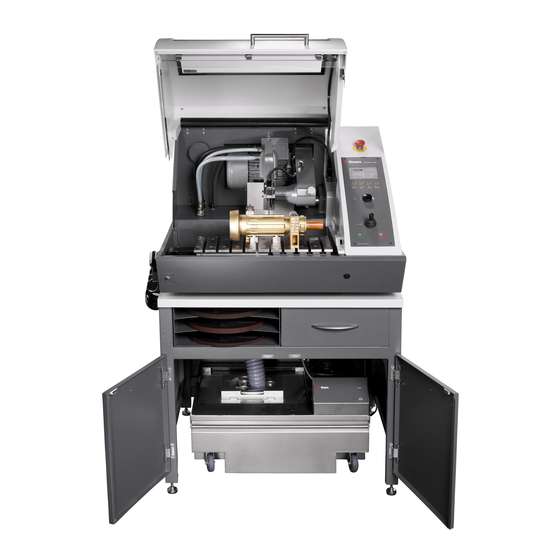
Discotom-100 /-10 Instruction Manual Take a moment to familiarise yourself with the location and names of Getting Acquainted the Discotom’s components. with Discotom Front View Control panel Cutting arm Turn /Push Knob Joystick for table movement ... - Page 15 Discotom-100 /-10 Instruction Manual Side view, right Emergency stop Main power switch The main switch is located on the right hand side of Discotom. Turn clockwise to switch on the power. Rear View Cooli unit connection ...
-
Page 16: Two-Handed Operation
Discotom-100 /-10 Instruction Manual When moving the cut-off wheel whilst the cover is open, the button Two-handed Operation on the front of Discotom must be pressed and held just before the joystick is operated. Press and hold the button, then move the joystick. -
Page 17: Power Supply
Check that the mains voltage corresponds to the voltage stated on the type plate on the side of the machine. Open the electric connection box and connect a 4-lead or 5-lead Discotom-100 / -10 cable* in the following way: PE: earth... - Page 18 Switch phases L1 and L2 Important: For Electrical Installations with Residual Current Circuit Breakers For Discotom-100 connected to electrical installations with residual current circuit breakers, a residual current circuit breaker, type B time delayed, 30 mA is REQUIRED (ref. EN 50178 / 5.2.11.1).
-
Page 19: Connection To An External Exhaust System
Discotom-100 /-10 Instruction Manual Struers recommends the use of an exhaust system, as workpieces Connection to an External may emit harmful gases when cut. The exhaust system will also Exhaust System reduce the level of water condensation on the sides of the cover. -
Page 20: Connecting A Recirculation Cooling Unit
Discotom-100 /-10 Instruction Manual To ensure optimal cooling, Discotom must be fitted with a Connecting a Recirculation recirculation cooling unit. Cooling System 4 is a configuration Cooling Unit designed for use with Discotom. Note: Cooling System 4 includes a static filter. -
Page 21: Basic Operation
Discotom-100 /-10 Instruction Manual 2. Basic Operation Using the Controls Front Panel Controls of Discotom... -
Page 22: Front Panel Controls
Discotom-100 /-10 Instruction Manual Front Panel Controls Name Item Function Name Item Function The Discotom display. Moves one step backward in menus. If modified parameters have not been stored, DISPLAY ESCAPE changes are lost. Menu dependent multi-function Multifunction knob. -
Page 23: Flush Hose
Discotom-100 /-10 Instruction Manual Press down the button on the top of the handle, to adjust the Flush Hose water flow. For instructions on how to use the flushing hose when cleaning the Discotom, see “Cleaning of Flush Hose Nozzle”. -
Page 24: Reading The Cutting Display
Discotom-100 /-10 Instruction Manual The Cutting Display displays three types of information: Reading the Cutting Display A: Cutting Parameters B: Motor Information Cutting Parameters In Automatic Cutting mode, the upper area of the display (A) displays information about the Cutting Parameters: Feed speed and Stop position. -
Page 25: Reading The Display
Discotom-100 /-10 Instruction Manual The display on the front panel provides different levels of status Reading the Display information. For example, when the machine is switched on using the Mains switch, the display informs you about the physical configuration of the Discotom and the version of software that is... - Page 26 Discotom-100 /-10 Instruction Manual The display is primarily divided into 2 areas. The position of these areas and the information they contain are explained in the illustration below, which uses the Options menu as an example: Heading: this is a navigational aid, telling you where you are in the software’s hierarchy.
-
Page 27: Manoeuvring In The Menu Structure
Discotom-100 /-10 Instruction Manual To select items in the menu: Manoeuvring in the Menu Structure Turn knob to select a menu, method group or a parameter. Push knob to open or activate the selection. Press Esc to return to the Main menu. -
Page 28: Software Settings
Discotom-100 /-10 Instruction Manual When switching Discotom on for the first time, the Select language Software Settings screen will appear (to change the language after this, see “Changing Language)”. Turn knob to select the language you prefer. Push knob to accept the language. - Page 29 Discotom-100 /-10 Instruction Manual Push knob to accept the settings. When Time and Date have been set, turn knob to select Save and Exit. Push knob to Save and Exit (Save the settings and return to the Main menu). The Main menu now appears in the language you have...
- Page 30 Discotom-100 /-10 Instruction Manual During normal operation, immediately after start up, where the splash screen is displayed, the software goes to the screen that was used before the machine was switched off. Thus you can continue exactly where you left last time the machine was used.
-
Page 31: Changing The Language
Discotom-100 /-10 Instruction Manual Changing the Language Turn the knob to select Configuration. Push knob to activate the Configuration Menu. Turn the knob to select Options Push knob to activate the Options Menu. Turn knob to select Language. - Page 32 Discotom-100 /-10 Instruction Manual Push knob to activate the Select language pop-up menu. Turn knob to select the language you prefer. Push knob to accept the language.
-
Page 33: Editing Numeric Values
Discotom-100 /-10 Instruction Manual The Configuration menu now appears in the language you have chosen. Check if there are any other settings that need changing in the Options menu. If not, Push ESC to return to the Configuration menu. Otherwise use the Turn/Push knob to select and change the required parameters. -
Page 34: Editing Alphanumeric Values
Discotom-100 /-10 Instruction Manual Note: If there are only two options, the popup box is not displayed. Pressing the knob (Enter) will toggle between the 2 options. Turn knob to increase or decrease the numeric value (or to toggle between the two options). - Page 35 Discotom-100 /-10 Instruction Manual Push knob to toggle between the 2 options. Note: If there are more than two options, a popup box is displayed. Turn knob to select the correct option. Press Esc to accept the option and return to the previous menu Or turn knob to select and edit other options in the menu.
-
Page 36: Operation Mode
Discotom-100 /-10 Instruction Manual In Operation mode 3 different user levels can be set. Operation Mode Production: Methods can be selected and viewed but no editing is possible. Development: Methods can be selected, viewed and edited Configuration: Methods can be selected, viewed and edited and all functions in Configuration are accessible. -
Page 37: New Pass Code
Discotom-100 /-10 Instruction Manual Select the desired operation mode and push knob to confirm. A New pass code can also be set in the Operation mode menu. New Pass Code Please Note When a pass code is set, the operator has 5 attempts to enter the correct pass code after which the Discotom will be locked. -
Page 38: Changing Cutting Mode And Cutting Parameters
Discotom-100 /-10 Instruction Manual Changing Cutting Mode and Cutting Parameters Discotom has two cutting modes: Automatic and Manual. Changing Cutting Mode To change between these two modes: Press Esc to go to the Main menu. Turn knob to select either Automatic cutting methods or... -
Page 39: Changing Cutting Parameters
Instruction Manual In automatic cutting mode Discotom applies the selected cutting Changing Cutting Parameters parameter values for: Wheel type, Wheel speed (Discotom-100 only), Cutting mode, Feed speed, MultiCut (with automatic x-table only) and Stop mode. To adjust the values of these parameters: ... - Page 40 Discotom-100 /-10 Instruction Manual Turn knob to highlight the category of wheel to be used (300 mm wheels are only available on Discotom-100). Push knob to display the cut-off wheels available. Turn knob to select the correct cut-off wheel.
- Page 41 Discotom-100 /-10 Instruction Manual The selected cut-off wheel is now displayed, and at the same time the rotational speed of the wheel is inserted. Intelligent speed adjustment To use the intelligent speed adjustment: (Discotom-100 only) Having selected a cut-off wheel as shown in:...
- Page 42 Discotom-100 /-10 Instruction Manual Turn knob to select the correct cut-off wheel. Push knob to activate the intelligent adjustment. Turn the knob left or right to select the Vickers hardness of the material you want to cut. The rpm setting for the cut-off wheel is changed accordingly.
- Page 43 Discotom-100 /-10 Instruction Manual Push knob to store the changed speed. Both the correct cut-off wheel and the adjusted wheel speed are saved to the cutting method.
-
Page 44: Changing The Wheel Speed
Discotom-100 /-10 Instruction Manual Changing the Wheel Speed To change the cut-off wheel speed: (Discotom-100 only) Turn knob to highlight the speed parameter. Push knob to edit the wheel speed. Turn knob to change the wheel speed (1500 to 3000 rpm) Push knob to store the selected wheel speed. -
Page 45: Selecting The Cutting Mode
Discotom-100 /-10 Instruction Manual To change the cutting mode: Selecting the Cutting Mode Turn knob to highlight the cutting mode parameter. Push knob to toggle the cutting mode. Push knob to store the selected cutting mode. Direct cutting Direct cut is the normal and most economic cutting mode that should be used for most cutting operations. - Page 46 Discotom-100 /-10 Instruction Manual Setting the Feed Speed To set the Feed speed: Turn knob to highlight the feed speed parameter. Push knob to edit the feed speed. Turn knob to change the feed speed. Push knob to store the new Feed speed value.
- Page 47 Discotom-100 /-10 Instruction Manual Selecting MultiCut To select the correct MultiCut mode: (Discotom with automatic x-table only) Turn knob to highlight the MultiCut parameter. Push knob to open the MultiCut menu. Turn knob to select the required MultiCut mode.
- Page 48 Discotom-100 /-10 Instruction Manual Icon Mode Single cut. MultiCut 1 Cut up to 10 slices of equal thickness MultiCut 2 Cut up to 10 slices of varying thickness MultiCut 3 Cut up to 10 slices of varying thickness counted from a common 0-position...
- Page 49 Discotom-100 /-10 Instruction Manual Selecting a Stop Mode To select Stop mode: Turn knob to highlight the stop mode parameter. Push knob to display available modes. Turn knob to highlight the mode to be used. Push knob to select highlighted mode.
-
Page 50: Stop Modes
Discotom-100 /-10 Instruction Manual Discotom has 3 different stop modes: Stop Modes Auto Relative Absolute When Auto stop mode is selected, the machine automatically stops Auto when the workpiece has been cut through. For normal cutting, Auto stop is recommended. - Page 51 Discotom-100 /-10 Instruction Manual When cutting is started, the bar indicating the travel of the cutting table is grey, until the motor current exceeds the required value. The bar then changes to green to signal that Auto mode is enabled.
-
Page 52: Relative Stop Position
Discotom-100 /-10 Instruction Manual The Y-table is set to stop in a position relative to where cutting starts. Relative Stop Position After entering the stop position (approximate sample size + wheel wear) the cutting process will be stopped as soon as the specified position has been reached. -
Page 53: Absolute Stop Position
Discotom-100 /-10 Instruction Manual The Y-table is set to stop in a fixed position measured from the zero Absolute Stop Position position where the cutting table is at the very front of the cutting chamber. The positioning range is 0-200 mm. -
Page 54: Using Motor Load And Temperature Display
Discotom-100 /-10 Instruction Manual The motor load and temperature values displayed are relative Using Motor Load and percentage (%) values. Temperature Display Manual Cutting Mode Motor load and temperature displays indicate how much force is being applied to the workpiece and how hot the motor is. As more force is applied, motor load is increased resulting in a higher temperature. -
Page 55: Fitting Or Changing The Cut-Off Wheel
Discotom-100 /-10 Instruction Manual Fitting or Changing the IMPORTANT The spindle of the Discotom is a left-hand thread. Cut-off Wheel Use the cutting arm to move the cut-off wheel into the top position and activate the cutting arm brake. -
Page 56: Starting/Stopping The Cutting Process
Discotom-100 /-10 Instruction Manual Automatic cutting the cut-off wheel is stationary and the cutting Starting/Stopping table moves. the Cutting Process Manual cutting the cutting table is stationary and the operator moves the cut-off wheel. Clamp the workpiece. Automatic Cutting ... -
Page 57: Manual Cutting
Discotom-100 /-10 Instruction Manual Clamp the workpiece. Manual Cutting Release the cutting arm brake. Position the cutting table and the workpiece under the cut-off wheel with the Y-table joystick. Note The workpiece should be positioned slightly in front of the cut-off wheel center. -
Page 58: Routine Maintenance
Accumulated dirt and swarf can restrict or cause damage to the movement of the cutting table. To ensure a longer lifetime for your Discotom Struers strongly recommends daily cleaning of the cutting chamber. Clean the cutting chamber thoroughly if the Discotom is not to be used for a longer period of time. -
Page 59: Daily Service
Discotom-100 /-10 Instruction Manual Daily Service Cleaning the Cutting Chamber Clean the cutting chamber both automatically (using AxioWash) and then manually (using the flushing gun). Automatic Cleaning: AxioWash To start the AxioWash function: Remove the workpiece and tools from the cutting chamber. -
Page 60: Weekly Maintenance
Replace the cooling water in the Recirculation Cooling Unit at Replacing the Cooling Water least once a month. To maintain the optimum performance of Discotom-100/ -10, Lubricating the Cutting Table lubricate the cutting table at regular intervals (approx every 100 hours). -
Page 61: Yearly Service
Carry out inspection at more regular intervals if Discotom is used for more than one 7 hour shift a day. Struers recommends that the PETG glass in the cover is replaced after 5 years of routine operation. The cover should be replaced immediately if it has been weakened... - Page 62 Discotom-100 /-10 Instruction Manual Reference Guide Table of Contents Page 1. Advanced Operations Configuration Menu ................57 Selecting and Using the Configuration Menu ......57 Configuration Parameters ............59 MultiCut 1 (option) ................62 MultiCut 2 (option) ................64 MultiCut 3 (option) ................66 MultiCut 4 (option) ................
-
Page 63: Advanced Operations
Discotom-100 /-10 Instruction Manual 1. Advanced Operations Configuration Menu From the Main menu select Configuration and push the Selecting and Using the knob to activate the Configuration menu Configuration Menu Select Options and push the knob to activate the Options menu. - Page 64 Discotom-100 /-10 Instruction Manual...
-
Page 65: Configuration Parameters
Discotom-100 /-10 Instruction Manual Configuration Parameters Display brightness: The contrast settings of the display can be adjusted to suit individual preferences (range 0-100). Language: The language can be set to English (default), German, French, Spanish, Japanese, Chinese, Italian, Russian or Korean. - Page 66 Discotom-100 /-10 Instruction Manual From the Main menu select Configuration and push the User defined cut-off wheels knob to activate the Configuration menu Select User defined cut-off wheels and push the knob to activate the User defined cut-off wheels menu.
- Page 67 Discotom-100 /-10 Instruction Manual Push knob to save the new cut-off wheel.
-
Page 68: Multicut 1 (Option)
Discotom-100 /-10 Instruction Manual The MultiCut 1 mode permits the cutting of up to 10 samples of equal MultiCut 1 (option) width. To set up cutting using MultiCut 1 mode: Select MultiCut1 Select a cutting method and turn the knob until the MultiCut icon is highlighted, push the knob to display the Select MultiCut mode menu. - Page 69 Discotom-100 /-10 Instruction Manual Setting the parameters Turn the knob to select a parameter. Press the knob to edit the parameter. Sample width This parameter sets the width of the samples that will be cut. No. of samples This parameter sets the number of samples that will be cut.
-
Page 70: Multicut 2 (Option)
Discotom-100 /-10 Instruction Manual The MultiCut 2 mode permits the cutting of up to 10 samples of MultiCut 2 (option) different widths. To set up cutting using MultiCut 2 mode: Select MultiCut 2 Select a cutting method and turn the knob until the MultiCut icon is highlighted, push the knob to display the Select MultiCut mode menu. - Page 71 Discotom-100 /-10 Instruction Manual Setting the cutting parameters Turn the knob to select a parameter. Press the knob to edit the parameter. No. of samples This parameter indicates the number of samples that will be cut. This parameter sets the width of the samples that will be cut.
-
Page 72: Multicut 3 (Option)
Discotom-100 /-10 Instruction Manual The MultiCut 3 mode allows carrying out up to 10 cuts at different MultiCut 3 (option) relative distances from the ‘zero’, or starting position. The distances are manually entered into the Discotom. To set up cutting using MultiCut 3 mode: Select MultiCut 3 ... - Page 73 Discotom-100 /-10 Instruction Manual Setting the cutting parameters Turn the knob to select a cutting position. Press the knob to edit the position and do that for all the cutting positions required.. Cutting position (Relative) This parameter sets the position of the cuts. The values show the relative distance to the zero position.
-
Page 74: Multicut 4 (Option)
Discotom-100 /-10 Instruction Manual The MultiCut 4 option allows carrying out cutsat different relative MultiCut 4 (option) distances from the ‘zero’, or starting position. The distances are entered into the Discotom by using the X-table to position the workpiece in front of the cut-off wheel where the sample is to be cut and then recording this position. - Page 75 Discotom-100 /-10 Instruction Manual Setting the cutting parameters Position the workpiece relatively close to the cut-off wheel and clamp it. Use the joystick to move the X-table to the position where the first cut is to be made.
-
Page 76: Clamping Irregular Workpieces
This could result in damage to the cut-off wheel or to the sample itself. Use the T-slots to mount the special clamping tools. Struers offers a large selection of Clamping Tools (See “Accessories”). To achieve faster cutting, position the workpiece so that the wheel... -
Page 77: Optimising Cutting Results
Increase feed speed in discoloration and vibrations? steps of 0.1 m/s. unplane cuts. Major vibrations: May cause sample Increase rotational speed discoloration and by 500 rpm. (D-100 only). unplane cuts. Please refer to the Selection Guide in the Struers Struers Cut-off Wheels brochure. -
Page 78: Explanation Of Safety Factors
Discotom-100 /-10 Instruction Manual The cover has a safety switch to prevent the cut-off wheel from Explanation of Safety Factors starting while the cover is open. Furthermore, a locking mechanism prevents the operator from opening the cover until the cut-off wheel... -
Page 79: Accessories
Discotom-100 /-10 Instruction Manual 2. Accessories Please refer to the for details of the Discotom-100 /-10 brochure range available. Clamping Tools Please refer to the for details of the Struers Clamping Tools brochure range available. -
Page 80: Consumables
The warranty may not cover damaged machine parts (e.g. seals and tubes), where the damage can be directly related to the use of non-Struers consumables. Cut-off Wheels Please refer to the Selection Guide in the Struers Struers Cut-off Wheels brochure. -
Page 81: Trouble-Shooting
Remove the excess water in the tank. tank. Workpieces or cutting chamber Insufficient additive in cooling fluid. Use Struers Additive for cooling rusty. fluid in the cooling water, at the correct concentration. Check with a refractometer. Follow the instructions in the ‘Maintenance’... - Page 82 Discotom-100 /-10 Instruction Manual Error Explanation Action Cutting Problems Discoloration or burning of the The hardness of the cut-off wheel is Reduce rotational speed (D-100 workpiece. inappropriate for the hardness / only) or change wheel. See dimensions of the workpiece.
- Page 83 Leave the cover open when you leave the machine. Insufficient additive for cooling fluid. Use Struers Additive for cooling fluid in the cooling water at the correct concentration. Check with a refractometer. See “Maintenance”...
-
Page 84: Error Messages
Discotom-100 /-10 Instruction Manual Error messages are divided into two classes: Error Messages Messages Errors Messages Messages are intended to inform the operator of the machine’s progress and advise about minor operational errors. Errors Errors must be rectified before cutting can be continued. -
Page 85: Maintenance
Discotom-100 /-10 Instruction Manual 5. Maintenance Struers recommends that a regular service check be carried out after Service Info every 1500 hours of use. Information on total operation time and servicing of the machine is displayed on the screen at start-up: A pop-up message will appear after 1,000 hours operation time to remind the user that a service check should be scheduled. -
Page 86: Maintenance Of Cutting Table
Discotom-100 /-10 Instruction Manual Maintenance of Cutting Table The stainless steel bands are available as spare parts and should be replaced if they become worn or damaged. To allow humidity to escape from the cutting table and chamber, it is recommended to leave the cover open when the machine is not in use. -
Page 87: Reset Functions
Discotom-100 /-10 Instruction Manual It can become necessary to reset certain functions to the factory Reset Functions settings using the Reset functions menu. To reset methods or configuration: Go to the Maintenance menu and select: Reset functions. Select Reset methods to delete all cutting methods at once. -
Page 88: Service Information
Various topics can be selected for information on the condition of the different components. Service information can also be used in cooperation with a Struers service technician for remote diagnostics of the equipment. Service information is read-only information; machine settings cannot be changed or modified. -
Page 89: Technical Data
ø 3.70” with 2.4”flange Discotom-10 ø 94 mm with 61 mm (ø 250 mm/10" cut-off wheels) flange PHYSICAL SPECIFICATIONS Cutting Motor Discotom-100 (50-60 Hz) Cutting power, constant [S1] 4 kW 5.4 HP 4.7 kW Cutting power, intermittent [S3] 6.4 HP Maximum power 6.8 kW... - Page 90 Discotom-100 /-10 Instruction Manual Subject Specification Metric/International x-table (option) Width x Depth 282x270 mm 11.1 x 10.6" x-table range 100 mm 3.9" T-slots 10 mm 0.39" Width 920 mm 36.2" Dimensions Depth 890 mm 35.0" and Weight Height (closed/open cover) 685 / 1080 mm 27 / 42.5"...
- Page 91 Discotom-100 /-10 Instruction Manual Subject Specification ELECTRICAL DATA *Important: Local standards may overrule the recommendations for the main supply cable. If necessary, please contact a qualified electrician to verify which option is suitable for the local installation setup. Discotom-100 Mains Cable...
- Page 92 Discotom-100 /-10 Instruction Manual Subject Specification Discotom-10 Mains Cable Voltage / frequency: Main supply connection Specification* Min. Minimum cable Max. Minimum cable Fuse size Fuse size size @ Min. fuse size @ Max. fuse 3 x 200 V / 50 Hz 3x 2,5 mm²...
-
Page 93: Cutting Capacity
Discotom-100 /-10 Instruction Manual The graph shows the projected cutting capacity under the following Cutting Capacity conditions: A new cut-off wheel. The workpiece is laid directly on the cutting table, with overhang where appropriate. Vertical clamping is used. The actual cutting capacity depends on the sample material, cut-off... - Page 94 Discotom-100 /-10 Instruction Manual Quick Reference Guide Clamping the Workpiece Secure the workpiece using the clamping device of your choice, usually the quick-clamping device. Place the workpiece between the clamp and the backstop. Push the clamp towards the workpiece and lock the quick- clamping device with the locking handle.
- Page 95 Discotom-100 /-10 Instruction Manual Cleaning the Cutting Chamber Press the Flush key on the control panel to activate the recirculation pump. Lift the flushing gun from its holder. Point the flushing gun towards the bottom of the cutting chamber.
Need help?
Do you have a question about the Discotom-100 and is the answer not in the manual?
Questions and answers