Table of Contents
Advertisement
Quick Links
Advertisement
Table of Contents

Related Manuals for PowerTec 71402


Summary of Contents for PowerTec 71402
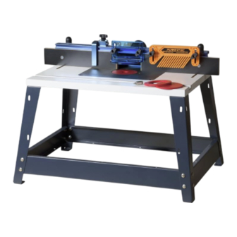
- Page 1 Model No.71402 Owner's Manual Bench Top Router Table and Fence Visit us on the web at www.powertecproducts.com You will need this manual for safety instructions, operating procedures, and warranty. Put it and the original sales invoice in a safe, dry place for future reference.
-
Page 2: Table Of Contents
TABLE OF CONTENTS PRODUCT SPECIFICATIONS SECTION PAGE RECOMMENDED ROUTER BIT SPEEDS SAFETY RULES / WARNINGS BIT DIAMETER MAXIMUM SPEED General Tool Safety Up to 1" (25 mm) ..... .22,000 -24,000 rpm Tool Specific Warnings 1"... -
Page 3: Safety Rules / Warnings
SAFETY RULES FOLLOW ALL STANDARD SHOP SAFETY WARNING PRECAUTIONS, INCLUDING: For your own safety, read all of the rules and precautions before • Keep children and visitors at a safe distance from work area. operating tool. • Keep work area clean. Cluttered work areas invite accidents. WARNING Work area should be properly lit. - Page 4 SPECIFIC SAFETY WARNINGS • Never use dirty, dull, or damaged router bits. Remove DANGER wood-resin build-up with a cleaner specifically formulated for cutting tools. Have dull bits sharpened by a qualified person. • To avoid serious injury, keep hands and fingers away from the Discard damaged bits.
- Page 5 • Extension cords must be a minimum of 16 AWG and be rated questions relative to the application of the router table, DO for the equipment in use. NOT use it until you have contacted POWERTEC and have been advised accordingly. • Use a separate electrical circuit for your tools. This circuit must not be less than a #12 wire and should be protected with a 15 A time-delayed fuse.
-
Page 6: Parts And Contents
ASSEMBLY PARTS AND CONTENTS UNPACKING Check for shipping damage. Check immediately whether all parts and accessories are included. Table Assembly Fence Assembly Refer to Figure 1 Refer to Figure 2 Shows the contents off the table assembly Shows the contents off the fence assembly ITEM DESCRIPTION ITEM DESCRIPTION Legs... - Page 7 TABLE ASSEMBLY ASSEMBLE BENCH TOP ROUTER TABLE Figure 4 Model No. 71402 Top (with wood top) 23-5/8" x 15-3/4" (600x400mm) Leg Spacing 27-1/8" x 19-1/4" (689x489mm) Height (with wood top) C 15-1/2" (394mm) Shelf 23-5/8" x 15-3/4" (600x400mm) Shelf Height 14-1/2"...
- Page 8 Router Drill Patterns For routers not covered by the Chart follow the instructions below Figure 7 With target pattern facing up—place insert plate (MM) onto workbench. (Figure 8) a. Remove sub-base from router. Check router base holes to ensure alignment with any of the center point patterns. If so, use that pattern.
- Page 9 IMPORTANT: Store the router sub-base in a convenient place. It will be needed when removing router from the router table and for handheld routing. 2. Using the screws that attached the sub-base to the router, attach the router base to the insert plate (MM). NOTE: Depending on the thickness of your router sub-base, it may be necessary to purchase longer screws.
-
Page 10: Fence Assembly
FENCE ASSEMBLY Refer to Figure 11–13 • Place a spacer on each 5/16"-18 x 1-1/2" long T-Bolt and insert through the slot in the featherboard, thread a locking knob on • Remove the adhesive backing from the right to left tape each T-Bolt and slide the T-Bolts into the T-slot in the front of measure and press into place. - Page 11 Figure 12 FRONT ADJUSTING THE FENCE FACES Figure 13 Refer to Figure 14 The two MDF adjustable fence faces are designed to slide about 2" along the fence. This allows the opening for the router bit to be adjusted from 0" up to 4". Generally, the infeed and outfeed adjustable fence faces should be adjusted as close to the bit as possible without contacting the cutter.
-
Page 12: Operation
GENERAL ROUTING ROUTING JOINTING 1. Use the insert-plate reducing ring with the smallest opening Refer to Figure 16–19 that allows the bit to pass through it. Position the fence faces The independently adjustable fence faces allow the router table as close as possible to the bit. Turn the bit by hand to check to be used as a vertical jointer by offsetting the outfeed fence for interference. -
Page 13: Maintenance
Figure 19-a Figure 19-b (Top View with workpiece) 3. Install a straight bit in the router. Place a straight edge against the outfeed fence face and position the fence so the bit just grazes the straight edge. NOTE: Make sure all rods are clear of cutter. Always use a scrap piece of wood to test the setup. -
Page 14: Notes
NOTES... -
Page 15: Warranty
30-DAY SATISFACTION GUARANTEE POLICY During the first 30 days after the date of purchase, if you are dissatisfied with the performance of this POWERTEC tool for any reason, you may return the tool to the retailer from which it was purchased for a full refund or exchange. You must present proof of purchase and return all original equipment packaged with the original product. - Page 16 Southern Technologies, LLC Chicago, IL 60606...
Need help?
Do you have a question about the 71402 and is the answer not in the manual?
Questions and answers