Table of Contents
Advertisement
Quick Links
Advertisement
Table of Contents

Related Manuals for FineTek EPF Series


Summary of Contents for FineTek EPF Series
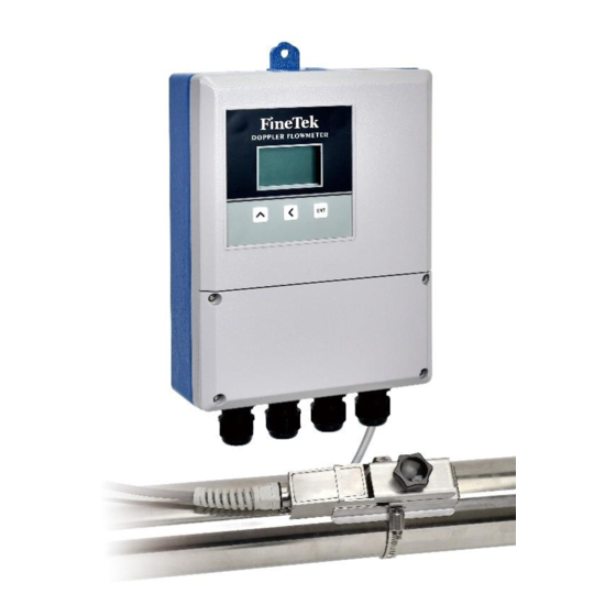
- Page 1 EPF Doppler Ultrasonic Flowmeter Operations Manual FineTek Co.,Ltd. No.16, Tzuchiang St., Tucheng Industrial Park, New Taipei City 23678 Tel:886-2-22696789 Fax:886-2-22686682 Website:http://www.fine-tek.com E-mail:info@fine-tek.com 08-EPF-B1-KM,10/04/2023...
-
Page 2: Table Of Contents
Contents 1. Operation manual use ....................3 2. Product warranty ......................4 2.1 New product warranty ....................4 2.2 Repair warranty ......................4 2.3 Service Network ....................... 5 3. Product Inspection ....................... 6 3.1 Product Check ......................6 3.2 Safety Inspection ...................... 6 3.3 Handling and Carrying .................... - Page 3 10. Description of panel functions ................20 10.1 Description of display interface ................20 10.2 Description of push key ..................20 10.3 Menu setting process instructions ................ 20 10.4 Quick setup process ..................... 21 10.5 Description of parameter setting function ............. 23 11.
-
Page 4: Operation Manual Use
➢ Please read this operation manual completely and carefully before installing the product. ➢ Please contact FineTek if this operation manual does not answer your questions. ➢ The content of this operation manual may be updated from time to time. Updates are Maintained on the FineTek website www.fine-tek.com... -
Page 5: Product Warranty
2. Product warranty 2.1 New product warranty ➢ Each FineTek EPF series paddlewheel flowmeter is backed by 1-year limited warranty. Should you experience a problem with one of our products deemed by our factory to be a product failure covered by our warranty, for a period of 1-year from the delivery date we will repair the unit at our factory or provide you with a replacement unit or sub-assembly at our discretion. -
Page 6: Service Network
Aplus FineTek 355 S. Lemon Ave, Suite 1 909 598 2488 1 909 598 3188 D, Walnut, CA 91789 (Sensor Inc.) FineTek Pte Ltd. 37 Kaki Bukit Place, Level 4 (Singapore +65 6452 6340 +65 6734 1878 Singapore 416215 Branch) Bei den Kämpen 26... -
Page 7: Product Inspection
3. Product Inspection 3.1 Product Check ➢ Doppler ultrasonic flowmeter transmitter: 1 set. ➢ Doppler ultrasonic sensor (including cable): 1 set. ➢ Sensor bracket: 1 group. ➢ Couplant for ultrasonic testing: 1. ➢ Operating instructions: 1 set. ➢ Imported product inspection form: 1 copy. 3.2 Safety Inspection ➢... -
Page 8: Storage And Transportation Requirements
4. Storage and Transportation Requirements 4.1 Environmental Requirements ➢ Rainproof and moisture-proof. ➢ During transportation, minimize vibrations and impact as much as possible. ➢ Applicable temperature range: 20~60 °C. ➢ Room humidity: less than 80%. ➢ If stored in the open, the flowmeter may not operate properly. 4.2 Handling Requirements To prevent the product from being damaged during delivery, please keep it in its original packaging state as packed by the manufacturer. -
Page 9: Product Introduction
5. Product Introduction 5.1 Features of the product ➢ When measuring the flow rate, you may start the measuring without the need of dismantling the pipeline and it will not adversely affect the original pipeline and the process fluid. ➢ The LCM display module can display the instantaneous flow rate and total flow rate. - Page 10 5.3 Product applications The Doppler Ultrasonic Flow Meter is mainly designed for measuring liquid that contains excessive impurities such as solid particles or bubbles and that is deeply contaminated. It is mainly applied in the following fields: ➢ Sewage, oily sewage, wastewater, and dirty circulation water; for example, the wastewater and sewage treatment plant.
-
Page 11: Specifications Of The Product
Note 1: The minimum size required for the solids or bubbles is 100µm and the minimum concentration is 75 ppm. Note 2: ◆ Physical water flow testing device manufactured by Finetek. Fluid temperature: 20±10°C; environment temperature: 20±5°C ◆ Length of straight piping section: Upstream – 15 D or over; downstream section: Over 5 D ◆... - Page 12 Note 3: The recommended economic flowing velocity should be over 1.5m/s. 30.0% 25.0% 20.0% 15.0% 10.0% 12.5% of F.S. = 1.5m/s 5.0% 0.0% 10.0 12.0 Standard meter flowing velocity (m/s)
-
Page 13: Outline Dimensions
6.2 Outline dimensions Transmitter Transducer (DN15~DN500) Transducer support unit... -
Page 14: Wiring Instructions
7. Wiring instructions 7.1 Electrical specifications – DC Input voltage: DC24V Input current: 200mA±20% 7.1.1 Instructions for wiring terminal Before each use, please follow the safety hint provided below: The wiring shall be allowed for the transducer under the power outage status. Power input Transducer wiring Transducer screen cable... -
Page 15: Electrical Specifications - Ac
7.2 Electrical specifications – AC Input voltage: AC100~240V 7.2.1 Instructions for wiring terminal Before each use, please follow the safety hint provided below: The wiring shall be allowed for the transducer under the power outage status. Input power Transducer wire Transducer screen cable Insulation layer color Insulation layer... -
Page 16: Installation Instructions
8. Installation instructions For detailed operating instructions and operating methods, please refer to the instructions provided below: ➢ Applicable regulations have been established for the design, testing and power supply of the flow meter. The users are required to comply with the provided instructions in order to maintain the safe operation and normal function of the flow meter. -
Page 17: Transducer Installation
9. Transducer installation 9.1 Select the installation position To avoid the measuring pipe not under low liquid level conditions, please install the transducer until reaching the constant full-load position being marked in the pipe (Fig. 1). Upward vertical flowing Upward inclined flowing Lowest point in the pipe system (Fig. - Page 18 ➢ The transducer should be installed in a position that is fully filled with the liquid in the pipe and it should not be installed in a position that is filled with the air or the sediment in the pipe (Fig. 3). The optimal installation scope of the transducer should be within ±45° and the maximum installation angle should be within ±60°.
- Page 19 Type Upstream straight pipe length Downstream straight pipe length 90 ̊ Elbow T-shape connector Expansion pipe Converging pipe Control valve Upstream flow rate control Downstream flow rate control Check Valve Shutoff Valve Pump (Fig. 5)
- Page 20 Transducer coupling agent coating method...
-
Page 21: Description Of Panel Functions
10. Description of panel functions 10.1 Description of display interface Instantaneous flow Total flow Signal intensity Operating key 10.2 Description of push key Parameter set interface Measuring Push key Menu Mode Read Only Digit Edit Mode List Edit Mode Main Page Access the ACK key (press ACK key (press... -
Page 22: Quick Setup Process
10.4 Quick setup process Set pipe ID (1) Set pipe ID, Measuring Page. Press and hold for 3 seconds to access Operation ACK page. Press to confirm the selection. (2) Press to access Main Menu. Select Basic Set. Press to access Basic Set and press for returning to the previous page. - Page 23 Set the Instantaneous Flow Unit and Set Total Flow Unit (1) Set the unit of flow. Select the unit of instantaneous flow and then press to access Instantaneous Flow Unit. Select according to the desired setting. (2) Set Total Flow Unit. Select cumulative total flow unit and then press to access.
-
Page 24: Description Of Parameter Setting Function
10.5 Description of parameter setting function Default Menu 1 Menu 2 Menu 3 Unit Set value scope Description of function Value Tag number for Device Tag Num 00001 1~65535 customer-end factory (1.1) management Pipe ID Set pipe ID to calculate Pipe ID (1.2) xxx.xx Unit... - Page 25 Default Menu 1 Menu 2 Menu 3 Unit Set value scope Description of function Value The initial status of the Pulse output contact or the flow rate is displayed with the frequency (if Pulse Out Mode 0.Pulse NO selecting the frequency, (3.2) 0.Pulse 1.Pulse NC...
- Page 26 Default Menu 1 Menu 2 Menu 3 Unit Set value scope Description of function Value Recover Default (4.4) Cancel Cancel, Accept (Recovery Default) LCM Brightness (4.5) Simulate the flowing speed for the system to Flow Speed make a corresponding (5.1) -15 ~ 15 reaction.
-
Page 27: Error Message And Troubleshooting
11. Error message and troubleshooting Failure Status Cause of failure Solution The transducer is installed at the The water flow Install the transducer at the position subjecting to stronger rate is abnormally location without a vibration pipeline vibration or causing the displayed. - Page 28 The measured material is excessively clean, or the content Replace it with a suitable of the solid suspension is too transducer. low. Install the transducer on the FRP Change the installation position. fabricated pipeline. When installing the transducer on the waterproof jacket or the pipeline wrapped with insulation Change the installation position.
- Page 29 ①Restart the transducer. The transducer is abnormal. ②Please contact this company to solve the problem. The transducer is not tightly fixed Check if it has been coated with to the pipeline. the coupling agent. Check if the liquid inside the Check if the liquid is presenting pipeline is presenting any any bubbles or particles.
-
Page 30: Modbus Communication Protocol
12. MODBUS Communication Protocol EPF Measuring System ModBus Communication Address (Auto ID)List Address Address Variable Name Data Type Unit Range Definition Authority (Hex) (Dec) Read only 0x1000 4096 gt_modbus_slave_fine_tek_id[0] UINT8 "IF" (Header) Read only 0x1001 4097 gt_modbus_slave_fine_tek_id[2] UINT8 "EN" (Header) Read only 0x1002 4098... - Page 31 Address(He Address( Variable Name Data Type Unit Range Definition Authority Dec) 0x1080 4224 Basic set/Pipe PFC_BASIC_SET_PIPE_ID FLOAT32 Read /Write ID set 0x1081 4225 Basic set/Pipe 0x1082 4226 PFC_BASIC_SET_PIPE_ID_UNIT UINT16 Read /Write ID Unit set PFC_SAVE_SYSTEM_VAR_TO_ Write in USER 0x10B0 4272 UINT16 0:Ide1, 1:Save Read /Write...
- Page 32 Address Address Variable Name Data Type Unit Range Definition Authority (Hex) (Dec) 0x10C6 4294 0x10C7 4295 PFC_ADVANCED_SET_LOW_CU Advanced FLOAT64 Read /Write TOFF Set/Low Cutoff 0x10C8 4296 0x10C9 4297 0x10CA 4298 Advanced 0x10CB 4299 PFC_ADVANCED_SET_SIGNAL_ FLOAT64 Set/Low Signal Read /Write CUTOFF 0x10CC 4300 Cutoff...
- Page 33 Address(He Address( Variable Name Data Type Unit Range Definition Authority Dec) System 0x10E0 4320 Set/System flow_velocity FLOAT32 Read /Write Info./ Current 0x10E1 4321 Flowing Speed System 0x10E2 4322 Set/System gf_pfc_flow_rate FLOAT32 Read /Write Info./ Current 0x10E3 4323 Flow Rate System 0x10E4 4324 Set/System...