
Related Manuals for FineTek EPD34


Summary of Contents for FineTek EPD34
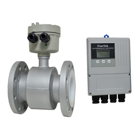
- Page 1 EPD34 Electromagnetic Flow Meter Operation Manual FineTek Co., Ltd. 08EPD34-B0-EK,12/20/2016...
-
Page 2: Table Of Contents
Contents 1. Reading Labels ........................1 2. Product Warranty ....................... 2 2.1 New Product Warranty ....................2 2.2 Repair Warranty ......................2 2.3 Service Network ......................3 3. Product Inspection ......................4 3.1 Check Content ....................... 4 3.2 Safety Inspection ......................4 4. - Page 3 12. Wiring and Using ......................20 12.1 Wiring ......................... 20 12.1.1 Notes for Wiring ....................20 12.1.2 Diagram of Sensor Wiring Terminal ..............20 12.1.3 Diagram of Transmitter Wiring Terminal ............21 12.1.4 Signal Electrical Cable Wiring ................22 12.2 Input / Output Function Wiring ................23 12.2.1 4-20mA Current output ..................
-
Page 4: Reading Labels
1. Reading Labels Thanks for purchasing FineTek’s Product. This operation manual describes the product features, working principles, operation and maintenance methods. It makes the user fully understand how to use the product correctly, so as to prevent dangerous situations such as device damage or operator injury. -
Page 5: Product Warranty
2. Product Warranty 2.1 New Product Warranty We don’t charge for the inspection, part/s and repair for the product of the company that has a defect within 12 months from the delivery date and meets the warranty terms. If the product defect is not due to human error during its transportation, user may change to a new unit from the company within 7 days from delivery date. -
Page 6: Service Network
Zhengzhou Sales office +86 0371-55638443 +86 0371-55638440 (China) Jianshe Road, Zhongyuan District, Zhengzhou City (450007) 60 Kaki Bukit Place #07-06, Finetek Pte Ltd. Eunos Techpark 2 Lobby B, +65 6452-6340 +65 6734-1878 (Singapore Branch) Singapore 415979.415979 Frankfurter Str. 62, OG D-65428... -
Page 7: Product Inspection
3. Product Inspection 3.1 Check Content 1 flow meter 1 operation manual 1 product inspection sheet 3.2 Safety Inspection Please check whether the external package is deformed or damaged. Please remember to take a picture for evidence for compensation later. ... -
Page 8: Product Features
5. Product Features The measurement results is not affected by the change of liquid density, viscosity, temperature, pressure and conductivity. There are only two measurement points in the measuring tube without baffle and movable parts, so it won’t cause pressure loss and jam. ... -
Page 9: Working Principles
8. Working Principles The working principle of the electromagnetic unit is based on the Faraday law of electromagnetic induction. When the conductor moves in the magnetic field, it will generate induced EMF on both sides of the conductor in the orthogonal direction of the magnetic field direction and the motion direction. -
Page 10: Technical Performance
9. Technical Performance 9.1 Execution Standards IEC 60068-2-3 EN 61326-1:2013 IEC 61326-1 EN 55011:2009/A/:2010 IEC 60092-504 ISO 4064-1 JIS B2220 JIS B7554-1997 ANSI B16.5 DIN 25 Series... -
Page 11: Basic Parameters And Performance Indicators
Input power AC100~240Vac Power consumption <10 W Wire inlet specification M20 x1.5*2 Female signal power cable < 100m *Note 2 Excitation mode Pulse DC Vibration regulation IEC 60068-2-3 EMC regulation IEC/EN 61326-1 Class A table 2 Note 1:Combined with FineTek sensor... -
Page 12: Accuracy Class & Tolerance
Note 2:When the signal power cable is longer than 50m, the empty tube detection is unavailable. 9.2.2 Accuracy class & tolerance 9.2.3 Recommended Flow Range for Tube Diameters Flow range (m / h) Pipe diameter (mm) Flowing speed 0.1~1.0m/s Flowing speed 1.0~10m/s 0.45~4.5 4.5~45.2 0.71~7.1... -
Page 13: Pressure Resistance And Inner Diameter Specification For Various Tube Diameters
9.2.4 Pressure resistance and inner diameter specification for various tube diameters Inner diameter of measurement tube Specification of Nominal diameter measurement tube PTFE Inch Inch Inch 1-1/4 1-1/2 1.50 1.93 2-1/2 2.52 3.03 4.02 5.04 5.94 8.15 10.08 11.85 9.2.5 Lining Material Lining material Main properties Application scope... -
Page 14: Electrode Material
9.2.6 Electrode Material Electrode material Anti-corrosion property Stainless steel (316L) It is applied in water, sewage and organic corrosive medium. It is resistant to the corrosion of the medium mixture of oxidizing acid such as Nitric acid, mixed acid or Sulfuric acid. Moreover, it is resistant Hastelloy alloy to the corrosion of the oxidizing salt such as or other... -
Page 15: Appearance And Dimension
10. Appearance and Dimension 10.1 JIS 10K & 20 K JIS 10K Connection specification Nominal diameter(mm) PTFE Lining material Length ϕD External diameter ϕC Flange thickness Inclined angle of screw θ° 22.5 22.5 22.5 22.5 11.25 hole θh Diameter of screw hole Quantity of screw holes Height of sensor casing 303.9... -
Page 16: Ansi 150Lbs & 300Lbs
10.2 ANSI 150Lbs & 300Lbs Connection specification ANSI 150Lbs Nominal diameter(mm) Lining material PTFE Length ϕD 279.4 342.9 406.4 482.6 External diameter ϕC 98.4 120. 139.7 152.4 190.5 215. 241.3 298.4 361.9 431.8 15.9 17.4 20.6 22.2 22.2 22.2 23.8 27.0 28.6 30.2... -
Page 17: Din Pn40 & Pn16 & Pn10
10.3 DIN PN40 & PN16 & PN10 Connection specification DIN PN40 DIN PN16 Nominal diameter(mm) Lining material PTFE Length ϕD External diameter ϕC Flange thickness Inclined angle of θ° 22.5 22.5 22.5 22.5 22.5 22.5 screw hole θh Diameter of screw hole Quantity of screw holes... -
Page 18: Installation
11. Installation The design, test and power supply for the flow meter are based on the related regulations. User must strictly follow the instructions to guarantee the safe operation and normal working of the flow meter. 11.1 Conditions required to guarantee the measurement accuracy of the electromagnetic flow meter: ... -
Page 19: Handling
11.4 Handling The flow meter must be handled with the correct handling method. The safety load and protection action of the handling equipment should meet the related regulations. The transmitter box (for integrated flow meter) or enclosure (for separated flow meter) must not be tied up to handle the flow meter. - Page 20 d. The flowing direction of the fluidic is the same as the arrow direction on the flow meter. e. Please prevent the vacuum in the pipe, which will damage the lining of the flow meter. f. The flow meter must be free from strong electromagnetic field. The magnetic intensity of the flow meter installation site must be smaller than 400A/m.
-
Page 21: Notes For Installation On The Pipe
11.6 Notes for Installation on the Pipe When installing the flow meter, one must follow the installation diagrams as shown below. This will ensure the flow meter can guarantee the pipe is always filled with the liquid: (The figures below are only typical cases, which don’t include all feasible installation methods. -
Page 22: Grounding Requirements
11.7 Grounding Requirements The grounding of the electromagnetic flow meter is very important. If the grounding is poor, it won’t work normally. The sensor and transmitter should be equipped with high-quality independent grounding wire (The section area of the copper core is 1.6mm ). -
Page 23: Wiring And Using
12. Wiring and Using 12.1 Wiring 12.1.1 Notes for Wiring It is recommended to select 2-core insulation rubber cable, with the external diameter larger than 10mm. For AC power supply, L1 should be connected with “Live Wire”. The wiring for all terminal blocks should be clapped with the flathead terminal and insulated. -
Page 24: Diagram Of Transmitter Wiring Terminal
12.1.3 Diagram of Transmitter Wiring Terminal Power Cable of Excitation Signal Signal Measurement Power Cable Terminal Terminal Description Description Name Name Excitation Signal Wire Detection Signal Wire E1 Detection Signal Excitation Signal Wire Shielded Wire Signal Shielded Wire Detection Signal Wire E2 Detection Signal Shielded Wire Signal Shielded Wire... -
Page 25: Signal Electrical Cable Wiring
12.1.4 Signal Electrical Cable Wiring Excitation Signal Wire The bare wire shield part should be added with heat-shrink tube S: Signal S: Signal protection wire protection wire Cut the shield in Cut the shield in the inner layer the inner layer Excitation signal wire (Sensor end) Excitation signal wire (Transmitter end) (Unit: mm) -
Page 26: Input / Output Function Wiring
12.2 Input / Output Function Wiring 12.2.1 4-20mA Current output Specifications: Output mode: Active Max load impedance: 700Ω Max output current: 24mA 12.2.2 Pulse Output Specifications: Output mode: Passive Max output voltage: 32 VDC Max input current: 200mA (Protection) Max working frequency: < 8000 Hz Min pulse width: 0.0625 ms Pulse width control: Auto 50% duty 12.2.3 RS-485 Communication... -
Page 27: Digital Output 1 (Do1)
12.2.4 Digital output 1 (DO1) Specifications: Output mode : Inactive Max input voltage : 32VDC Max input current : 200mA (protected) 12.2.5 Digital output 1 (DO2) Specifications: Output mode : Inactive Max input voltage : 32VDC Max input current : 200mA (protected) 12.2.6 Digital input (DI) Specifications: Input mode: Dry-Contact... -
Page 28: Analogy Input (Ai)
12.2.7 Analogy input (AI) Specifications: Max input current: 24mA Input impedance: 100Ω 13. Inspection before Power-On 1. Check whether the flow meter is damaged during transportation and installation. 2. Check whether the voltage of the power supply is consistent with that specified on the nameplate. -
Page 29: Parameter Functions
14. Parameter Functions 14.1 Procedure for Menu Setting ↑ ↑ Parameter Measurement screen Main menu 1 Sub menu 1 ↓ ↓ Parameter Main menu 2 Button Number edit mode ↓ ↓ Confirm (Holding) Move “Left ↑ Parameter Main menu 3 Parameter editing Number: “Up”... -
Page 30: Various Parameter Setting Ranges
14.2 Various Parameter Setting Ranges Main Menu Sub Menu Unit Default Setting Range Device Tag Num (1.1) Zero Adj.(2.1) Flow Span (1.5) Fast Set (0) The parameter is linking from standard menu Flow Unit (1.4) Low cutoff (2.4) Damping Time (3.1) Pulse Out Unit (3.3) Total Reset (1.9) Main Menu... - Page 31 Main Menu Sub Menu Unit Default Setting Range Damping Time (3.1) second 0~100 Pulse Out Mode (3.2) none Pulse NO Pulse NO, Pulse NC, Frequency 0.001~100(L,gal,㎥,g,kg,Ton) Pulse Out Unit (3.3) Unit/pulse 0.1 L L/pulse,gal/pulse,m3/pulse,g/pulse,kg/pulse,Ton /pulse I/O Signal Max. Freq. (3.4) 0.001~8K (00.000) Set (3) Curr.
- Page 32 Main Menu Sub Menu Unit Default Setting Range Language(5.1) English English,Traditional Chinese, Simplified Chinese Actual Normal, Empty Actual System Info.(5.2) kΩ Actual Actual 0000 0000 ~ FFFF FFFF Normal, Circuit Fail ,Excitation Fail, Amb. Temp, Self-Test(5.3) Cancel Electrode Coating System Set(5) 0000 0~9999 1000...
-
Page 33: Ordering Information
15. Ordering Information... -
Page 34: Transportation And Storage
16. Transportation and Storage To prevent the flow meter from damage during the transportation, please keep the packaging condition as how it was when it was shipped from the factory before arriving at the installation site. The storage conditions should meet the following: ... -
Page 35: Fault Inspection And Repair
17. Fault Inspection and Repair When fault occurs to the flow meter or it fails to meet the accuracy requirements, please try to fix it by referring to the table below. Fault Inspection Solution Whether the zero point of the flow ... -
Page 36: Modbus Communication Protocol
18. MODBUS Communication Protocol Address(Hex) Address(Dec) Variable Name Data Type Unit Range Definition Authority Read 0x1000 4096 gt_modbus_slave_fine_tek_id[0] UINT8 "FI" only(Header) Read 0x1001 4097 gt_modbus_slave_fine_tek_id[2] UINT8 "NE" only(Header) Read 0x1002 4098 gt_modbus_slave_fine_tek_id[4] UINT8 "-T" only(Header) Read 0x1003 4099 gt_modbus_slave_fine_tek_id[6] UINT8 "EK"... - Page 37 0x1050 Paramter setting- System information Data Type Unit Range Definition Authority 0x1050 4176 PFC_PRODUCT_VERSION UINT16 Version of firmware (Master) Read only 0x1055 Parameter setting- Basic setting Data Type Unit Range Definition Authority 0x1055 4181 PFC_BASIC_SET_DEVICE_TAG_NUM UINT16 00001~65535(Default:1) Basic setting/ ID number Read /Write 0x1056 4182 PFC_BASIC_SET_MEASURE_TYPE 0:Water 1:none...
- Page 38 0x1070 Parameter setting- Advanced setting Data Type Unit Range Definition Authority 0x1070 4208 PFC_BASIC_SET_ZERO_ADJ-High Read /Write 0x1071 4209 PFC_BASIC_SET_ZERO_ADJ+1 Read /Write Basic setting/ Zero point FLOAT64 m/s -0.5000~+0.5000 setting 0x1072 4210 PFC_BASIC_SET_ZERO_ADJ+2 Read /Write 0x1073 4211 PFC_BASIC_SET_ZERO_ADJ-Low Read /Write 0x1074 4212 PFC_BASIC_SET_K_FACTOR-High Read /Write 0x1075 4213 PFC_BASIC_SET_K_FACTOR+1 Read /Write...
- Page 39 0x1090 Parameter setting- Output/Input signal setting Data Type Unit Range Definition Authority Output/Input signal 0x1090 4240 PFC_IO_SIGNAL_SET_DAMPING_TIME UINT16 Second 000~+100(Default:3) setting/ Input signal Read /Write average time 0:NO 0x1091 4241 PFC_IO_SIGNAL_SET_PULSE_OUTPUT_MODE UINT16 1:NC Pluse output mode Read /Write 2: Frequency output 0x1092 4242 PFC_IO_SIGNAL_SET_PULSE_OUTPUT_UNIT-High Read /Write 0x1093 4243 PFC_IO_SIGNAL_SET_PULSE_OUTPUT_UNIT+1...
- Page 40 0x10A5 Parameter setting- Alarm setting Data Type Unit Range Definition Authority 0x10A5 4261 PFC_ALARM_SET_MAX_FLOW_RATE-High Read /Write 0x10A6 4262 PFC_ALARM_SET_MAX_FLOW_RATE+1 Read /Write +0.0000 ~ Line FLOAT64 Max. flow rate size(m)^2 *7.85 0x10A7 4263 PFC_ALARM_SET_MAX_FLOW_RATE+2 Read /Write 0x10A8 4264 PFC_ALARM_SET_MAX_FLOW_RATE-Low Read /Write 0x10A9 4265 PFC_ALARM_SET_MIN_FLOW_RATE-High Read /Write 0x10AA 4266 PFC_ALARM_SET_MIN_FLOW_RATE+1...
- Page 41 0x10B9 Parameter setting- System setting Data Type Unit Range Definition Authority 0: English 0x10B9 4281 PFC_SYSTEM_SET_LANGUAGE UINT16 1: Chinese (Traditional ) Language Read /Write 2: Chinese (Simple) PFC_SYSTEM_SET_ANALOGY_INPUT_4MA 0x10BA 4282 _INFO-High Analog setting/ 4 mA FLOAT32 0~9999 Read /Write PFC_SYSTEM_SET_ANALOGY_INPUT_4MA Value 0x10BB 4283...
- Page 42 0x10C9 Parameter setting- Analog Simulation Data Type Unit Range Definition Authority 0:None 1: Flow rate 2: Flow capacity 0x10C9 4297 PFC_SIMULATION_FUNC_STATE UINT16 3: Current output Simulation fuction select Read /Write 4: Frequency output 5: Output1 status 6: Output2 status 0x10CA 4298 PFC_SIMULATION_FLOW_SPEED-High Read /Write 0x10CB 4299 PFC_SIMULATION_FLOW_SPEED+1 Read /Write...
Need help?
Do you have a question about the EPD34 and is the answer not in the manual?
Questions and answers