Table of Contents
Advertisement
Quick Links
Advertisement
Chapters
Table of Contents

Related Manuals for FineTek EPD36


Summary of Contents for FineTek EPD36
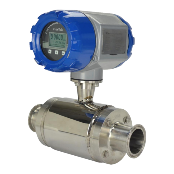
- Page 1 EPD36 Sanitary Electromagnetic Flow Meter Operation Instruction FineTek Co., Ltd. No.16, Tzuchiang St., Tucheng Industrial Park, New Taipei City 23678 Tel: 886-2-22696789 Fax: 886-2-22686682 Website: http://www.fine-tek.com E-mail:info@fine-tek.com 0-EPD36-B4-EK,08/17/2021...
-
Page 2: Table Of Contents
Contents 1. Reading Labels ...................... 1 2. Product Warranty ....................2 2.1 New Product Warranty ..................2 2.2 Repair Warranty ....................2 2.3 Service Network ....................3 3. Product Inspection ....................4 3.1 Check Content ...................... 4 3.2 Safety Inspection....................4 4. - Page 3 13.Inspection before Power-On ................16 14. Parameter Functions ..................17 14.1 Procedure for Menu Setting ................17 14.1.1Functions of the Display Interface ..............17 14.1.2 Button Functions in Parameter Setting Status: ..........17 14.2 Various Parameter Setting Ranges ..............18 14.3 System record illustration ..................
-
Page 4: Reading Labels
1. Reading Labels Thanks for purchasing FineTek’s Product. This operation manual describes the product features, working principles, operation and maintenance methods. It makes the user fully understand how to use the product correctly, so as to prevent dangerous situations such as device damage or operator injury. -
Page 5: Product Warranty
2. Product Warranty 2.1 New Product Warranty We don’t charge for the inspection, part/s and repair for the product of the company that has a defect within 12 months from the delivery date and meets the warranty terms. If the product defect is not due to human error during its transportation, user may change to a new unit from the company within 7 days from delivery date. -
Page 6: Service Network
Township, Minhang District, +86 021 64907260 +86 021 6490 7276 Shanghai City 201109 (China) No. 60 Kaki Bukit Place, FineTek Pte Ltd. +65 6452 6340 +65 6734 1878 #07-06 Eunos Techpark 2 (Singapore Branch) Lobby B, Singapore 415979 Bei den Kämpen 26... -
Page 7: Product Inspection
3. Product Inspection 3.1 Check Content 1 flow meter 1 operation manual 1 product inspection sheet 3.2 Safety Inspection Please check whether the external package is deformed or damaged. Please remember to take a picture for evidence for compensation later. ... -
Page 8: Product Features
5. Product Features The measurement results is not affected by the change of liquid density, viscosity, temperature, pressure and conductivity. There are only two measurement points in the measuring tube without baffle and movable parts, so it won’t cause pressure loss and jam. ... -
Page 9: Working Principles
8. Working Principles The working principle of the electromagnetic unit is based on the Faraday law of electromagnetic induction. When the conductor moves in the magnetic field, it will generate induced EMF on both sides of the conductor in the orthogonal direction of the magnetic field direction and the motion direction. -
Page 10: Technical Performance
JIS B7554-1997 ANSI B16.5 DIN 25 Series 9.2 Basic Parameters and Performance Indicators 9.2.1 Technical Specification Table Item EPD36 Standard type Display LCM 128* 64 pixel backlit type Buttons Tri-button operation RS-485 (Modbus) (Optional support for ZigBee Pro wireless Communication interface... -
Page 11: Recommended Flow Range For Tube Diameters
9.2.2 Recommended Flow Range for Tube Diameters Flow range (m Pipe diameter (mm) Flowing speed 0.1~1.0m/s Flowing speed 1.0~10m/s 0.06~0.64 0.64~6.4 0.17~1.77 1.77~17.7 0.45~4.5 4.5~45.2 0.71~7.1 7.1~71 9.2.3 Lining Material Lining material Main properties Application scope 1. Stable chemical properties, resistance to various acid, alkane, and salt solutions 1. -
Page 12: Appearance And Dimension
10. Appearance and Dimension 10.1 Tri-Clmp Type 10.1.1 Tri-Clamp Connection specification Tri-Clamp Nominal diameter(mm) Lining material Length 258.6 258.6 ϕD External diameter 68.3 81.1 106.3 106.3 ϕC Flange thickness 61.5 61.5 Quantity of screw holes Height of sensor casing 76.3 89.1 114.3 114.3... -
Page 13: Installation
11. Installation The design, test and power supply for the flow meter are based on the related regulations. User must strictly follow the instructions to guarantee the safe operation and normal working of the flow meter. 11.1 Conditions required to guarantee the measurement accuracy of the electromagnetic flow meter: ... -
Page 14: Handling
11.4 Handling The flow meter must be handled with the correct handling method. The safety load and protection action of the handling equipment should meet the related regulations. The transmitter box (for integrated flow meter) or enclosure (for separated flow meter) must not be tied up to handle the flow meter. - Page 15 The flow meter must be free from strong electromagnetic field. The magnetic intensity of the flow meter installation site must be smaller than 400A/m. (It should not be installed near large motors or transformers)。 There should be enough space left surrounding the flow meter for installation and repair. If the measuring pipe vibrates, a support frame should be set up on both sides of the flow meter.
-
Page 16: Notes For Installation On The Pipe
11.6 Notes for Installation on the Pipe When installing the flow meter, one must follow the installation diagrams as shown below. This will ensure the flow meter can guarantee the pipe is always filled with the liquid: (The figures below are only typical cases, which don’t include all feasible installation methods. -
Page 17: Grounding Requirements
11.7 Grounding Requirements The grounding of the electromagnetic flow meter is very important. If the grounding is poor, it won’t work normally. The sensor and transmitter should be equipped with high-quality independent grounding wire (The section area of the copper core is 1.6mm ). -
Page 18: Wiring And Using
12. Wiring and Using 12.1 Wiring 12.1.1 Notes for Wiring For the power line, the 2-core rubber insulated cable is recommended. For AC power supply, L1 should be “Live Wire”. The wiring of all terminal blocks should be clamped with slotted terminal and performed with insulation. -
Page 19: Inspection Before Power-On
13. Inspection before Power-On 1. Check whether the flow meter is damaged during transportation and installation. 2. Check whether the voltage of the power supply is consistent with that specified on the nameplate. 3. Check whether the fuse used is of the correct current value. 4. -
Page 20: Parameter Functions
14. Parameter Functions 14.1 Procedure for Menu Setting ↑ ↑ Parameter Measurement screen Main menu 1 Sub menu 1 ↓ ↓ Parameter Main menu 2 ↓ ↓ Number edit mode Button Parameter Main menu 3 Parameter editing Confirm (Holding) ↑ Move “Left ←... -
Page 21: Various Parameter Setting Ranges
14.2 Various Parameter Setting Ranges Main Menu Sub Menu Unit Default Setting Range Device Tag Num (1.1) Zero Adj.(2.1) Flow Span (1.5) Fast Set (0) The parameter is linking from standard menu Flow Unit (1.4) Low cutoff (2.4) Damping Time (3.1) Pulse Out Unit (3.3) Total Reset (1.9) Main Menu... - Page 22 Main Menu Sub Menu Unit Default Setting Range Damping Time (3.1) second 0~100 Pulse Out Mode (3.2) none Pulse NO Pulse NO, Pulse NC, Frequency 0.001~100(L,gal, m ,g,kg,Ton) Pulse Out Unit (3.3) Unit/pulse 0.1 L L/pulse,gal/pulse, m /pulse,g/pulse, kg/pulse,Ton/pulse Max. Freq. (3.4) 0.001~8K (00.000) Curr.
- Page 23 Main Menu Sub Menu Unit Default Setting Range English,Traditional Chinese, Language(5.1) English Simplified Chinese Tube Status Actual Normal, Empty Resistance Actual System Info.(5.2) kΩ Status Code Actual Act. Flow Speed Actual 0000 0000 ~ FFFF FFFF Normal, Circuit Self-Test(5.3) Cancel Fail ,Excitation Fail, Amb.
-
Page 24: System Record Illustration
14.3 System record illustration Display image illustration ④ ① ② ⑤ ③ ⑥ ⑦ illustration The date when incident occur. Category of the incident. Separated into “System” and “User Set”. Please see details in below chart. The alarm information. The time when incident occur. “OCC”... - Page 25 Category Alarm information Alarm illustration The working temperature has exceed the 01 Over temperature operating temperature of the panel. There is no fluid in the tube or the fluid 02 Empty tube conductivity is less than 5us/cm. Sensor is not correctly connected or there is abnormal on the excitation 03 Sensor disconnection current which will cause sensor the...
-
Page 26: Ordering Information
15. Ordering Information... -
Page 27: Transportation And Storage
16. Transportation and Storage To prevent the flow meter from damage during the transportation, please keep the packaging condition as how it was when it was shipped from the factory before arriving at the installation site. The storage conditions should meet the following: ... -
Page 28: Fault Inspection And Repair
17. Fault Inspection and Repair When fault occurs to the flow meter or it fails to meet the accuracy requirements, please try to fix it by referring to the table below. Fault Inspection Solution The casing of the flow meter is grounded correctly. -
Page 29: Modbus Communication Protocol
18. MODBUS Communication Protocol Address(Hex) Address(Dec) Variable Name Data Type Unit Range Definition Authority Read 0x1000 4096 gt_modbus_slave_fine_tek_id[0] UINT8 "FI" only(Header) Read 0x1001 4097 gt_modbus_slave_fine_tek_id[2] UINT8 "NE" only(Header) Read 0x1002 4098 gt_modbus_slave_fine_tek_id[4] UINT8 "-T" only(Header) Read 0x1003 4099 UINT8 gt_modbus_slave_fine_tek_id[6] "EK"... - Page 30 0x1040 System status Data Type Unit Range Definition Authority 0x1040 4160 PFC_TEMPERATURE_BOARD_NOW-High Read only FLOAT32 PCB temp. 0x1041 4161 PFC_TEMPERATURE_BOARD_NOW-Low Read only 0: Normal 0x1042 4162 PFC_SELF_TEST_TUBE_STATUS UINT16 \Setting\ Information\ Status of pipe Read only 1: Empty 0x1043 4163 pfc_system_status_code_value-High Read only \Setting\ Information\ system status UINT32...
- Page 31 0x1070 Parameter setting- Advanced setting Data Type Unit Range Definition Authority 0x1070 4208 PFC_BASIC_SET_ZERO_ADJ-High Read /Write 0x1071 4209 PFC_BASIC_SET_ZERO_ADJ+1 Read /Write Basic setting/ Zero point FLOAT64 m/s -0.5000~+0.5000 setting 0x1072 4210 PFC_BASIC_SET_ZERO_ADJ+2 Read /Write 0x1073 4211 PFC_BASIC_SET_ZERO_ADJ-Low Read /Write 0x1074 4212 PFC_BASIC_SET_K_FACTOR-High Read /Write 0x1075 4213 PFC_BASIC_SET_K_FACTOR+1 Read /Write...
- Page 32 0x1090 Parameter setting- Output/Input signal setting Data Type Unit Range Definition Authority Output/Input signal 0x1090 4240 PFC_IO_SIGNAL_SET_DAMPING_TIME UINT16 Second 000~+100(Default:3) setting/ Input signal Read /Write average time 0:NO 0x1091 4241 PFC_IO_SIGNAL_SET_PULSE_OUTPUT_MODE UINT16 1:NC Pluse output mode Read /Write 2: Frequency output 0x1092 4242 PFC_IO_SIGNAL_SET_PULSE_OUTPUT_UNIT-High Read /Write 0x1093 4243 PFC_IO_SIGNAL_SET_PULSE_OUTPUT_UNIT+1...
- Page 33 0x10A5 Parameter setting- Alarm setting Data Type Unit Range Definition Authority 0x10A5 4261 PFC_ALARM_SET_MAX_FLOW_RATE-High Read /Write 0x10A6 4262 PFC_ALARM_SET_MAX_FLOW_RATE+1 Read /Write +0.0000 ~ Line FLOAT64 Max. flow rate size(m)^2 *7.85 0x10A7 4263 PFC_ALARM_SET_MAX_FLOW_RATE+2 Read /Write 0x10A8 4264 PFC_ALARM_SET_MAX_FLOW_RATE-Low Read /Write 0x10A9 4265 PFC_ALARM_SET_MIN_FLOW_RATE-High Read /Write 0x10AA 4266 PFC_ALARM_SET_MIN_FLOW_RATE+1...
- Page 34 0x10B9 Parameter setting- System setting Data Type Unit Range Definition Authority 0: English 0x10B9 4281 PFC_SYSTEM_SET_LANGUAGE UINT16 1: Chinese (Traditional ) Language Read /Write 2: Chinese (Simple) PFC_SYSTEM_SET_ANALOGY_INPUT_4MA 0x10BA 4282 _INFO-High Analog setting/ 4 mA FLOAT32 0~9999 Read /Write Value PFC_SYSTEM_SET_ANALOGY_INPUT_4MA 0x10BB 4283...
- Page 35 0x10C9 Parameter setting- Analog Simulation Data Type Unit Range Definition Authority 0:None 1: Flow rate 2: Flow capacity 0x10C9 4297 PFC_SIMULATION_FUNC_STATE UINT16 3: Current output Simulation fuction select Read /Write 4: Frequency output 5: Output1 status 6: Output2 status 0x10CA 4298 PFC_SIMULATION_FLOW_SPEED-High Read /Write 0x10CB 4299 PFC_SIMULATION_FLOW_SPEED+1 Read /Write...
- Page 36 EPD36 衛生接續電磁式流量計 產品操作手冊 桓達科技股份有限公司 23678 新北市土城工業區自強街 16 號 電話:886-2-22696789 傳真:886-2-22686682 網址:http://www.fine-tek.com E-mail:info@fine-tek.com 08-EPD36-B5-CK,08/17/2021...
- Page 37 目 錄 1. 閱讀標示 ........................3 2. 產品保證 ........................4 2.1 新品保固 ......................4 2.2 維修保固 ......................4 2.3 服務網絡 ......................5 3. 產品檢查 ........................5 3.1 物品核對 ......................5 3.2 安全查驗 ......................6 4. 概述 ..........................6 5. 產品特點 ........................7 6.
- Page 38 12. 接線與使用 ......................17 12.1 接線 ......................... 17 13. 送電前的檢查 ......................18 14. 參數功能說明 ......................18 14.1 設定選單流程說明 .................... 18 14.1.1 顯示介面功能 .................... …19 14.1.2 參數設定狀態時的鍵功能 ................19 14.2 各參數設定功能說明 ..................20 14.3 各參數設定範圍說明 ..................28 15. 產品選型 ......................... 30 16.
-
Page 39: 閱讀標示
1. 閱讀標示 感謝您購買本公司桓達科技的產品,此操作說明書是針對產品的特性、動作原理、操作和 維修方式,還有使用注意事項等內容來說明,可讓使用者充分瞭解產品的正確使用方法,避 免發生設備損壞或操作者受傷等危險狀況。 使用本產品前,請完整、仔細的閱讀本操作手冊。 若本操作手冊無法提供您所要的需求時,請與本公司聯絡。 本操作說明書的內容,會依照版本的更新而有所不同,將會上傳於本公司網站上,提供使 用者下載。 請不要自行拆開或維修,這意味著您將失去保固資格。請將產品寄回本公司維修和校準, 或與本公司聯絡。 警告符號說明: 提示危險→表示若操作錯誤會有致命和重大災害的危險。 提示注意→表示若操作錯誤會有一定程度的傷害和設備的損壞。 提示電擊→表示可能會觸電的警告。 提示火災→表示可能會發生火災的警告。 提示禁止→表示禁止的錯誤動作事項。... -
Page 40: 產品保證
2. 產品保證 2.1 新品保固 本公司產品於交貨日算起十二個月內,在符合保固條件之下發生故障,可不收檢測、零 件、維修等費用。 產品運送過程導致新品瑕疵而非人為故障,可於 7 日內向本公司更換。 產品故障需寄回原廠維修時,請將產品整組寄回,勿自行拆卸部品,並且包裝請務必完 善,避免運送損毀,造成更大的損失。 產品保證僅針對正常使用客戶,如有特殊應用、不正常使用及超量使用者,則不在此保證 範圍內。 在以下狀況下發生故障,將不具有保固條件,需酌收收檢測、零件、維修等費用: 產品整機或零件超過保固期限。 未依操作手冊使用或未依說明書上之使用環境,所致之故障毀壞。 產品之毀損係受不可抗力(天災、水災、火災、地震、雷擊、颱風等),人為破壞(刮 傷、摔傷、卡榫斷裂、敲打、破裂、重擊等),人為疏失(使用不合適的電壓、高濕、 進水、汙漬、腐蝕、遺失、未妥善保管等)或其他非正常因素所致者。遭遇天災地變之 不可抗拒之外力的情況下,所造成的故障。 客戶擅自或使第三人安裝、添附、擴充、修改、修復非本公司授權或認可之零件所致 之毀壞。 產品標籤資訊不符或破損不清楚而無法確定產品序號時。 2.2 維修保固 本公司對於產品維修後,針對維修部份提供六個月保固期,在此期間內若同一零組件再發 生相同故障時,即可享有免費維修服務。... -
Page 41: 服務網絡
+886 7-333-6968 +886 7-536-8758 (臺灣) 上海凡宜科技電子 201109 +86 021-64907260 +86 021-6490-7276 有限公司(中國) 上海市閔行區顓橋鎮都會路451號 Finetek Pte Ltd. 37 Kaki Bukit Place, Level 4 Singapore +65 6452-6340 +65 6734-1878 (新加坡分公司) 416215 FineTeK GmbH Bei den Kämpen 26 +49 (0) 4185 8083 0 +49 (0) 4185 8083 80 (德國分公司) -
Page 42: 安全查驗
3.2 安全查驗 拆封前請檢查外包裝有無變形或破損,並拍照存證作為事後補償依據 拆封後請檢查內容物有無變形或破損及一切品質問題,並拍照存證作為事後補據 開箱後請立即核對內容物是否與訂購內容相符,數量是否正確 若有以上異常狀況請於貨到 7 日內連絡本公司(連同照片),否則恕不無償給予補換貨 或維修 4. 概述 本公司電磁流量計,採用穩定性高的線圈激磁方式,其穩定性較傳統的生磁方式高。產品 經過嚴苛的震動和抗雜訊測試後都能很穩定的工作,對於工業現場環境的複雜性有良好的耐受 度,在實際的應用中有著更長的產品壽命。 電磁流量計從開始發展到今天,持續不斷的被改良,常被廣泛的應用到各類的工業流體管道的 監控中,其中包含發電、水處理、食品、醫藥、船舶、染整、半導體製程等不勝枚舉。 由於電磁流量計的原理單純,適用範圍廣,只要適當的選型並與流體性質配合便能良好的應用 在各類的環境之中。... -
Page 43: 產品特點
5. 產品特點 測量時不受液體密度、粘度、溫度、壓力及導電率等變化而影響測量結果 測量管內只有兩個量測點,沒有阻流件及活動件,故不會造成壓力損失及堵塞的情況 可測試導電液體及含微量固體顆粒之流體流量 安裝時所需的直管段僅需流量計上游前 5D 及下游 2D,不需複雜的管路設計 測量的量程比可 1:100,尤其在小流量測量時精度高 具備自我診斷功能,可自我偵測激磁訊號、測量管是否為空管、電極是否汙損 內襯材質為 PFA 最高允許流體溫度可達 150℃ 流量轉換器設定簡單、功能性強 6. 適用範圍 導電率: > 5μS/cm 流體性質:液體、含少量固體顆粒之液體。 應用產業: 發電、水處理、食品、醫藥、船舶、染整、半導體製程 7. 環境條件 環境溫度: -40℃... -
Page 44: 工作原理
8. 工作原理 電磁流量計動作原理是基於法拉第電磁感應定律。當導體在磁場內運動,在與磁場方 向、運動方向相互垂直方向的導體兩端,會有感應電動勢產生。電動勢的大小與導體運動速 度和磁感應強度大小成正比。 在<圖一>中,當導電流體以平均流速 V(m/s) ,通過裝有一對測量電極的一根內徑為 D(m) 的絕緣管子流動時,並且該管子處於一個均勻的磁感應強度為 B(T)的磁場中。那麼,在 這對電極上就會感應出垂直於磁場和流動方向的電動勢(E) 。 由電磁感應定律,E 可寫作(1)式: (V) ....(1) 式中 k 是比例係數。 轉換器 體積流量可以寫作 ) ..(2) ( 由公式(1)和(2)可得到: ....(3) 因此電動勢可表示為: ....(4) 當 B 是個常數時,公式(3)中 <圖一> ,公式(3)改寫為: ....(5) 與電動勢... -
Page 45: 基本參數和性能指標
JIS B2220 JIS B7554-1997 ANSI B16.5 DIN 25 Series 9.2 基本參數和性能指標 9.2.1 產品技術規格表 項目 EPD36 螢幕 LCM 128*64 畫素背光型 按鍵 3 鍵式操作 通訊介面 RS-485 (Modbus)(Optional 支援 ZigBee Pro 無線傳輸) 精確度 ±0.5% of reading@1m/s(0.2% optional) -20 ~ 150℃(PFA 內襯) 介質溫度 環境溫度... - Page 46 9.2.3 內襯材料 內襯材料 主要性能 適應範圍 1. 化學性能穩定,能耐各種酸、鹼、鹽溶液和各 ℃ 種有機溶劑。不耐三氟化氯(ClF3),高溫三氟氟化 1. -20~150 氧,高流速液氧,臭氧的腐蝕。 2. 濃酸、鹼等強腐蝕性介質。 2. 耐磨性能一般。 9.2.4 電極材料 電極材料 耐蝕性能 不鏽鋼(316L) 用於水、污水或無機、有機腐蝕性介質。 9.2.5 外殼防護等級 IP67...
-
Page 47: 外型尺寸
10. 外型尺寸 衛生接續型 10.1 Tri-Clamp 接續規格 Tri-Clamp 公稱通徑(mm) 內襯材質 長度 258.6 258.6 ϕD 外徑 68.3 81.1 106.3 106.3 ϕC 法蘭厚度 61.5 61.5 螺絲孔數量 傳感器高度 76.3 89.1 114.3 114.3 總高度 重量(Kg) -
Page 48: 保證電磁流量計測量精度的必要條件
11.安裝 流量計的設計、試驗和供電均有相關規定,用戶必須嚴格遵守說明,以確保流量計的 安全操作及正常運作。 11.1 保證電磁流量計測量精度的必要條件: 被測液體必須具有導電性 被測液體必須能充滿管道 被測液體必須均勻,以保證避免電導率的不均勻性(會產生嚴重干擾) ,如需動態 加入化學物質,應在流量計下游處加入 電磁流量計系統必須良好接地,尤其在塑膠管道中一定要加裝接地環並實值接地 流量計入口直管段至少 5 倍 D(測量管道內徑) ,出口直管段至少 2 倍 D 在流量計附近應避免強電磁場干擾;避免安裝在大型電機或變壓器等設備附近 11.2 安全措施 為保障人身和設備的安全,須遵守以下事項: 在選擇位置和安裝流量計之前,必須認真閱讀完本說明書有關部分,同時要考慮 流量計、相關設備和機身環境的安全要求 應由具備一定流量計知識的人員進行流量計的安裝和維修 正確安裝流量計感測器及配管,保證密封安全可靠,液體壓力不得超過流量計規 格上所能承受的最高工作壓力 採取適當措施,防止觸電事故 流量計的吊裝設備應符合安全規定 11.3 安裝前的檢查... -
Page 49: 正確安裝
11.4 吊裝 流量計應採用正確吊裝方法進行吊裝,吊裝設備的安全載荷及防護措施應符合有關規定。 禁止在傳送器箱體(一體式流量計)或接線盒(分離型流量計)處用繩拴起吊流量計。 11.5 正確安裝 正確地選擇安裝點和正確安裝流量計都是非常重要的環節,若在安裝環節失誤,輕者影 響測量精度,重者會影響流量計的使用壽命,甚至會損壞流量計。 選擇安裝位置時需特別注意 a. 測量電極的軸線必須近似於水平方向(與水平線夾角一般為 10°以內) 。 b. 測量管道內必須完全充滿液體。 c. 流量計的前方最少要有 5×D(D 為流量計內徑)長度的直管段,後方最少要有 2×D (D 為流量計內徑)長度的直管段。 d. 流體的流動方向和流量計的箭頭方向一致。 e. 請避免在管道內出現真空現象,會損壞流量計的內襯,。 f. 在流量計附近應無強電磁場,流量計安裝場所的磁場強度應小於 400A/m (避免安裝在大型電機或變壓器等設備附近) 。 g. 在流量計附近應有充裕的空間,以便安裝和維護。 h. 若測量管道有振動,在流量計的兩邊應有固定的支座。... - Page 50 i. 測量不同介質的混合液時,混合點與流量計之間的距離最少要有 30×D(D 為流量計 內徑長度) 。 j. 為方便今後流量計的清洗和維護,應安裝旁通管道。 k. 安裝 PTFE 內襯的流量計時,連接兩法蘭的螺栓應注意均勻擰緊,否則容易壓壞 PTFE 內襯,盡可能使用扭力板手。 l. 流量計應避免強烈振動和過大的溫度變化,同時要防止腐蝕性液體的對流量計造成 損害。 m. 如果安裝地點易受陽光曝曬,應增加遮陽設施。 n. 安裝感測器時,應盡可能的使測量管與製程管道位於同一個軸線上。 對 DN50 及以下公稱通徑的感測器,其軸線偏離不超過 2mm。DN65~DN150 其軸 線偏離不超過 3mm,≥DN200 其軸線偏離不超過 4mm。 o. 法蘭之間加裝的墊片,應有良好的耐腐蝕性能,該墊圈不得伸入管道內部,阻礙流體 流動。 p. 緊固流量計螺栓、螺母,其螺紋應完整無損,潤滑良好。應依據法蘭尺寸、力矩大小 採用力矩板手緊固螺栓。 q. 在感測器鄰近管道進行焊接或火焰切割時,要採用隔離措施,防止襯裏受熱,且必須 確認流量計未通電運行,防止損壞流量計。...
-
Page 51: 管道上安裝注意事項
11.6 管道上安裝注意事項 流量計安裝時,必須遵守以下安裝示意圖例,以確保流量計可以保證液體永遠 充滿管道:(以下圖例僅為典型說明,並未包含全部可行的安裝方式,使用者應依實 際工況進行安裝位置判斷。) 序號 圖例 說明 應安裝在水平管道較低處和 垂直向上處。 避免安裝在管道的最高點和 垂直向下處。 應安裝在管道的上升處。 若管道落差超過 5m,在傳感 排氣閥 器的下游安裝排氣閥 傳感器的下游應有一定的背 壓。 應在傳感器的下游安裝控制 閥和切斷閥,而不應安裝在 傳感器上游。 傳感器絕對不能安裝在幫浦 的進口處,安裝在幫浦的出 口處。... -
Page 52: 接地要求
11.7 接地要求 電磁流量計的接地是非常重要的,若接地不良,無法正常工作,感測器和傳送 器部分應有良好的單獨接地線(銅芯截面積為 1.6mm ) ,接地電阻<10Ω。 圖例 說明 接地環 若與感測器連接的管道是絕 緣性的,則需用接地環 應選擇其材質和電極的材質 一樣,避免被液體。 若被測介質是磨損性的,應 選擇帶頸接地環。 接地方式 流量計在金屬管道上的安 裝,金屬管道内壁没有絕緣 塗層。 流量計在塑膠或内壁有絕緣 塗料、油漆、内襯等管道上 安裝時,應在傳感器的兩端 安裝接地環。 流量計在陰極保護管道上安 裝,防護电解腐蝕的管道一 般在其壁和外壁是絕缘的, 安裝時需注意接地環和管道 上的法蘭應絕緣。 11.8 改變傳送器盒的方向 傳送器盒可以根據需要作四個不同方向的轉變。 a. 一體型流量計的傳送器盒方向的改變 ... -
Page 53: 接線與使用
12. 接線與使用 12.1 接線 12.1.1 接線注意事項 電源線建議選用二芯絕緣橡皮電纜線,線材外徑應大於 10mm。 當為交流供電時,L1 應接“火線” 一般 24VDC 電源供電的情況下,電纜線的電阻應不大於 10Ω。 所有的端子台接線應夾一字端子,並作好絕緣;應避免電線直接伸入端子台。 電流輸出端子出線電纜總阻抗不得大於規格所標稱的阻抗。 脈波或頻率輸出一般為 NPN 晶體輸出,需外接電源。 12.1.2 打開背後外殼蓋,可看見如下圖所示接線端子 DC 24V 數位輸出 1 RS-485 通訊 數位輸入 DO1- DO1+ 電壓脈波輸出 4-20mA 輸出 DC24V... -
Page 54: 送電前的檢查
13. 送電前的檢查 1. 流量計在運輸和安裝中有無損傷 2. 使用電源電壓同銘牌電壓是否相符 3. 使用正確流量值的保險絲 4. 流量計正確接地 5. 打開管道閥門使液體充滿管線系統,應注意排除洩漏和系統內的殘留氣體 6. 接通流量計電源,通電預熱 10 分鐘即可正常工作 14. 參數功能說明 14.1 設定選單流程說明 ↑ ↑ 主選項 量測劃面 次選項1 參數1 ↓ ↓ 主選項 參數2 ↓ ↓ 主選項 參數3 參數編輯 ↑ 按鍵 數字編輯模式 3秒 確認鍵(長按) ←... -
Page 55: 顯示介面功能
14.1.1 顯示介面功能 0.0000 瞬間流率 +1274205.8 Liter 累績總量 H 00.00 Bar 量程百分比 管內壓力 操作按鍵 14.1.2 參數設定狀態時的鍵功能 參數設定頁面 按鍵 量測主劃面 選單模式 數字編輯模式 清單編輯模式 Read Only 進入選單 進入次選單 確認鍵(長按) 確認鍵(長按) ← 回上層 回上層 回上層 "左"位移鍵 ↑ 次選單項目【下】 數字:"加"鍵 選項:下翻頁 取消 ENT+ <... -
Page 56: 各參數設定功能說明
14.2 各參數設定功能說明 主選項 次選項 說明 單位 出廠值 設定值範圍 功能描述 裝置位號 (1.1) 流量零點調整 (2.1) 流率滿量程 (1.5) 瞬時流率單位 快速設定(0) 此區參數是從標準選單中取出之捷徑 (1.4) 低流量屏避 (2.4) 輸入訊號平均時間 (3.1) 脈波單位設定 (3.3) 總量重置設定 (1.9) - Page 57 主選項 次選項 說明 單位 出廠值 設定值範圍 功能描述 裝置位號 客戶端工廠管理用 tag none 00001 00001~65535 (1.1) number 量測液體類型 水 水(Water) 設定量測液體類型種類 (1.2) 10~100 10,15,25,32,40,50,65,80,100 流量計口徑 設定流量計公稱通徑, mm(1.3.1) actual 可計算流量量程 (1.3) 125~500 125,150,200,250,300,350,40 mm(1.3.2) 0,450,500 L/(s,min,h), m /(s,min,h), gal/(s,min,h), kg(s,min,h), Ton(s,min,h) (若選重量單位,流量自動和 瞬時流率單位 密度相乘) 瞬時流量自動以此設定...
- Page 58 主選項 次選項 說明 單位 出廠值 設定值範圍 功能描述 AUTO 流量零點調整 在滿管無流量時的零點 Actual -0.5000~+0.5000 流量補償 (2.1) MANUAL 流量系數 K 流量傳感器特徵參數, none 1.000 0.000~3.000 真實值 = 測量值 x k (2.2) 密度 質量流量=體積流量*密度 (2.3) g/cm 1.0000 0.0001~9.9999 進階設定 當管路內有微流或振動 低流量屏避 時,找低流顯示屏避 (2.4) 0.00~100.00 (判斷流率大於該值才顯 示並累積) 順向總量起始值...
- Page 59 主選項 次選項 說明 單位 出廠值 設定值範圍 功能描述 輸入訊號平均時間 將實際流量做平均值輸出 second(s) 3 0~100 (3.1) Pulse 輸出接點的初始狀 態,或用頻率來表示流率 脈波輸出模式 Pulse NO, Pulse NC, (如果選頻率,依流率表 none Pulse NO (3.2) Frequency 示),Pulse No,Nc 為總量 輸出的高低電位狀態 0.001~100(L,gal,m ,g,kg,Ton) 脈波單位設定 可設定每個 pulse 所代表 Unit/pulse 0.1 L L/pulse,gal/pulse,m /pulse,g/p 的流量...
- Page 60 主選項 次選項 說明 單位 出廠值 設定值範圍 功能描述 流率上限 瞬時流率 設定流率超過此設定 該口徑最大值 0~±至流率上限值(000.00)- 單位 時,則被觸發報警 (4.1) 流率下限 瞬時流率 設定流率低於此設定 該口徑最小值 0~±至流率上限值(000.00)- 單位 時,則被觸發報警 (4.2) 空管檢測 當電導率低到某一程度 Disable Disable,Enable 即判斷為空管狀態 (4.3) 輸出 1 功能 None,流量上限警報,流量下限 流量上限警報 選擇輸出 1 接點的功能 警報,空管警報,系統異常 (4.4) 警報設定(4) 輸出...
- Page 61 主選項 次選項 說明 單位 出廠值 設定值範圍 功能描述 系統語言 English, 繁中, 简中 系統顯示語言 English (5.1) 檢測目前量測管內液體是否 測量管狀態 正常/空管 Actual 溢過兩電極測量點 目前流速 測量目前流體速度的真實值 Actual 系統資訊 (5.2) kΩ 液體阻抗 測量目前流體電阻值真實值 Actual 系統狀態碼 顯示目前系統狀態代碼 Actual 0000 0000 ~ FFFF FFFF 正常:系統自我檢測無發現 任何異常現象 電路異常:板溫過高/過 系統設定 低、I/O 失效、無法檢知訊...
- Page 62 Modbus 1~255 ID(2.13.1) BaudRate 1200,2400,4800,9600,19200,38 9600 (2.13.2) 400,57600 Modbus Data 通訊 基本通訊設定 bit(2.13.3) (5.5) Parity none none,odd,even (2.13.4) Stop bit(2.13.5) 恢復出廠設 定值 取消 取消,確認(Cancel, Accept ) (5.6) 市電頻率 選擇接入之市電頻率 50,60 (5.7) LCM 亮度 選擇顯示對比亮度 15~40 (5.8) 使用者密碼 使用者密碼 選單密碼 (5.9.1) 00000 0~99999 管理者密碼...
- Page 63 主選項 次選項 說明 單位 出廠值 設定值範圍 功能描述 模擬流速,使系統做出 流速模擬 相應的反應。(選單無 -10 ~ 10 (6.1) 返回計時) 模擬流量,使系統做出 流量模擬 流量單位 相應的反應。(選單無 0~該口徑最大值 (6.2) 返回計時) 僅電流輸出 port 做出 電流輸出模擬 反應。(選單無返回計 訊號模擬 3.6~22 (6.3) 時) pulse port 做出相應頻 頻率輸出模擬 率輸出。(選單無返回 (離開此選單 Hz(pulse/秒) 2 2~8000 (6.4) 後回到正常...
-
Page 64: 各參數設定範圍說明
14.3 各參數設定範圍說明 顯示畫面說明 ④ ① ② ⑤ ③ ⑥ ⑦ 項次 欄位說明 事件發生日期。 事件發生分類,區分為『系統類』與『使用者設定類』 ,詳見下表。 實際發生的告警訊息。 事件發生時間。 事件觸發。 『OCC』代表該事件發生。 事件觸發。 『CLR』代表該事件已被解除。 顯示當下所在頁碼。... - Page 65 分類 告警訊息 告警說明 #01 環境溫度過高 超出電路正常工作溫度範圍。 Over temperature #02 量測管空管 量測管內沒有液體或液體導電度低於 Empty tube 5us/cm 傳感器未正確連接或勵磁電流異常,無法 #03 傳感器未正確連接 正常檢知流量。 Sensor disconnection System #04 電路異常 I/O 失效、無法檢知訊號。 Circuit abnormal #05 進入模擬狀態 流量計被設定進入模擬測試功能。 Simulation mode #06 電極汙損 電極嚴重被覆蓋非導電性物質。 Electrode coating #21 超過設定最高瞬時流量 目前瞬間流量高於所設定最高允許流量。 Over flow rate #22 低於設定最低瞬時流量...
-
Page 66: 產品選型
15. 產品選型... -
Page 67: 運輸與貯存
16. 運輸與貯存 為防止流量計在轉運時受到損傷,在到達安裝現場以前,請保持製造廠發運時的包裝 狀態。在貯存過程中,貯存地點應具備下列條件: 需做適當防雨及防潮 盡可能的減少運送時的振動並避免撞擊 溫度範圍-20~70℃ 溼度低於 80% 貯存使用過的感測器,須先清除附著於襯裏和電極表面上的被測介質,避免長期曝露 在空氣中而氧化 露天貯存,流量計性能可能會受影響... -
Page 68: 故障檢查與維修
17. 故障檢查與維修 如果流量計出現故障與無法達到精度要求,請嘗試利用下表說明進行排除 現象 檢查 處理方法 無法達到精度 流量計零點是否漂移 流量計外殼正確接 地。 塑膠管路需檢查接地 環是否腐蝕 進行零點校正。請參 閱選單第 7 項。 管道是否充滿液體 改變安裝位置,使流 體充滿管道 流量計是否在接近流率範圍上限或 降低或提高流速,使 下限值工作 流速介於 1m/s ~10m/s 之間。 檢查量程設定是否正確 確保流量計量程和接 收流量計訊號設備設 定義的量程是一致 的。... -
Page 69: Modbus 通訊協定
18. MODBUS 通訊協定 EPD36 Measuring Ststem ModBus Communication Address (Auto ID)List 位置 位置 變數名稱 資料類型 單位 範圍 定義 權限 (十六進制) (十進制) Read 0x1000 4096 gt_modbus_slave_fine_tek_id[0] UINT8 "FI" only(Header) Read 0x1001 4097 gt_modbus_slave_fine_tek_id[2] UINT8 "NE" only(Header) Read 0x1002 4098 gt_modbus_slave_fine_tek_id[4] UINT8 "-T"... - Page 70 PFC_FlowTotal_FRAM_REV 0x1014 4116 Read only _VAL-High 目前總逆向 0x1015 4117 PFC_FlowTotal_FRAM_REV_VAL+1 Read only FLOAT64 累積流量 0x1016 4118 PFC_FlowTotal_FRAM_REV_VAL+2 Read only PFC_FlowTotal_FRAM_REV_VAL- 0x1017 4119 Read only PFC_FlowTotal_FRAM_BI_DIR 0x1018 4120 Read only _VAL-High PFC_FlowTotal_FRAM_BI_DIR 0x1019 4121 Read only 目前總雙向 _VAL+1 FLOAT64 累積流量 PFC_FlowTotal_FRAM_BI_DIR 0x101A 4122 Read only...
- Page 71 \系統設定\ 0x1028 4136 gb_pfc_liquid_resistance-High Read only KΩ 系統資訊\ FLOAT32 0x1029 4137 gb_pfc_liquid_resistance-Low Read only 液體阻抗值 目前總順向 0x102A 4138 PFC_FlowTotal_FWD_VAL-Low Read only UINT32 Liter 累積流量 0x102B 4139 PFC_FlowTotal_FWD_VAL-High Read only 目前總逆向 0x102C 4140 PFC_FlowTotal_REV_VAL-Low Read only UINT32 Liter 累積流量 0x102D 4141 PFC_FlowTotal_REV_VAL-High Read only 目前總雙向...
- Page 72 參數設定-基楚設定 0x1055 位置 位置 變數名稱 資料類型 單位 範圍 定義 權限 (十六進制) (十進制) 基礎設定/裝 PFC_BASIC_SET_DEVICE_TAG 00001~65535 0x1055 4181 UINT16 Read /Write 置位號 _NUM (Default:1) 設定量測液 0:水 1:none 0x1056 4182 PFC_BASIC_SET_MEASURE_TYPE Read /Write 體種類 10~10 設定管徑除以 1000 ; 例 0x1057 4183 PFC_BASIC_SET_TUBE_SIZE-High 基礎設定/流...
- Page 73 參數設定-進階設定 0x1070 位置 位置 變數名稱 資料類型 單位 範圍 定義 權限 (十六進制) (十進制) 0x1070 4208 PFC_BASIC_SET_ZERO_ADJ-High Read /Write 基礎設定/流 0x1071 4209 PFC_BASIC_SET_ZERO_ADJ+1 Read /Write -0.5000~ FLOAT64 量零點調整 +0.5000 0x1072 4210 PFC_BASIC_SET_ZERO_ADJ+2 Read /Write 0x1073 4211 PFC_BASIC_SET_ZERO_ADJ-Low Read /Write 0x1074 4212 PFC_BASIC_SET_K_FACTOR-High Read /Write +0.0000~ 基礎設定/流...
- Page 74 PFC_ADVANCED_SET_FWD_TOTAL 0x1080 4224 Read /Write _INIT-High PFC_ADVANCED_SET_FWD_TOTAL 進階設定/順 0x1081 4225 Read /Write _INIT+1 向總量起始 FLOAT64 0~99999 PFC_ADVANCED_SET_FWD_TOTAL 值 0x1082 4226 Read /Write _INIT+2 PFC_ADVANCED_SET_FWD_TOTAL 0x1083 4227 Read /Write _INIT-Low PFC_ADVANCED_SET_REV_TOTAL 0x1084 4228 Read /Write _INIT-High PFC_ADVANCED_SET_REV_TOTAL 進階設定/反 0x1085 4229 Read /Write _INIT+1 向總量起始...
- Page 75 PFC_IO_SIGNAL_SET_MAX_FREQ- 0x1096 4246 Read /Write High 輸出入訊號 0x1097 4247 Read /Write +0.0010~10.000 設定/頻率設 0x1098 4248 Read /Write FLOAT64 (Default:2.0) 定 PFC_IO_SIGNAL_SET_MAX_FREQ- 0x1099 4249 Read /Write 輸出入訊號 PFC_IO_SIGNAL_SET_OUTPUT_CU 0: 4-20mA 設定/電流輸 0x109A 4250 UINT16 Read /Write RR_MODE 1: 0-20mA 出模式設定 輸出入訊號 -000.0~ PFC_IO_SIGNAL_SET_4MA_FINE_T 設定/電流輸...
- Page 76 參數設定-警報設定 0x10A5 位置 位置 變數名稱 資料類型 單位 範圍 定義 權限 (十六進制) (十進制) PFC_ALARM_SET_MAX_FLOW_RAT 0x10A5 4261 Read /Write E-High PFC_ALARM_SET_MAX_FLOW_RAT 0x10A6 4262 Read /Write +0.0000 ~ 口徑(m)^2 警報設定/流 FLOAT64 率上限 PFC_ALARM_SET_MAX_FLOW_RAT *7.85 0x10A7 4263 Read /Write PFC_ALARM_SET_MAX_FLOW_RAT 0x10A8 4264 Read /Write E-Low PFC_ALARM_SET_MIN_FLOW_RAT 0x10A9...
- Page 77 0:無 警報設定/警 0x10B2 4274 PFC_ALARM_SET_CURR_FUNC UINT16 1:空管警報 Read /Write 報電流功能 2:系統異常 0:3.6 警報設定/警 PFC_ALARM_SET_ALARM_CURR_V 1:3.8 0x10B3 4275 UINT16 Read /Write 報電流設定 2:20.5 3:22 參數設定-系統設定 0x10B9 位置 位置 變數名稱 資料類型 單位 範圍 定義 權限 (十六進制) (十進制) 0:英文 系統設定/系 1:繁中 0x10B9 4281 PFC_SYSTEM_SET_LANGUAGE UINT16 Read /Write...
- Page 78 系統設定/類 比輸入設定/ PFC_SYSTEM_SET_ANALOGY_INP 0x10BF 4287 UINT16 Read /Write 顯示小數點 UT_DOT 位數 系統設定 /MODBUS 通 PFC_IO_SIGNAL_SET_MODBUS_CO 0x10C0 4288 UINT16 0 ~ 255 Read /Write 訊/Modbus MM_ID 1200 :1200bps PFC_IO_SIGNAL_SET_MODBUS_CO 2400 :2400bps 0x10C1 4289 MM_BAUDRATE-High 系統設定 4800 :4800bps /MODBUS 通 UINT32 9600 :9600bps Read /Write 訊/BaudRate...
- Page 79 參數設定-訊號模擬 x10C9 位置 位置 變數名稱 資料類型 單位 範圍 定義 權限 (十六進制) (十進制) 0:None 1:流速模擬 2:流量模擬 訊號模擬功 0x10C9 4297 PFC_SIMULATION_FUNC_STATE UINT16 3:電流輸出模擬 Read /Write 能選擇 4:頻率輸出模擬 5:輸出接點 1 狀態模擬 6:輸出接點 2 狀態模擬 PFC_SIMULATION_FLOW_SPEED- 0x10CA 4298 Read /Write High 0x10CB 4299 PFC_SIMULATION_FLOW_SPEED+1 Read /Write 訊號模擬/流...
- Page 80 0x10DE 系統特殊設定 位置 位置 變數名稱 資料類型 單位 範圍 定義 權限 (十六進制) (十進制) 寫入 USER 0:無 PFC_SAVE_SYSTEM_VAR_TO_EEP 0x10DE 4318 UINT16 Read /Write 1:寫入 EEPROM 寫入 0:無 FACTORY 0x10DF 4319 PFC_ENG_MODE_SAVE_SETTING UINT16 Read /Write 設定 1:寫入 EEPROM 自動依據頻 0:無 率與管徑設 0x10E0 4320 pfc_auto_set_excition_freq_flag UINT16 Read /Write...
Need help?
Do you have a question about the EPD36 and is the answer not in the manual?
Questions and answers