Table of Contents
Advertisement
Quick Links
Advertisement
Table of Contents

Related Manuals for FineTek EPR5


Summary of Contents for FineTek EPR5
- Page 1 EPR5 Paddle Wheel Flow Meter Operation Manual FineTek Co.,Ltd. No.16, Tzuchiang St., Tucheng Industrial Park, New Taipei City 23678 Tel:886-2-22696789 Fax:886-2-22686682 Website:http://www.fine-tek.com E-mail:info@fine-tek.com 08-EPR5-B0-CM,07/20/2023...
-
Page 2: Table Of Contents
Table Of Contents 1. Operation manual use .................... 1 2. Product warranty ....................2 2.1 New product warranty ..................2 2.2 Repair warranty ....................2 2.3 Service Network ..................... 3 3. Product description ....................4 3.1 Data label ....................... 4 3.3 Product introduction .................. - Page 3 6.4.3 Simulate Analog ..................26 6.4.4 Simulate Frequency .................. 26 6.4.5 Connection Set ..................27 6.5 System Settings ................... 27 6.5.1 System Language ..................27 6.5.2 Restore Default Settings ................28 6.5.3 Backlighting Settings ................28 6.5.4 LCD Contrast .................... 28 6.5 Product Information ..................
-
Page 4: Operation Manual Use
1. Operation manual use ➢ Thank you for purchasing this FineTek product. This operation manual describes the product features, operating principle, operation and maintenance methods, as well as precautionary measures that should be taken during the installation, operation or maintenance of this product. This manual is designed to prevent dangerous situations that can result in damage to the product or injury to an installer or operator. -
Page 5: Product Warranty
2. Product warranty 2.1 New product warranty ➢ Each FineTek EPR1 series paddlewheel flowmeter is backed by 1-year limited warranty. Should you experience a problem with one of our products deemed by our factory to be a product failure covered by our warranty, for a period of 1-yearfrom the delivery date we will repair the unit at our factory or provide you with a replacement unit or sub-assembly at our discretion. -
Page 6: Service Network
Aplus FineTek 355 S. Lemon Ave, Suite 1 909 598 2488 1 909 598 3188 D, Walnut, CA 91789 (Sensor Inc.) FineTek Pte Ltd. 37 Kaki Bukit Place, Level 4 (Singapore +65 6452 6340 +65 6734 1878 Singapore 416215 Branch) Bei den Kämpen 26... -
Page 7: Product Description
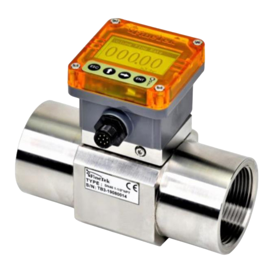
3. Product description 3.1 Data label The data label includes the following information: product model type, power supply voltage, output type, operation temperature/pressure and other specifications. 3.2 Contents of factory shipping carton Verify and inspect the contents you have received to ensure it is what you ordered/requested. A. -
Page 8: Product Features
3.5 Product features Microprocessor-controlled, with complete functions that are easy to operate. Analog signal 4-20mA current output or 0-5V voltage output With communication interface RS485. Analog output range increased by 10%: 4-21.6mA. Simulation test output: 0-24mA. Pulse wave output: 2 sets of NPN transistor output. Simulation frequency output: 0-300Hz. - Page 9 3.6 Types & specifications PVCPipe material & PP Blade Model Type Specification With display type Without display type Applicable pipe DN15、DN20、DN25、DN40、DN50 diameter Pipe material Flow rate range 0.3~10m/s Under standard K Factor ±3% F.S. (Flow velocity 6~10m/s reach Accuracy ±0.5%) Repeatability ±0.4% Measurement...
- Page 10 SUS Pipe material & PVDF Blade Model Type Specification With display type Without display type Applicable pipe DN20、DN25、DN40、DN50 diameter SUS304、SUS316、SUS316L Pipe material 0.3~10 m/s Flow rate range Under standard K Factor ±3% F.S. (Flow velocity 6~10m/s reach Accuracy ±0.5%) ±0.4% Repeatability Magnetic sensing Measurement principle...
- Page 11 SUS Pipe material & SUS316 Blade Model Type With display type Specification Applicable pipe DN25、DN40 diameter SUS304、SUS316、SUS316L Pipe material 0.5~8 m/s Flow rate range Under standard K Factor ±3% F.S. Accuracy ±0.4% Repeatability Magnetic sensing Measurement principle 300 cSt,max. Viscosity range Impurity range Must be nonmagnetic, 1%,max.(Size of particles 0.5mm max.) -15˚C ~100˚C (5˚F ~212˚F)
-
Page 12: Dimensions
4. Dimensions With display Without display Paddl... - Page 13 With Display (Engineering Plastics) Diameter-DN Pipe standards A (mm) (mm) (mm) (mm) (mm) (mm) (mm) DIN/ISO ASTM 21.3 79.1 18.4 DIN/ISO ASTM 26.7 76.3 26.45 CNS.4053-1 DIN/ISO 32.00 ASTM 159.00 115.00 109.00 33.40 58.00 32.55 DIN/ISO 50.00 ASTM 189.00 125.00 119.00 48.30 83.00...
-
Page 14: Without Display (Engineering Plastics)
Without Display (Engineering Plastics) Diameter-DN Pipe standards (mm) (mm) (mm) (mm) (mm) (mm) (mm) DIN/ISO ASTM 21.3 48.4 18.4 DIN/ISO ASTM 26.7 54.8 26.45 CNS.4053-1 DIN/ISO 32.00 ASTM 159.00 115.00 109.00 33.40 58.00 55.20 32.55 DIN/ISO 50.00 ASTM 189.00 125.00 119.00 48.30 83.00... -
Page 15: T-Fitting (Engineering Plastics)
4.3 T-fitting (Engineering Plastics) Diameter-DN Pipe standards (mm) (mm) (mm) (mm) (mm) (mm) DIN/ISO ASTM 21.3 18.4 DIN/ISO ASTM 26.7 26.45 CNS.4053-1 DIN/ISO 32.00 ASTM 159.00 115.00 109.00 33.40 58.00 32.55 DIN/ISO 50.00 ASTM 189.00 125.00 119.00 48.30 83.00 48.70 DIN/ISO ASTM 60.3... -
Page 16: Technical Parameter
4.4 Technical Parameter Selecting Flow And Pipe Diameter ◼ Plastic Blade Flow Range (m Pipe diameter Material Flow velocity 0.3m/s (min) Flow velocity 10m/s (max) (mm) 0.19 6.36 0.34 11.31 PVC Pipe material & 0.53 17.67 PP Blade 1.35 45.23 2.12 70.68 0.34... - Page 17 Without Display K Factor (Pulse/Liter) Connection & Material Standard Type DN15 DN20 DN25 DN40 DN50 60.5 11.05 DIN / ISO 105.8 35.4 6.84 60.5 35.4 11.05 6.84 ASTM 105.8 PVC Pipe material & PP Blade 60.5 35.4 11.05 6.84 105.8 60.5 6.84 CNS 4053-1...
-
Page 18: Assembly Instructions
4.5 Assembly Instructions With Display 1. Flow meter T-fitting. 2. Install the O-ring into the sealing groove and let it expand naturally. Pass the film seat, facing downward, through the hole and the O-ring. Install the screw X4; fasten them evenly and flatly. *Locking torque: Plastic blade = 8~10kgf-cm (0.784~0.98N.m) SUS blade = 10~12kgf-cm (0.98~1.176N.m) -
Page 19: Troubleshooting
4.6 Troubleshooting Error Inspection Solution Display Type: Please remove the one screws on the side of Fig. 6 above; then please counterclockwise remove the display of Fig. 5, and then loosen the four screws of Fig. 4 to clean The pipe has fluidic Please check if the the body blade of Fig. - Page 20 4.7 Mounting location ◼ The straight pipe must be long enough on the upstream side and downstream side where the flow meter is installed. This can obtain an evenly distributed and stable flow field so as to guarantee the measuring accuracy. When installing the flow meter, please choose optimal distance based on the pipe dimension and field environment.
- Page 21 ◼ The flow meter can be installed on a horizontal or vertical pipe, but the requirements below must be followed: 1. The flow meter must be in horizontal or vertical pipe. 2. Ensure the flow meter to keep a full pipe. 3.
-
Page 22: Wiring Instructions
Wiring instructions 5.1 Safety Ensure that power to the paddlewheel flowmeter is disconnected so wiring is performed only in power off status. Check to make sure that the power supply meets the power supply voltage requirement specifications of the paddlewheel flowmeter. If it is possible that the input power voltage might exceed the paddlewheel flowmeter specification voltage please install an overvoltage protection device to protect the paddlewheel flowmeter. -
Page 23: Without Display Connector
5.3 With Display Wiring 5.4 Without Display Connector WITHOUT DISPLAY The colors of cables are defined as shown in the table: Cable No. Functional position Wire color Power input DC 10~32V + Brow Power input DC 0 V - Blue Analog output 4~20mA + Yellow or analog output 0~5V +... -
Page 24: Display Module Adjustment And Setting
6. Display Module Adjustment and Setting 6.1 Button Operations Button Function Return to the previous menu Move up the cursor/Set parameter values Move down the cursor/Select the numbers for the parameter value Enter the selected item/Confirm the operation Enter the Main Menu (Long Press) ○OUT Red light ON indicates alarm... -
Page 25: Flow Rate Unit
6.3 Measuring Set Measuring Set:Set measurement parameters such as unit, flow coefficient K, pipe diameter, filter settings, etc. To enter the main menu from the measurement screen, press and hold. 6.3.1 Flow Rate Unit The measuring setting value can be in the unit of L/minutes, L/hour, m3/minute, m3/hour, gal/minute, gal/hour, kg/minute, kg/hour, ton/minute, and ton/hour. -
Page 26: Pipe Diameter
6.3.4 Pipe Diameter 、 According to the pipe diameter and size, use the keys to switch options; press key to confirm. 6.3.5 Filter Set 、 The flow rate and analog output reaction time can be adjusted with the keys. The parameter values can be confirmed by pressing the key. -
Page 27: Output Signal Settings
6.4 Output Signal Settings Output Signal Set:You can set the pulse output mode (Pulse Out2), the current output type, the analog and analog output parameters, the analog frequency output parameters, the connection setting and speed, etc. 6.4.1 Pulse Out Mode The pulse output mode can be selected from the following three options: 1. -
Page 28: Flow Rate Alarm
6.4.1.3 Flow Rate Alarm 「Flow rate alarm output」→ Set the alarm flow rate value. 「Flow rate alarm (Hysteresis)」→ Set the flow rate hysteresis value. 6.4.1.4 Alarm Status High flow rate alarm: when the measured value is higher than the “flow rate alarm set value”, it changes from High (lower left picture ○... -
Page 29: Analog Output Setting
6.4.2 Analog Output Setting Press to enter the current type in the current output setting. There are 2 kinds of current outputs to choose from, 20mA~4mA, 4~20mA. Press the key to store after completion. ※ Only analog output 4~20mA has this setting. RS-485 and 0~5V do not. In the current output setting, press to enter the upper or lower current limits, and 、... -
Page 30: Connection Set
6.4.5 Connection Set When connecting to a computer, you must have the same address as the local device to connect successfully. The default value is 001. 、 The parameter values can be adjusted by the keys. Press the key to confirm. -
Page 31: Restore Default Settings
6.5.2 Restore Default Settings Press button to confirm the selection. All will be reset to the factory settings. 6.5.3 Backlighting Settings Select the backlighting status based on user’s habits, and press button to save. 6.5.4 LCD Contrast buttons to increase/decrease the contrast, and press button to save. -
Page 32: Settings
7. Settings Function Description Flow Rate Unit (Please refer to 6.3.1) Set the unit of volume flow rate. Flow Total Unit (Please refer to 6.3.2) Set the cumulative quantity unit. Set K factor of flow (0~999.99)。 K Factor (Please refer to 6.3.3) Pipe Diameter (Please refer to 6.3.4) Select pipe diameter. -
Page 33: Digital Communication Protocol
8. Digital Communication Protocol 8.1 Communication Protocol Table Address Name Types Definition default Range Unit Reference (Dec) Display flow Read 4128 FLOAT32 0~11 speed Display flow rate Read 4130 FLOAT32 0~19.44 Display Read 4132 FLOAT32 0~275 frequency value Display output Read 4136 FLOAT32... - Page 34 Simulate 4224 FLOAT32 Read/Write 0~300 frequency value Analog output 4226 FLOAT32 Read/Write 0~24/0~2500 mA/2*mV value Analog output (Please refer 4228 UINT16 Read/Write 0,1,2,3 setting to 8.1.11) Analog output 4230 UINT16 Read/Write filter switch (Please refer Language 4231 UINT16 Read/Write to 8.1.6) Background (Please refer 4233...
-
Page 35: Volumetric Flow Rate Per Unit: Status Table
8.1.1 Volumetric Flow Rate per Unit: Status Table Flow rate unit Flow unit L / min Flow unit L / hr Flow unit m / min Flow unit m / hr default Flow unit gal / min Flow unit gal / hr Flow unit kg / min Flow unit kg / hr Flow unit ton / min... -
Page 36: Internal Eeprom Saving Table
8.1.4 Internal EEPROM saving table Save system var to EEPROM Save system var to EEPROM Save system var to EEPROM Save setting 8.1.5 Internal parameter saving status table Save calibration setting Save calibration setting Save calibration setting Save setting 8.1.6 Language settings status table Language Language English... -
Page 37: Pulse Output Mode: Status Table
8.1.9 Reset Total table Cumulative Reset Setting Reset Total Reset Total Reset 8.1.10 Pulse output mode: status table Pulse Output: 2 Types Pulse Out Mode Pulse Output Flow Unit: Liter/Pulse Pulse Output Flow Unit: Pulse Out Mode Gal/Pulse Pulse Output Flow Unit: Pulse Out Mode m 3 /Pulse Alarm output cumulative value,...
Need help?
Do you have a question about the EPR5 and is the answer not in the manual?
Questions and answers