Table of Contents
Advertisement
Quick Links
Advertisement
Table of Contents

Related Manuals for FineTek EPR1 Series


Summary of Contents for FineTek EPR1 Series
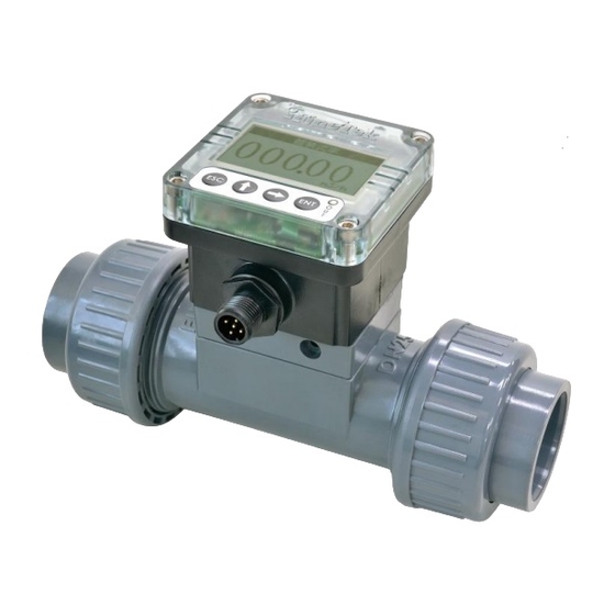
- Page 1 EPR1 Paddlewheel Flowmeter Operation Instruction FineTek Co.,Ltd. No.16, Tzuchiang St., Tucheng Industrial Park, New Taipei City 23678 Tel:886-2-22696789 Fax:886-2-22686682 Website:http://www.fine-tek.com E-mail:info@fine-tek.com 08-EPR1-B4-KM,10/09/2018...
-
Page 2: Table Of Contents
TABLE OF CONTENTS 1. Operation manual use ................1 2. Product warranty ..................2 2.1 New product warranty ................2 2.2 Repair warranty ................... 2 2.3 Service Network .................. 3 3. Product description ................... 4 3.1 Data label .................... 4 3.2 Contents of factory shipping carton ............. - Page 3 6.5.1 Switch Output Settings ................22 6.5.2 Current output settings ................23 6.5.3 Simulated Current Output ............... 23 6.5.4 Simulated Frequency Output..............23 6.5.5 Connection Settings ................. 24 6.6 System Settings ................24 6.6.1 System Language ..................24 6.6.2 Restore Default Settings ................. 25 6.6.3 Backlighting Settings ................
-
Page 4: Operation Manual Use
Please read this operation manual completely and carefully before installing the product. Please contact FineTek if this operation manual does not answer your questions. The content of this operation manual may be updated from time to time. Updates are Maintained on the FineTek website www.fine-tek.com... -
Page 5: Product Warranty
2. Product warranty 2.1 New product warranty Each FineTek EPR1 series paddlewheel flowmeter is backed by 1-year limited warranty. Should you experience a problem with one of our products deemed by our factory to be a product failure covered by our warranty, for a period of 1-year from the delivery date we will repair the unit at our factory or provide you with a replacement unit or sub-assembly at our discretion. -
Page 6: Service Network
355 S. Lemon Ave, Suite D, 1 909 598 3188 1 909 598 2488 Sensor Inc. Walnut, CA 91789 No. 60 Kaki Bukit Place, FineTek Pte Ltd. +65 6452 6340 +65 6734 1878 #07-06 Eunos Techpark 2 (Singapore Branch) Lobby B, Singapore 415979 Bei den Kämpen 26... -
Page 7: Product Description
3. Product description 3.1 Data label The data label includes the following information: product model type, power supply voltage, output type, operation temperature/pressure and other specifications 3.2 Contents of factory shipping carton Verify and inspect the contents you have received to ensure it is what you ordered/requested. -
Page 8: Product Features
3.5 Product features a. Microprocessor controlled, easy to operate and full featured b. Local LCD display/keypad for convenient setup (option). c. Totalization (displayed if unit so equipped; manual reset). d. Multiple outputs; DC pulse, 4-20mA/20-4mA analog and RS485 MODBUS serial link are standard. -
Page 9: Types & Specifications
3.6 Types & specifications Model Type EPR12 EPR10 EPR13 SPEC Flow transmitter Pulse output Intelligent All-in-one model model mode Applicable pipe DN20、DN25、DN40、DN50 diameter PVC、SUS304、SUS316、SUS316L Body material Flow velocity 0.3~10m/s range Under standard K Factor ±3%(Flow velocity 6~10m/s Accuracy reach±0.5% ) Linearity 0.5% F.S.(10m/s) Repeatability... - Page 10 Display LCM,128*64 Back-lit Power supply 12~36Vdc,±10% voltage Power <1.5VA consumption Reverse protection of power supply Communication RS485,Modbus port Accumulated flow storage 16K,FRAM device...
-
Page 11: Product Dimensions
4. Product Dimensions INTELLIGENT ALL-IN-ONE MODEL 71.3 44.3 FLOW TRANSMITTER MODEL & PULSE OUTPUT MODEL 56.1 50.3... -
Page 12: Epr13 With Keypad/Display
4.1 EPR13 with keypad/display Diameter- DN Standard (mm) (mm) (mm) (mm) (mm) (mm) (mm) DIN/ISO ASTM 26.7 76.3 26.45 CNS.4053-1 DIN/ISO 32.00 ASTM 33.40 76.7 32.55 DIN/ISO 50.00 ASIM 48.30 83.00 83.3 48.70 DIN/ISO ASTM 60.3 60.8 CNS.4053-1 Diameter- DN (mm) (mm) (mm) -
Page 13: Low Transmitter Model & Pulse Output Model
4.2 Low transmitter model & pulse output model (Engineering plastics) Standard (mm) (mm) (mm) (mm) (mm) (mm) (mm) DIN/ISO ASTM 26.7 54.8 26.45 CNS.4053-1 DIN/ISO 32.00 ASTM 33.40 55.2 32.55 DIN/ISO 50.00 ASTM 48.30 48.70 DIN/ISO ASTM 60.3 68.5 60.8 CNS.4053-1 Flow transmitter model &... -
Page 14: T-Fitting(Engineering Plastics)
4.3 T-fitting(engineering plastics) Standard (mm) (mm) (mm) (mm) (mm) (mm) DIN/ISO ASTM 26.7 26.45 CNS.4053-1 DIN/ISO 32.00 ASTM 33.40 32.55 DIN/ISO 50.00 ASTM 48.30 48.70 DIN/ISO ASTM 60.3 60.8 CNS.4053-1 Diameter- DN (mm) (mm) (mm) (mm) (mm) PF 1” PT 1” 55.6 NPT 1”... -
Page 15: Assembly Instructions
4.4 Assembly instructions Selecting flow and pipe diameter Flow Range (m3/h) Pipe diameter (mm) Flow velocity 0.3m/s(min) Flow velocity 10m/s(max) 0.34 11.31 0.53 17.67 1.35 45.23 2.12 70.68 Relationship between k value and fitting diameter K Factor (Pulse/Liter) Connection &... -
Page 16: Assembly Instructions
4.5 Assembly instructions With Keypad/display 1. Install the paddlewheel blade sub-assembly onto the T-fitting, and fasten in the corners using the four screws provided. 2. Insert the keypad/display sub-assembly into the hole in the paddlewheel blade sub-assembly with the M12 electrical connector facing you,and rotate the keypad/display sub-assembly clockwise to the horizontal level. -
Page 17: Troubleshooting
4.6 Troubleshooting Error Inspection Solution The pipe has fluidic Please check if the Display Type: Please remove the while the display blade is stuck by two screws on the side of Fig. 6 value hasn’t debris above; then please changed counterclockwise remove the display of Fig. -
Page 18: Mounting Location
4.7 Mounting location When installing the EPR1 paddlewheel flowmeter be sureto provide minimum upstream and downstream straight pipe run lengths for optimal performance and accuracy. Refer to the below illustrations for minimum straight pipe run lengths, specified in terms of a multiple of the pipe diameter (DN25 / 1”... - Page 19 The paddlewheel flowmeter can be installed in either a vertical or horizontal orientation. The following requirements must be adhered to: 1. For horizontal installations the paddlewheel flowmeter must always be installed level and not on an incline. 2. For vertical orientations the paddlewheel flowmeter should always be installed “plumb”...
-
Page 20: Wiring Instructions
5. Wiring instructions 5.1 Safety 1. Ensure that power to the paddlewheel flowmeter is disconnected so wiring is performed only in power-off status. 2. Check to make sure that the power supply meets the power supply voltage requirement specifications of the paddlewheel flowmeter. 3. -
Page 21: Power Supply Description
5.3 Power supply description 12~36VDC blue 5.4 Wiring (4-20)mA wiring: RS485 wiring: (4~20)mA 12~36VDC purple blue NPN wiring: PNP wiring: 12~36VDC 12~36VDC blue blue brown brown pink yellow yellow... -
Page 22: Epr13 Settings
6. EPR13 Settings 6.1 Operation Flowchart L/min 1.1.1 Volume Flow Rate Main Measuring L/hr 1.1.2 Unit 1.1 Menu Display A Set 1 000.00 m3/min 1.1.3 m3/hr m3/hr 1.1.4 Flow Velocity gal/min 1.1.5 Display B 000.00 gal/hr 1.1.6 K Factor K Factor kg/min 1.1.7 050.93... -
Page 23: Button Operations
6.2 Button Operations Button Function Return to the previous menu Volume flow rate Move up the cursor/Set 000 . 00 parameter values Move up the cursor/Select m 3 / hr the numbers for the parameter value Enter the selected item/Confirm the operation Enter the Main Menu (Press the two buttons) -
Page 24: Measuring Set
6.4 Measuring Set Measuring Set: It is provided to set the measuring parameters, such as unit, K factor of flow, pipe diameter, and filter setting. To enter the Main Menu from the measuring screen, please press simultaneously 6.4.1 Unit The measuring setting value can be in the unit of L/minutes, L/hour, m3/minute, m3/hour, gal/minute, gal/hour, kg/minute, kg/hour, ton/minute, and ton/hour. -
Page 25: Filter Set
6.4.4 Filter Set buttons to adjust the parameter value, and press button to confirm it. 6.4.5 Reset Total Reset Total buttons to adjust the parameter value, and press button to confirm it. 6.5 Output Signal Settings Output Signal Settings: It allows you to set the switch output type, current output type, simulated current output parameters, connection address and speed, etc. -
Page 26: Current Output Settings
6.5.2 Current output settings Current Type Current Out Set 21.6~4mA Current Type 4~21.6mA High Limit Current 20~4mA Low Limit Current 4~20mA Press button in the Current Output Settings to enter Current Type Settings. A total of 4 current output types are available: 21.6mA~4mA, 4~21.6mA, 20~4mA and 4~20mA. Finally, press button to save. -
Page 27: Connection Settings
6.5.5 Connection Settings DEVICE ADDRESS Connection Set 2.5.1 DEVICE ADDRESS Out Signal Set Current Out Set 0 0 1 DEVICE ADDRESS Simulate Current Simulate Freq BAUDRATE Connection Set To connect with the computer successfully, it requires the same address of the device, which is 001 by default. -
Page 28: Restore Default Settings
6.6.2 Restore Default Settings Recovery Default Press button to confirm the selection. All will be reset to the factory settings. 6.6.3 Backlighting Settings Backlighting 3.3.3 Operation Open Select the backlighting status based on user’s habits, and press button to save. 6.6.4 LCD Contrast LCD Contrast buttons to increase/decrease the contrast, and press... -
Page 29: Settings
7. Settings Function Description Unit (Please refer to 6.4.1) Set the unit of volume flow rate. K Factor (Please refer to 6.4.2) Set K factor of flow (0~999.99). Pipe Diameter (Please refer to 6.4.3) Select pipe diameter. Filter Settings (Please refer to 6.4.4) Set filter parameters (1~40). -
Page 30: Digital Communication Protocol
8. Digital Communication Protocol 8.1 Communication Protocol Table Address Types Definition default Range Unit Name (Dec) 4128 FLOAT32 Read 0~11 Display flow speed 4130 FLOAT32 Read 0~19.44 Display flow rate 4132 FLOAT32 Read 0~275 Display frequency value 4134 FLOAT32 Read 4~21.6 Display output current 4136... -
Page 31: Flow Rate Unit Status Table
24 Current top bottom 4235 UINT16 Read/Write 25 Flow Total Value 4237 FLOAT64 Read/Write 26 Flow Total Value High Bytes 4241 UINT32 Read 27 Flow Total Value Low Bytes 4243 UINT32 Read 28 Reset Total 4245 UINT16 Read/Write ※Remarks:The cumulative quantity is [(Cumulative highs*10 。... -
Page 32: Current Filter And Output Delay Parameter Status Table
8.1.2 Current Filter and Output Delay Parameter Status Table Current filter number Current Filter Delay(s) 0.05 0.25 0.75 default 1.25 1.75 8.1.3 Internal EEPROM Saving Table Save system var to EEPROM Save system to EEPROM Save system to EEPROM Save setting 8.1.4 Internal Parameter Saving Status Table Save calibration setting Save calibration setting... -
Page 33: Backlighting Settings Status Table
8.1.7 Backlighting Settings Status Table Frequency flag Background mode Background mode 8.1.8 Output Switch Status Table Language Switch top bottom NO, Switch NO (inverse) Switch top bottom NC, Switch NC 8.1.9 Current Output Status Table Background mode Current top bottom 21.6~4mA Current top bottom 4~21.6mA...
Need help?
Do you have a question about the EPR1 Series and is the answer not in the manual?
Questions and answers