
Related Manuals for Kohler Mira Select B14C


Summary of Contents for Kohler Mira Select B14C
- Page 1 Mira Select Thermostatic Mixing Valve Installation and User Guide For SPARES, ADVICE or REPAIRS please call us free on 0800 001 4040 (UK only) 1553346-W2-A...
- Page 2 Products manufactured by Kohler Mira Ltd are designed to be safe, provided that they are installed, used, and maintained in good working order, in accordance with our instructions and recommendations.
-
Page 3: Pack Contents
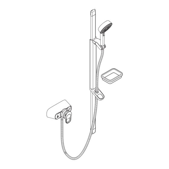
Pack Contents Mira Select Valve Box 1 x2 q x4 q x2 q x2 q x4 q x1 q Component Pack Documentation: Box 2 q Warnings and Cautions Guide q Quick Installation and User Guide q Installation Template x1 q Mira Single Outlet Shower Fittings x2 q x2 q... - Page 4 Pack Contents Mira Select Flex Shower Fittings Box 4 Box 3 x1 q x2 q x2 q x1 q x1 q x1 q x1 q x1 q 1553346-W2-A...
-
Page 5: Safety Information
Ensure that any pipework that could become frozen is properly insulated. DO NOT perform any unspecified modifications to the shower or its accessories. When servicing only use genuine Kohler Mira replacement parts. If the shower is dismantled during installation or servicing then, upon completion, an inspection must be made to ensure all connections are tight and that there are no leaks. - Page 6 Using the Shower The shower must be operated and maintained in accordance with the requirements of the installation and user guides. Make sure you read all this information fully and understand how to operate the shower before use. Retain all guides for future reference. 7.
- Page 7 18. DO NOT connect the outlet of the shower to any tap, control valve, trigger operated handset or showerhead other than those specified for use with this shower. Only Kohler Mira recommended accessories should be used. 19. For products with multiple shower outlets, the diverters or on/off controls must be regularly operated to ensure the correct operation of the outlet.
-
Page 8: Specifications
Specifications Pressures Maximum Static Pressure 1000 kPa (10 bar) Maximum Maintained Pressure 500 kPa (5 bar) Minimum Maintained Pressure 100 kPa (1 bar) (Gas Water Heater) (for optimum performance supplies should be nominally equal) Minimum Maintained Pressure 10 kPa (0.1 bar) (Gravity System) (0.1 bar = 1 Metre head from cold tank base to shower handset outlet) -
Page 9: Installation
Suitable Plumbing Installations The Thermostatic Mixer can be installed with all systems with balanced pressures. Mixed gravity and mains supplies are not recommended. Installation General Installation of the shower must be carried out in accordance with these instructions by qualified, competent personnel. The plumbing installation must comply with all national or local water regulations and all relevant building regulations, or any particular regulation or practice specified by the local water supply company. - Page 10 12. The position of the shower and shower fittings must provide a minimum air gap of 25 m m between the showerhead and the spill over level of any bath, shower tray or basin. There must be a minimum distance of 30 mm between the showerhead and the spill over lever of any toilet, bidet or other appliance with a Fluid Category 5 backflow risk.
- Page 11 Installation Scan this QR code to go to installation video. Note: If replacing the existing product with Mira Select, continue step (2) from page 13. New Installation Important! Isolate the water supplies before installing the shower. Note: Recommended installation height for the valve is 1050 mm, 720 mm for shower fittings and 1050 mm for soap dish from shower tray surface in new installations.
- Page 12 id e ll f r o v r e w I n l i n g in le la t a . ) F i x t h e li n f o r id e ll f p l a Ø...
- Page 13 Replacement Installation The adjustable elbows each have adjustment, allowing your thermostatic mixer to be connected to pipe centres ranging from 110 mm to 155 mm. Carefully remove the existing product and place on a flat surface. Refer to the installation guide supplied with the existing product for any help. 10-27 mm Retaining Clips Inlet pipes must extend 10-27 mm from the finished wall surface, and be square to...
- Page 14 For A = 135 mm - 155 mm and B < 10 mm Spirit Level Mixing Valve Note: Identification on the mixing valve shows the orientation that the valve must be fixed to the wall. Ensure the “TOP” marking faces to top of the product. Note: Slide the elbows to required pipe centers.
- Page 15 For A = 110 mm - 132 mm and B > 10 mm 1e 2e 1e 2e Inlet Port Inlet Cap Mixing Valve Inlet Port Remove the inlet caps from the optional Rotate the inlet ports towards the inlet inlet ports and retain for reinstallation. pipes.
- Page 16 For A = 135 mm - 155 mm and B > 10 mm Inlet Sleeves Mixing Valve Remove the inlet sleeves using 6 mm hex key. Note the "A" and "B" markings on the inlet sleeves. Swap the sleeves and fit onto the mixing valve oriented as shown. Inlet Port Inlet Port...
- Page 17 For A = 110 mm - 132 mm and B < 10 mm 1g 2g Inlet Sleeves Mixing Valve Remove the inlet sleeves using 6 mm hex key. Note the "A" and "B" markings on the inlet sleeves. Swap the sleeves and fit onto the mixing valve oriented as shown. 1g 2g Note: Slide the elbows to required pipe centers.
- Page 18 Compression Nuts Olive Mixing Valve Concealing Plate (New Product installation only) Note: Recycle if not required. 6 mm Hex Key Mixing Valve Flush the water supplies thoroughly before connecting the mixing valve. Note: Identification on the mixing valve shows the orientation that the valve must be fixed to the wall.
- Page 19 Reversed Inlet Supplies If the HOT water supply is on the RIGHT HAND side, the shower’s control cartridge must be reversed. The following steps show how to swap the hot and cold water inlet positions of the cartridge. Isolate the water supplies and turn the shower on / o ff to relieve the water pressure.
- Page 20 Note: Before fitting the shroud ensure inlet water supplies are isolated. Mixing Valve Handshower Outlet Shroud Rotate handle slightly to align. Align the splines in order to fit the shroud. Note: Ensure that the spline is oriented in line as shown. Mixing Valve Fits into Top Clip...
- Page 21 Single Outlet Shower Fitting Mounting Bracket (x2) Locking Peg 630 mm Wall Plugs (x2) 8 mm Wall Screws (x2) Locking peg on underside Mark the wall fixing positions and drill two holes to suit the wall fixings. Caution! Do not drill into cables or pipes in the wall. Note: Installation fixing centres are 630 mm for the 660 mm slidebar.
- Page 22 Locking Peg Hole Endcaps (x2) Slidebar Support (x2) Press the two buttons Clamp Bracket on the clamp bracket to adjust the position. Slidebar Retaining Ring Locking peg on underside Hole Install the clamp bracket, the hose retaining ring (smallest hole) and the slidebar supports to the slidebar.
- Page 23 Information for Flow Regulators: Handset Mira Select is pre-fitted with a 11 L/min flow regulator in the valve outlet to reduce water usage. For maintained pressures below 1 Bar, we recommend removing the flow regulator for improved performance. Shower Hose In high pressure installations, Shower Unit flow control may be limited, if...
- Page 24 Installation of Flex Shower Fitting Second Assembly Tool Ejects Clamp Bracket Assembly Tools (x2) Clamp Bracket Assembly First Assembly Tool Ejects Carefully remove paper wrap from the slide rail. Ensure both assembly tools are fully pushed down. Push the clamp bracket onto the slide rail until it reaches a stop. Place assembly upright in the vertical position (place a protective cover on the floor).
- Page 25 Push the end brackets into the both ends of the slide rail and make sure that end brackets are pushed firmly. Tighten the two screws to secure the end brackets onto the slide rail. 1553346-W2-A...
- Page 26 Hold the slide rail assembly against the Vertical Hole wall in the desired position. Mark the positions of the top and bottom fixing holes using the slide rail brackets as a template. Note: Use a spirit level to ensure the bar is vertical.
- Page 27 Fit the shower hose onto the bottom outlet of the mixing valve. The hose has a swivel end for easy handset alignment. Green end fits to the handset and red end fits to the valve. Information for Flow Regulators: • Mira Select pre-fitted with...
- Page 28 Ø 8 m m Decide on a suitable position for the Drill the two fixing holes for the soap soap dish avoiding any buried cables dish frame. and pipes. DO NOT drill through the soap dish frame into the wall. Place the soap dish frame on the wall DO NOT drill into buried cables or and mark the position of the fixing...
- Page 29 Operation of Flex Shower Fitting Clamp Bracket Slide Rail Handshower Clamp Bracket Assembly Slide the clamp bracket assembly up and down along with the slide rail until the handshower is positioned to your preference. Rotate the clamp bracket and handshower as shown to suit your preference. 1553346-W2-A...
- Page 30 Commissioning Maximum Temperature Setting Before using the shower, the maximum temperature must be checked to make sure that it is at a safe level. It has been preset to a safe showering temperature under ideal conditions at the factory, appropriate for most systems. However, site conditions and personal preference may make it necessary to reset this temperature.
- Page 31 Temperature Stop Ring Control Hub Default Position Clockwise = Warmer Anticlockwise = Cooler Temperature Stop Ring Splines 1 Spline = approx. 1°C 7. Remove the temperature stop ring and rotate by the required number of splines within the marked temperature range. 8.
-
Page 32: Operation
Operation Important! Read the 'Safety Information' before using your shower. Flow Control Handle Temperature Handle Decrease Temperature ON/OFF Button Increase Temperature On/Off and Temperature Control Press the ON/OFF button to turn the product ON or OFF. Adjusting the Temperature The temperature increases by rotating the temperature handle in anticlockwise direction. -
Page 33: User Maintenance
User Maintenance WARNING! PLEASE OBSERVE THE FOLLOWING TO REDUCE THE RISK OF INJURY OR PRODUCT DAMAGE: • DO NOT allow children to clean or perform any user maintenance to the shower unit without supervision. • If the shower is not to be used for a long period, the water supply to the shower unit should be isolated. - Page 34 Shroud Locate a large flat blade screwdriver behind the bottom-side edge of the shroud, gently twist the screwdriver to lever off the shroud while supporting the front. Pull off the shroud from valve assembly. Remove the inlet filters using 6 mm hex key. Rinse the filters in clean water, removing any dirt or debris.
- Page 35 Note: Before fitting the shroud ensure inlet water supplies are isolated. Mixing Valve Handshower Outlet Shroud Rotate handle slightly to align. Mixing Valve Align the splines in order to fit the shroud. Note: Ensure that the spline is oriented in line as shown above. Slide the shroud over the valve and push until clipped.
- Page 36 Cleaning Always read the IMPORTANT SAFETY INFORMATION for your shower. Cleaning the showerhead Many household and commercial cleaners, including hand and surface cleaning wipes contain abrasive and chemical substances that can damage plastics, plating and printing and should not be used. These finishes should be cleaned with a mild washing up detergent or soap solution, and then wiped dry using a soft cloth.
- Page 37 Spray Plate Removal 1. Insert the prongs (x2) of the spray plate removal tool supplied into the corresponding holes in the spray plate. 2. Turn the removal tool anticlockwise and unscrew the spray plate from the showerhead body. 3. Clean all the components with a stiff brush. If necessary use a plastic kettle descalent in accordance with the manufacturer's instructions.
-
Page 38: Fault Diagnosis
Fault Diagnosis If you require a Mira trained service engineer or agent, refer to ‘Customer Service’. Symptom Cause / R ectification Water too hot or too cold Inlets reversed (hot supply to cold supply). Refer to Reversed Inlet Supplies page 19 to reverse the Inlet supplies. Check filters for any blockage. - Page 39 We will use your information: (i) As necessary to fulfill our contract with you (including to recover We, along with other members of our Group and Kohler Mira any amounts owing); (ii) for our legitimate interests in: undertaking Limited may use your information to tell you about any offers, marketing (about our products and services and those of our products or services which may be of interest to you.
-
Page 40: Customer Service
Kohler Mira Limited. Cromwell Road, Kohler France S.A.S. Cheltenham, 30 Boulevard de la Bastille, The company reserves the right Gloucestershire 75012 Paris, to alter product specifications GL52 5EP France without notice. 14648 1553346-W2-A © Kohler Mira Limited, November 2023...
Need help?
Do you have a question about the Mira Select B14C and is the answer not in the manual?
Questions and answers