Komatsu GALEO D155AX-5 Operation & Maintenance Manual
Bulldozer
Hide thumbs
Also See for GALEO D155AX-5:
- Operation & maintenance manual (279 pages) ,
- Shop manual (296 pages)
Table of Contents
Advertisement
Quick Links
Advertisement
Chapters
Table of Contents

Related Manuals for Komatsu GALEO D155AX-5


Summary of Contents for Komatsu GALEO D155AX-5
- Page 2 1 - 1...
-
Page 3: Foreword
Keep this manual at the storage location for the Operation and Maintenance Manual given below, and have all personnel read it periodically. If this manual has been lost or has become dirty and cannot be read, request a replacement manual immediately from Komatsu or your Komatsu distributor. - Page 4 FOREWORD FOREWORD FOREWORD FOREWORD Machine equipped without cab Back pocket of operator's seat 1 - 3...
- Page 5 FOREWORD FOREWORD 1 - 4...
- Page 6 FOREWORD FOREWORD 1 - 5...
-
Page 7: Safety Information
FOREWORD SAFETY INFORMATION SAFETY INFORMATION To enable you to use this machine safely, safety precautions and labels are given in this manual and affixed to the machine to give explanations of situations involving potential hazards and of the methods of avoiding such situations. - Page 8 Continuing improvements in the design of this machine can lead to changes in detail which may not be reflected in this manual. Consult Komatsu or your Komatsu distributor for the latest available information of your machine or for questions regarding information in this manual.
-
Page 9: Introduction
BREAKING IN THE MACHINE NOTICE Your Komatsu machine has been thoroughly adjusted and tested before shipment from the factory. However, operating the machine under full load before breaking the machine in can adversely affect the performance and shorten the machine life. -
Page 10: Necessary Information
FOREWORD NECESSARY INFORMATION NECESSARY INFORMATION When requesting service or ordering replacement parts, please inform your Komatsu distributor of the following items. PRODUCT IDENTIFICATION NUMBER (PIN), MACHINE SERIAL NO. PLATE Under the front of the console box on the right side of the operator's seat. -
Page 11: Engine Serial No. Plate And Position
FOREWORD NECESSARY INFORMATION ENGINE SERIAL NO. PLATE AND POSITION (2) This is the same content as engine serial No. plate (1). Located on the top of the air cleaner mounting bracket on the left of the machine. This also acts as the EPA plate. EPA: Environmental Protection Agency, U.S.A. -
Page 12: Rops, Fops No. Plate Position
FOREWORD NECESSARY INFORMATION ROPS, FOPS NO. PLATE POSITION This is located at the top left. POSITION OF SERVICE METER On top of the machine monitor TABLE TO ENTER SERIAL NO. AND DISTRIBUTORN Machine serial No. Engine serial No. Product identification number (PIN) Distributor name Address Service Personnel... -
Page 13: Table Of Contents
FOREWORD CONTENTS CONTENTS FOREWORD FOREWORD SAFETY INFORMATION INTRODUCTION FRONT/REAR, LEFT/RIGHT DIRECTIONS OF MACHINE BREAKING IN THE MACHINE NECESSARY INFORMATION PRODUCT IDENTIFICATION NUMBER (PIN), MACHINE SERIAL NO. PLATE ENGINE SERIAL NO. PLATE AND POSITION (1) ENGINE SERIAL NO. PLATE AND POSITION (2) 1- 10 BLADE SERIAL NO. - Page 14 FOREWORD CONTENTS OPERATIONS AND CHECKS AFTER STARTING ENGINE 3- 91 STOPPING ENGINE 3- 94 MOVING MACHINE OFF 3- 95 STOPPING MACHINE 3- 97 SHIFTING GEAR 3- 98 SHIFTING BETWEEN FOEWARD AND REVERSE 3-102 STEERING MACHINE 3-104 PRECAUTIONS FOR OPERATION 3-106 PARKING MACHINE 3-108 CHECK AFTER STOPPING ENGINE...
- Page 15 FOREWORD CONTENTS MAINTENANCE SCHEDULE CHART 4- 17 MAINTENANCE SCHEDULE CHART 4- 17 SERVICE PROCEDURE 4- 19 INITIAL 250 HOURS SERVICE(ONLY AFTER THE FIRST 250 HOURS) 4- 19 WHEN REQUIRED 4- 20 CHECK BEFORE STARTING 4- 42 EVERY 250 HOURS SERVICE 4- 43 EVERY 500 HOURS SERVICE 4- 52...
- Page 16 2 - 1...
-
Page 17: Safety
SAFETY SAFETY SAFETY Safety Labels Positions of Safety Pictograms Safety Labels General Precautions Safety Rules 2- 11 If Abnormalities Are Found 2- 11 Clothing and Personal Protective Items 2- 11 Fire Extinguisher and First Aid Kit 2- 11 Safety Features 2- 11 Keep Machine Clean 2- 12... - Page 18 SAFETY SAFETY Precautions for Operation 2- 19 Before Starting Engine 2- 19 Checks Before Starting Engine 2- 19 Precautions When Starting 2- 19 Precautions in Cold Areas 2- 20 Operation 2- 21 Checks Before Operation 2- 21 Precautions When Moving Machine Forward or in Reverse 2- 21 Precautions When Traveling 2- 22...
-
Page 19: Safety Labels
SAFETY SAFETY LABELS SAFETY LABELS POSITIONS OF SAFETY PICTOGRAMS 2 - 4... -
Page 20: Safety Labels
SAFETY SAFETY LABELS SAFETY LABELS (1) Precautions for operation, inspection and maintenance (09651-03001) (2) Precautions when traveling in reverse (09802-13000) (3) Precautions for leaving the operator's seat (09654-33001) 2 - 5... - Page 21 SAFETY SAFETY SAFETY LABELS SAFETY LABELS (4) Precautions for high-temperature hydraulic oil (09653-03001) (5) Precautions for high-temperature cooling water (09668-03001) (6) Precautions when adjusting track tension (09657-03003) Safety label is attached to the back side of the inspection cover of the track frame. (7) Precautions for handling accumulator (09659-53000) 2 - 6...
- Page 22 SAFETY SAFETY SAFETY LABELS SAFETY LABELS (8) Precautions for use of seat belt (195-98-12940) (9) Precautions when handling cable (09808-03000) (10) Caution about going on top of fuel tank (17A-98-23920) 2 - 7...
- Page 23 SAFETY SAFETY SAFETY LABELS SAFETY LABELS (11) Prohibition of running engine during inspection and maintenance (09667-03001) (12) Caution about going close when machine is moving (09812-03000) (13) Caution for high voltage (7872-10-1600) 2 - 8...
- Page 24 SAFETY SAFETY SAFETY LABELS SAFETY LABELS (14) Jump start prohibited (09842-A0481) (15) ROPS (09620-B2000) (16) FOPS (09620-C2000) 2 - 9...
- Page 25 SAFETY SAFETY SAFETY LABELS SAFETY LABELS (17) Precautions when handling battery 2 - 10...
-
Page 26: General Precautions
SAFETY GENERAL PRECAUTIONS GENERAL PRECAUTIONS SAFETY RULES Only trained and authorized personnel can operate and maintain the machine. Follow all safety rules, precautions and instructions when operating or performing maintenance on the machine. If you are under the influence of alcohol or medication, your ability to safely operate or repair your machine may be severly impaired putting yourself and everyone else on your jobsite in danger. -
Page 27: Keep Machine Clean
SAFETY GENERAL PRECAUTIONS KEEP MACHINE CLEAN If water gets into the electrical system, there is a hazard that it will cause malfunctions or misoperation. Do not use water or steam to wash the electrical system (sensors, connectors). If inspection and maintenance is carried out when the machine is still dirty with mud or oil, there is a hazard that you will slip and fall, or that dirt or mud will get into your eyes. -
Page 28: Handrails And Steps
SAFETY GENERAL PRECAUTIONS HANDRAILS AND STEPS To prevent personal injury caused by slipping or falling off the machine, always do as follows. Use the parts marked by arrow A in the diagrams when getting on or off the machine. Never use the parts marked by arrow B when getting on or off the machine. -
Page 29: Prevention Of Burns
SAFETY GENERAL PRECAUTIONS PREVENTION OF BURNS Hot coolant To prevent burns from hot water or steam spurting out when checking or draining the coolant, wait for the water to cool to a temperature where it is possible to touch the radiator cap by hand before starting the operation. -
Page 30: Action If Fire Occurs
SAFETY GENERAL PRECAUTIONS Fire coming from accumulated flammable materials Remove any flammable materials such as dry leaves, chips, pieces of paper, or coal dust accumulated near the engine exhaust manifold, muffler, or battery. Prevention of fire spreading To prevent fires spreading from sparks or burning particles from other fires, remove any flammable materials such as dry leaves, chips, or coal dust accumulated around the cooling system (radiator, oil cooler) or inside the undercover. -
Page 31: Precautions When Using Rops
Any modification made without authorization from Komatsu can create hazards. Before making a modification, consult your Komatsu distributor. Komatsu will not be responsible for any injuries, accidents, product failures or other property damages resulting from modifications made without authorization from Komatsu. -
Page 32: Working On Loose Ground
SAFETY GENERAL PRECAUTIONS WORKING ON LOOSE GROUND Avoid traveling or operating your machine too close to the edge of cliffs, overhangs, and deep ditches. The ground may be weak in such areas. If the ground should collapse under the weight or vibration of the machine, there is a hazard that the machine may fall or tip over. -
Page 33: Ventilation For Enclosed Areas
Do not allow other persons to approach during the operation. Always observe the rules and regulations for the work site and environmental standards. This machine does not use asbestos, but there is a danger that imitation parts may contain asbestos, so always use genuine Komatsu parts. 2 - 18... -
Page 34: Precautions For Operation
SAFETY PRECAUTIONS FOR OPERATION PRECAUTIONS FOR OPERATION BEFORE STARTING ENGINE If there is a warning tag hanging from the work equipment control lever, do not start the engine or touch the levers . CHECKS BEFORE STARTING ENGINE Carry out the following checks before starting the engine at the beginning of the day's work. Completely remove all flammable materials accumulated around the engine and battery, and remove any dirt from the windows, mirrors, handrails and steps. -
Page 35: Precautions In Cold Areas
SAFETY PRECAUTIONS FOR OPERATION PRECAUTIONS IN COLD AREAS Carry out the warming-up operation thoroughly. If the machine is not thoroughly warmed up before the control levers are operated, the reaction of the machine will be slow, and this may lead to unexpected accidents. If the battery electrolyte is frozen, do not charge the battery or start the engine with a different power source. -
Page 36: Operation
SAFETY PRECAUTIONS FOR OPERATION OPERATION CHECKS BEFORE OPERATION When carrying out the checks, move the machine to a wide area where there are no obstructions, and operate slowly. Do not allow anyone near the machine. Always fasten your seat belt. Check the operation of travel, steering and brake systems, and work equipment control system. -
Page 37: Precautions When Traveling
SAFETY PRECAUTIONS FOR OPERATION PRECAUTIONS WHEN TRAVELING Never turn the starting switch to the OFF position when traveling. It is dangerous if the engine stops when the machine is traveling. When the engine is off, it is impossible to operate the steering. Apply the brakes and stop the machine immediately, if the engine stops. -
Page 38: Traveling On Slopes
SAFETY PRECAUTIONS FOR OPERATION TRAVELING ON SLOPES To prevent the machine from tipping over or slipping to the side, always do as follows. When traveling on slops, keep the blade approxmately 20 to 30cm (8 to 12in) above the ground. In case of emergency, quickly lower the blade to the ground to help the machine to stop. -
Page 39: Parking Machine
SAFETY PRECAUTIONS FOR OPERATION PARKING MACHINE Park the machine on level ground where there is no danger of falling rocks or landslides, or of flooding if the land is low, and lower the work equipment to the ground. If it is necessary to park the machine on a slope, set the blocks under the tracks to prevent the machine from moving, then dig the work equipment into the ground. -
Page 40: Transportation
PRECAUTIONS FOR OPERATION TRANSPORTATION The machine can be divided into parts for transportation, so when transportating the machine, please contact your Komatsu distributor to have the work carried out. SHIPPING When shipping the machine on a trailer, do as follows. -
Page 41: Battery
SAFETY PRECAUTIONS FOR OPERATION BATTERY BATTERY HAZARD PREVENTION Battery electrolyte contains sulphuric acid, and batteries generate flammable hydrogen gas, which may explode. Mistaken handling can lead to serious injury or fire. For this reason, always observe the following precautions. When working with batteries, always wear safety glasses and rubber gloves. Never smoke or use any flame near the battery. -
Page 42: Starting With Booster Cable
SAFETY PRECAUTIONS FOR OPERATION STARTING WITH BOOSTER CABLE If any mistake is made in the method of connecting the booster cables, it may cause the battery to explode, so always do as follows. When starting with a booster cable, carry out the starting operation with two workers (one worker sitting in the operator's seat and the other working with the battery). -
Page 43: Towing
When working with others to prepare for towing, signals should be agreed upon beforehand. If your machine is towed by another machine, stop the engine and release the brake. Please contact your Komatsu distributor to have the brake released. Towing on slopes is dangerous. When doing so, choose a gentle slope. -
Page 44: Precautions For Maintenance
SAFETY PRECAUTIONS FOR MAINTENANCE PRECAUTIONS FOR MAINTENANCE WARNING TAG Always attach the "DO NOT OPERATE" warning tag to the work equipment control lever in the operator's cab to alert others that you are performing service or maintenance on the machine. Attach additional warning tags around the machine if necessary. -
Page 45: Stop Engine Before Carrying Out Inspection And Maintenance
SAFETY PRECAUTIONS FOR MAINTENANCE STOP ENGINE BEFORE CARRYING OUT INSPENTION AND MAINTENANCE Stop the machine on firm, level ground. Select a place where there is no hazard of falling rocks or landslides, or of flooding if the land is low. Lower the work equipment completely to the ground and stop the engine. -
Page 46: Two Workers For Maintenance When Engine Is Running
SAFETY PRECAUTIONS FOR MAINTENANCE TWO WORKERS FOR MAINTENANCE WHEN ENGINE IS RUNNING To prevent injury, do not carry out maintenance with the engine running. If maintenance must be carried out with the engine running, carry out the operation with at least two workers and do as follows. -
Page 47: Handling Accumulator
Do not weld any boss to the accumulator. When disposing of the accumulator, it is necessary to release the gas from the accumulator. A special air bleed valve is necessary for this operation, please contact your Komatsu distributor. PERSONNAL Only authorized personnel can service and repair the machine. Do not allow unauthorized personnel into the area. -
Page 48: Noise
SAFETY PRECAUTIONS FOR MAINTENANCE NOISE When carrying out maintenance of the engine and you are exposed to noise for long periods of time, wear ear covers or ear plugs while working. If the noise from the machine is too loud, it may cause temporary or permanent hearing problems. PRECAUTIONS WHEN USING HAMMER When using a hammer, pins may fly out or metal particles may be scattered. -
Page 49: Do Not Disassemble Recoil Spring
If it is disassembled by mistake, the spring will fly out and cause serious injury. When it becomes necessary to disassemble it, ask your Komatsu distributor to do the work. PRECAUTION WITH HIGH-PRESSURE OIL The hydraulic system is always under internal pressure. -
Page 50: Precaution For High Voltage
If it is necessary to touch the inside of the controller or the engine injector portion, please contact your Komatsu distributor. WASTE MATERIAL To prevent pollution, pay careful attention to the method of disposing of waste materials. - Page 51 3 - 1...
-
Page 52: General View
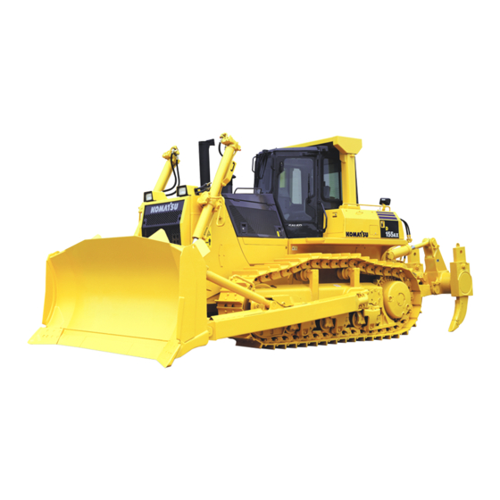
OPERATION GENERAL VIEW GENERAL VIEW GENERAL VIEW OF MACHINE Blade Multi ripper Blade tilt cylinder Ripper lift cylinder Blade lift cylinder Sprocket (10) Track frame Track shoe (11) Frame Ripper tilt cylinder (12) Idler 3 - 2... -
Page 53: General View Of Controls And Gauges
OPERATION GENERAL VIEW GENERAL VIEW OF CONTROLS AND GAUGES Parking lever (12) Starting switch Safety lock lever (13) Information switch Cigarette lighter (14) Buzzer cancel switch Fuel control dial (15) Brake pedal Joystick (16) Deceleration pedal (Steering, directional and gear shift lever) (17) Blade control lever Auto shift down switch... - Page 54 OPERATION GENERAL VIEW FRONT PANEL Engine cooling water temperature gauge (10) Engine preheating pilot lamp Power train oil temperature gauge (11) Maintenance caution lamp Hydraulic oil temperature gauge (12) Warning lamp Fuel level gauge (13) Filter, oil change interval lamp Charge monitor (14) Display panel A (Speed range, Engine speed)
-
Page 55: Explanation Of Components
OPERATION EXPLANATION OF COMPONENTS EXPLANATION OF COMPONENTS The following is an explanation of the devices needed for operating the machine. To perform suitable operations correctly and safely, it is important to completely understand the methods of operating equipment and meanings of the displays. FRONT PANEL Basic check items Meter group... - Page 56 OPERATION EXPLANATION OF COMPONENTS B: Caution monitor group (see "CAUTION MONITOR GROUP (PAGE 3-9)") CAUTION If the caution lamp for any of these items flashes, check and repair the appropriate item as soon as possible. These are items, which need to be observed while the engine is running. If any abnormality occurs, items, which need to be repaired as soon as possible, are displayed.
- Page 57 Park the machine on level ground and then check the monitor lamps. Confirm that monitor lamps light up about 2 seconds after the ignition switch is turned to the ON position. If any monitor lamp does not light, contact your Komatsu distributor to inspect and repair. REMARK When the ignition switch is turned to the ON position, before starting the engine, the caution lamps flashes for 2 seconds, the warning lamps light up for 2 seconds, and the alarm buzzer sounds for 2 seconds.
- Page 58 OPERATION EXPLANATION OF COMPONENTS MAINTENANCE CAUTION LAMP This lamp (1) flashes when the time for changing the filter or oil has been exceeded. "SWITCH DISPLAY PANEL B (Multi-information) (PAGE 3-15)" to the maintenance mode, and check or replace the appropriate filter or oil. 3 - 8...
- Page 59 Confirm that monitor lamps light up about 2 seconds after the ignition switch is turned to the ON position. If any monitor lamp does not light, contact your Komatsu distributor to inspect and repair. These are items which need to be observed when the engine is running. If any abnormality occurs, the item needing immediate repair is displayed.
- Page 60 Confirm that these caution lamps light for about 2 seconds after the ignition switch is turned to ON. If any monitor lamp does not light, have your Komatsu distributor inspect and repair it. These items need to be observed while the engine is running. If any abnormality occurs, items that need to be repaired immediately are displayed.
- Page 61 OPERATION EXPLANATION OF COMPONENTS ENGINE OIL PRESSURE CAUTION LAMP This lamp (1) indicates a low engine oil pressure. If the monitor lamp flashes, stop the engine and check it immediately. REMARK The alarm buzzer sounds, when the starting switch is turned to ON immediately after the engine oil has been changed.
- Page 62 OPERATION EXPLANATION OF COMPONENTS HSS CHARGE PRESSURE CAUTION LAMP This monitor (5) warns the operator that the HSS charge pressure has dropped. If it flashes, stop the engine and carry out inspection. REMARK The buzzer may sound when the starting switch is turned ON or immediately after the engine is started, but this does not indicate any abnormality.
- Page 63 When the engine is stopped, turn that the starting switch to the ON position and check that the gauge or monitor for the engine water temperature gauge, power train oil temperature gauge, and fuel gauge light up. If they do not light up, please contact your Komatsu distributor for repairs. D(1)
- Page 64 OPERATION EXPLANATION OF COMPONENTS POWER TRAIN OIL TEMPERATURE GAUGE Gauge (2) indicates the torque converter outlet oil temperature. If the temperature is normal during operation, green range (B) will light. If red range (C) lights up during operation, move the fuel control dial to lower engine speed to approx.
- Page 65 OPERATION EXPLANATION OF COMPONENTS ENGINE PREHEATING PILOT LAMP Lamp (5) indicates that engine is being preheated bu the electrical heater during cold weather. The engine controller detects the coolant temperature and automatically actuates preheating in low temperatures when starting the engine. DISPLAY PANEL A (speed range display, engine speed) Meter (6) displays the transmission speed range being used on the machine and engine speed.
- Page 66 OPERATION OPERATION EXPLANATION OF COMPONENTS EXPLANATION OF COMPONENTS (2) Maintenance mode The maintenance mode is displayed by continuing to turn the information switch in the direction for 2.5 seconds. For details, see "METHOD OF USING DISPLAY PANEL B (Multi-information) (PAGE 3-22)". 3 - 16...
- Page 67 OPERATION EXPLANATION OF COMPONENTS SWITCH E(1) Starting switch E(5) Rear lamp switch E(2) Buzzer cancel switch E(6) Fan rotation selector switch E(3) Information switch E(7) Auto shift down switch E(4) Front lamp switch STARTING SWITCH Switch (1) is used to start the engine. Key insertion-withdrawal position.
- Page 68 OPERATION EXPLANATION OF COMPONENTS BUZZER CANCEL SWITCH When this switch (2) is turned to the right, the alarm buzzer stops. When the information monitor is in the maintenance mode, this switch is used to select the mode item. Position (a): Cancel Position (b): Select INFORMATION SWITCH This switch (3) is used to switch the display mode item on the...
- Page 69 OPERATION EXPLANATION OF COMPONENTS FAN ROTATION SELECTOR SWITCH This switch (6) is used to switch the fan to the reverse mode and clean mode. Position (a): Normal mode Position (b): Reverse mode Position (c): Clean mode Use the reverse mode in cold weather to maintain the temperature and use the clean mould when removing dirt and foreign material clogging the radiator.
- Page 70 OPERATION EXPLANATION OF COMPONENTS LAMPS F(1) Warning lamp F(3) Fan operation confirmation lamp F(2) Filter, oil change interval lamp WARNING LAMP NOTICE If alarm buzzer sounds, stop work immediatey and perform inspection and maintenance of the appropriate point. When the caution lamp for the B CAUTION or C CAUTION groups flashes and an abnormality is detected by the electronic control system, the alarm buzzer sounds and this lamp (1) flashes at the same time.
- Page 71 OPERATION EXPLANATION OF COMPONENTS FILTER, OIL CHANGE INTERVAL LAMP This lamp (2) lights up when the time for replacing the filter or oil is near. FAN OPERATION CONFIRMATION LAMP After the engine is started, even if the fan rotation selector switch is operated, this lamp will flash to inform the operator that the switching operation cannot be carried out.
- Page 72 OPERATION EXPLANATION OF COMPONENTS METHOD OF USING DISPLAY PANEL B (Multi-information) EXPLANATION OF MODES AND CONTROLS Display panel B (1) has the function of displaying the following four types of mode. (The diagram on the right shows the normal screen before the mode display.) Maintenance mode This displays the time for replacing the filters or oil.
- Page 73 OPERATION EXPLANATION OF COMPONENTS METHOD OF SELECTING MODES 1. When moving from the normal operation display to a user mode, the maintenance mode is displayed. Use the controls to change the mode as follows. > position: Go to PM clinic auxiliary mode <...
- Page 74 This function is only a guideline. If dirty oil or filters are found during daily maintenance, replace them immediately. If the controllers or monitor panel are replaced, the timer for this function will not worl properly. Contact your Komatsu distributor for replacement.
- Page 75 OPERATION OPERATION EXPLANATION OF COMPONENTS EXPLANATION OF COMPONENTS REMARK To return to the function selection mode, operate the buzzer cancel switch to 3 - 25...
- Page 76 OPERATION EXPLANATION OF COMPONENTS METHOD OF USING PM CLINIC AUXILIARY MODE CAUTION When moving the work equipment or setting the transmission to the travel position for carrying out measurements, check carefully that the situation is safe. The PM clinic auxiliary mode displays the engine speed, hydraulic oil pressure, and other items on display panel B. Display panel B displays the item on the top line (1), and the measured value on the bottom line (2).
- Page 77 When any disconnection or short circuit in any sensor is detected, the location and fault code are displayed by a 6-digit code on display panel B. When contacting your Komatsu distributor, inform your distributor of the code at the same time.
- Page 78 OPERATION EXPLANATION OF COMPONENTS METHOD OF USING USER ADJUST MODE With the user adjust mode, the brightness of the panel screen backlighting and the contrast of the liquid crystal panel can be changed, or the cooling fan can be set to maximum speed to clean the radiator when it is clogged. These are displayed on display panel B.
- Page 79 OPERATION OPERATION EXPLANATION OF COMPONENTS EXPLANATION OF COMPONENTS The brightness can be adjusted by operating the information switch. The higher the number, the brighter the screen becomes; the lower the number, the darker the screen becomes. > position: Number increases <...
- Page 80 OPERATION EXPLANATION OF COMPONENTS REMARK To return to the function selection mode, operate the buzzer cancel switch to The brightness of the backlighting of the monitor panel differs according to whether the front lamp is lighted up or not. Entering this mode when the front lamps are lighted up makes it possible to adjust the brightness when the front lamps are lighted up.
-
Page 81: Switches
OPERATION EXPLANATION OF COMPONENTS SWITCHES Horn switch Cigarette lighter (24V) Room lamp switch Accessory socket (12V) Wiper switch HORN SWITCH The horn sounds when button (1) at rear of the blade control lever at the right side of operator's seat is pressed. 3 - 31... - Page 82 OPERATION EXPLANATION OF COMPONENTS ROOM LAMP SWITCH This (2) lights up the room lamp. ON position: Lamp lights up OFF position: Lamp is out WIPER SWITCH Switch (3) activates the wipers. The wiper switches are as follows. (LH) Left door (FF) Front window (RH) Right door (RR) Rear window...
- Page 83 OPERATION OPERATION EXPLANATION OF COMPONENTS EXPLANATION OF COMPONENTS Wiper and window washer If this is kept pressed to the ON position while the wiper is working, water will be sprayed out. If the intermittent switch is turned ON, all movement of the wipers will be intermittent.
- Page 84 When installing the cab, check the colors and install the washer tank and each window washer hose correctly according to the color. When installing the cab, carry out the operation in accordance with the cab installation procedure manual held by your Komatsu distributor. 3 - 34...
- Page 85 OPERATION EXPLANATION OF COMPONENTS CIGARETTE LIGHTER Lighter (4) is used to light cigarettes. When the cigarette lighter is pushed in, it will return to its original position after a few seconds, so take it out to light your cigarette. Cigarette lighter capacity: 120W NOTICE This cigarette lighter is 24V.
-
Page 86: Control Levers, Pedals
OPERATION EXPLANATION OF COMPONENTS CONTROL LEVERS, PEDALS Fuel control dial Safety lever Joystick Blade control lever (steering, directional and gear shift lever) Ripper control lever (Variable ripper) Brake pedal Pin puller control switch (giant ripper) Deceleration pedal (if equipped) Parking lever FUEL CONTROL DIAL Dial (1) is used to control the engine speed and output. - Page 87 OPERATION EXPLANATION OF COMPONENTS JOYSTICK (STEERING, DIRECTIONAL AND GEAR SHIFT LEVER) (PCCS lever) This lever (2) is used to switch between forward and reverse, to steer the machine, or carry out counterrotation turns. REMARK PCCS: Palm command control system Forward-reverse shifting Position (a): FORWARD Position (b): REVERSE Position N: Neutral...
- Page 88 OPERATION OPERATION EXPLANATION OF COMPONENTS EXPLANATION OF COMPONENTS Operating counterrotation turn WARNING When operating the counterrotation turn, if the load on the left and right is not balanced, the machine may make a pivot turn, so check the ground conditions and be careful not to hit any obstacles when carrying out the operation.
- Page 89 OPERATION EXPLANATION OF COMPONENTS PARKING LEVER WARNING When the machine is parked, always set the parking lever to the LOCK position. Lever (5) is used to apply the parking brake. REMARK Before moving the parking lever to the LOCK position, return the steering, directional, and gearshift lever to the N position.
- Page 90 OPERATION EXPLANATION OF COMPONENTS BLADE CONTROL LEVER Single tiltdozer Lever (7) is used to raise or tilt the blade. Lifting control (a) RAISE: (b) HOLD: Blade is stopped and held in this position. (c) LOWER: (d) FLOAT: Blade will move freely according to external force. REMARK When the lever is at the FLOAT position and it is released, it will not return automatically to the HOLD position, so return it by...
- Page 91 OPERATION EXPLANATION OF COMPONENTS RIPPER CONTROL LEVER This lever (8) is used to operate the ripper. (a) RAISE (b) HOLD: Ripper stops and stays in same position (c) LOWER (A) Digging angle reduced: Cutting angle (α) becomes smaller. (B) Digging angle increased: Cutting angle (α) becomes larger. PIN PULLER CONTROL SWITCH Switch (9) is used to operate the pin puller.
-
Page 92: Dust Indicator
OPERATION EXPLANATION OF COMPONENTS DUST INDICATOR This informs the operator if the air cleaner element becomes clogged. For details of the method for cleaning the element, see "WHEN REQUIRED (PAGE 4-20). POWER SOURSE It is possible to remove the cigarette lighter and use the socket as a power supply. Capacity of cigarette lighter: 120W (24V x 5A) NOTICE Do not use this as the power supply for 12V equipment. -
Page 93: Fuse Box
OPERATION EXPLANATION OF COMPONENTS FUSE BOX NOTICE Before replacing a fuse, be sure to turn ignition switch to the OFF position. Fuses protect the electrical equipment and wiring from burning out. If a fuse becomes corroded, or white powder can be seen, or a fuse is loose in the holder, replace the fuse. Replace a fuse with another of the same capacity. - Page 94 OPERATION OPERATION EXPLANATION OF COMPONENTS EXPLANATION OF COMPONENTS Cab (machines equipped with cab) Fuse box is installed at the bottom of the overhead panel. 3 - 44...
- Page 95 Do not keep the circuit breaker reset button pressed. If the starting motor does not work even when the circuit breaker has been reset, contact your Komatsu distributor.
- Page 96 OPERATION EXPLANATION OF COMPONENTS FUSE CAPACITY AND NAME OF CIRCUIT FUSE BOX I (1) Fuse box fs1 Fuse Circuit capacity Additional heater, Spare power source Horn, Ribbon heater Head lamp Rear lamp Transmission Steering controller (2) Fuse box fs2 Fuse Circuit capacity Monitor panel...
-
Page 97: Door Pocket
OPERATION EXPLANATION OF COMPONENTS DOOR POCKET This is inside the left and right doors. Use it for keeping things. Do not put the heavy tools or other heavy objects in it. If the pocket is dirty, loosen four bolts (1), then remove the pocket and rinse it. -
Page 98: Car Radio, Handling
OPERATION EXPLANATION OF COMPONENTS CAR RADIO, HANDLING EXPLANATION OF COMPONENTS Power switch, volume knob Seek button (SEEK) Tone Control Knob Tuning Button Display Preset Station Buttons Display selector button (CLOCK) FM/AM selector button (BAND) Station selection button (AST) POWER SWITCH, VOLUME KNOB When this knob (1) is turned clockwise from the OFF position, a click is heard and the power is turned on. - Page 99 OPERATION EXPLANATION OF COMPONENTS STATION SELECTOR BUTTON (AST) When this button (5) is pressed, the preset stations are called up in turn. When the desired broadcasting station is reached, press the button again to stop it. If this button is kept pressed for 2 seconds, it switches to auto memory. SEEK BUTTON (SEEK) When this button (6) is pressed, it automatically searches for stations that can be received.
- Page 100 OPERATION EXPLANATION OF COMPONENTS METHOD OF USE METHOD OF LISTENING TO RADIO 1. Turn the starting switch ON, then turn radio power switch (1) 2. Use BAND button (9) to select AM or FM. 3. Select the channel with PRESET STATION button (8) or TUNE button (7).
- Page 101 OPERATION EXPLANATION OF COMPONENTS METHOD OF PRESETTING 1. Select the desired preset station. Use BAND button (9) to select FM or AM, then use TUNE button (7) to select the frequency of the broadcasting station. 2. Decide one of preset buttons (8) to be used for the preset station, and keep it pressed for 2 seconds.
- Page 102 OPERATION EXPLANATION OF COMPONENTS MONAURAL/STEREO AUTOMATIC SELECTION RECEPTION If the reception of the FM stereo broadcast is weak (when you are far from the broadcasting station or are surrounded by hills), the radio is automatically switched from stereo to monaural to reduce the interference. When the stereo broadcast becomes stronger, it automatically switches back to stereo broadcasting.
-
Page 103: Car Stereo, Handling
OPERATION EXPLANATION OF COMPONENTS CAR STEREO, HANDLING EXPLANATION OF COMPONENTS Power switch/volume Cassette door Auto-store/preset scan button Fast forward, rewind buttons Bass control knob (10) Preset buttons Treble control knob (11) Metal tape button Loudness button (12) Manual tuning buttons Time/radio display selector button (13) Seek tuning buttons... - Page 104 OPERATION EXPLANATION OF COMPONENTS POWER SWITCH/VOLUME Turn this knob (1) to the right until it clicks to turn the power on. Turn it further to increase the volume. AUTO-STORE/PRESET SCAN BUTTON Use this button (2) to actuate the preset scan and auto-store functions. Auto-store Each time this button is pressed for more than 2 seconds while in radio reception, this auto-store function automatically starts to search for the desired station within a receivable band, and memorize the frequency in the...
- Page 105 OPERATION EXPLANATION OF COMPONENTS TAPE EJECT BUTTON This button (7) is used to stop the tape and to eject the cassette. When this button is pressed, the tape is ejected and the radio plays. CASSETTE DOOR Set the cassette with the exposed portion of the tape on the right side and insert it through the cassette door (8). FAST FORWARD, REWIND BUTTONS These buttons (9) are used to fast forward or rewind the tape.
- Page 106 OPERATION EXPLANATION OF COMPONENTS METOD OF OPERATION METHOD OF SETTING PRESET BUTTONS To listen to a preset station, use band selector button (1) to select AM, FM1, or FM2, then press the preset switch number to listen to the desired station. It is possible to preset six AM stations and 12 FM stations (FM1: 6, FM2: 6).
- Page 107 OPERATION EXPLANATION OF COMPONENTS LISTENING TO RADIO 1. Turn the starting switch ON, then turn power switch (1) ON. 2. Set band selector button (2) to AM or FM. 3. Select the station with the preset buttons or manual tuning button (3).
- Page 108 If the sound cannot be heard, nothing is displayed, or any other abnormality occurs, turn off the power switch and ask your Komatsu distributor, as soon as possible, to carry repairs. Stow the antenna when traveling in places with low overhead clearance.
-
Page 109: Air Conditioner
OPERATION EXPLANATION OF COMPONENTS AIR CONDITIONER GENERAL LOCATIONS AND FUNCTION OF CONTROL PANEL Fan switch Fresh/recirc selector switch Air conditioner switch Temperature control switch FAN SWITCH This switch (1) can be used to adjust the air flow in four stages. It also acts as the main switch for the air conditioner. - Page 110 OPERATION EXPLANATION OF COMPONENTS AIR CONDITIONER SWITCH This switch (2) is used to start or stop the cooling or dehumidifying function. When the fan switch is turned ON and the air conditioner switch is pressed, the indicator lamp above the switch lights up. When the switch is pressed again, the switch is turned OFF and the indicator lamp goes out.
- Page 111 OPERATION EXPLANATION OF COMPONENTS TEMPERATURE CONTROL SWITCH This switch (4) can be used to adjust the temperature steplessly between low temperature and high temperature. The temperature level indicator lamps light up to display the temperature of the air coming from the vents. The more the blue lamps light up, the lower the temperature is.
- Page 112 OPERATION EXPLANATION OF COMPONENTS WHEN NOT USING THE AIR CONDITIONER REGULARLY Run the air conditioner at cooling or dehumidification + heating for several minutes from time to time to prevent the loss of the oil film in various parts of the compressor. REMARK If the temperature inside the cab is low, the air conditioner may not work.
- Page 113 OPERATION EXPLANATION OF COMPONENTS PROCEDURE FOR REPLACING RECEIVER Replace the receiver once every two years. After replacing the receiver, add compressor oil. Turn the receiver at an angle and measure the oil remaining inside the receiver, then add the same amount of oil (Denso Oil 6) to fill the receiver. REMARK The replacement interval may become shorter depending on the conditions during use.
- Page 114 OPERATION EXPLANATION OF COMPONENTS SKILLFUL USE OF AIR-CONDITIONER WHEN WANTING TO COOL INSIDE OF CAMP QUICKLY If the machine is left in the sun in the middle of summer, the temperature inside the cab may become extremely high. If this happens and it is desired to cool the cab quickly, first open all the doors and windows to remove all the hot air, then turn the air conditioner on.
-
Page 115: Heater, Handling
OPERATION EXPLANATION OF COMPONENTS HEATER, HANDLING METHOD OF OPERATION Switch RECIRC/FRES Humidity Fan switch H selector control switch Condition of use switch Rapid heating All red RECIRC Ventilation or HI - LO All blue FRESH pressurization TO HEAT QUICKLY If the switch is operated as follows, the cab can be heated quickly. Set fan switch (1) to H1, humidity control switch (2) to All red, and RECIRC/FRESH selector switch (3) to RECIRC. -
Page 116: Accumulator, Handling
Do not hit it, roll it, or subject it to any impact. When disposing of the accumulator, the gas must be released. Contact your Komatsu distributor for proper disposal. The accumulator is a device to store the pressure in the control circuit, and when it is installed, the control circuit can be operated for a short time even after the engine is stopped. -
Page 117: Operation
Check carefully, and if any abnormality is found, repair it or contact your Komatsu distributor. Do not get on or off the machine from the rear. Using this position is dangerous because it is easy to slip and you cannot be seen from the operator's compartment. - Page 118 OPERATION OPERATION 6. Check for damage to handrail, loose bolts Repair any damage and tighten any loose bolts. 7. Check for damage to gauges, lamps on instrument panel and loose bolts. Check for damage to the panel, gauges and lamps. If any abnormality is found, replace the parts. Clean off any dirt on the surface.
- Page 119 REMARK If the lamps do not light, there may be a failure or disconnection in the monitor, so contact your Komatsu distributor. NOTICE When performing checks before starting, do not relay only on the monitor. Always perform all the items listed for the following checks and maintenance.
- Page 120 OPERATION OPERATION CHECK COOLANT LEVEL, ADD WATER WARNING Normally, do not open the radiator cap. When checking the cooling water level, check the sub-tank when the engine is cold. Do not remove the cap when the radiator water is hot. Boiling water may spurt out. After the water temperature goes down, turn the cap slowly to release the pressure, then remove it.
- Page 121 OPERATION OPERATION CHECK FUEL LEVEL, ADD FUEL WARNING When refilling fuel in the fuel tank, do not spill or let it overflow. The spilt fuel may catch fire. If spilt, wipe it off cleanly. Never expose fuels to fire as they are inflammable and thus dangerous material. 1.
- Page 122 OPERATION OPERATION CHECK WATER SEPARATOR, DRAIN WATER AND SEDIMENT (if equipped) 1. Open the side cover on the left side of the machine. The water separator forms one unit with the additional fuel filter and is installed at the bottom. 2.
- Page 123 OPERATION OPERATION CHECK OIL LEVEL IN ENGINE OIL PAN, ADD OIL WARNING Engine parts and oil are at high temperature immediately after the engine is stopped, and will cause serious burns. Wait for the temperature to cool down before starting the operation. 1.
- Page 124 OPERATION OPERATION CHECK OIL LEVEL IN POWER TRAIN CASE, ADD OIL 1. Remove dipstick (G), and wipe the oil off with a cloth. 2. Completely insert dipstick (G) into the oil filler pipe, then remove it and check the oil level. 3.
- Page 125 OPERATION OPERATION CHECK BRAKE PEDAL TRAVEL Drive the machine, depress the brake pedal, and check that the machine stops. CHECK DAMPER CASE OIL LEVEL, ADD OIL 1. Open the engine side cover on the left side of the machine. 2. Remove dipstick (G), and wipe the oil off with a cloth. 3.
- Page 126 OPERATION OPERATION CHECK OIL LEVEL IN HYDRAULIC TANK, ADD OIL WARNING When removing the oil filler cap, oil may spurt out, so stop the engine and wait for the oil temperature to go down, then turn the cap slowly to release the internal pressure before removing the cap.
- Page 127 OPERATION OPERATION CHECK DUST INDICATOR 1. Check that the yellow piston inside the red zone on the outside diameter of dust indicator (1) is not overlapping. 2. If the yellow piston is overlapping the red zone, clean or replace the element immediately. For details of the method of cleaning the element, see "CHECK, CLEAN AND REPLACE AIR CLEANER ELEMENT (PAGE 4-23)".
- Page 128 Be particularly careful to check the wiring for the battery, starting motor, and alternator. In addition, if any flammable material is accumulated around the battery, remove it. For troubleshooting and repairs, contact your Komatsu distributor. CHECK THAT LAMPS LIGHT UP 1.
- Page 129 OPERATION OPERATION CHECK HORN SOUND 1. Turn ignition switch key to the ON position. 2. Push the horn switch and check that the horn sounds. CHECK BACKUP ALARM SOUND 1. After starting the engine, run it at idle, completely depress the brake, and release the parking lever.
- Page 130 OPERATION OPERATION ADJUSTMENT WARNING Carry out adjustment before starting operations and when the operators change shifts. Adjust the seat so that you can depress the brake pedal fully with your back pressed against the backrest of the operator's seat. ADJUSTING OPERATOR'S SEAT (A) Fore-and-aft adjustment Pull lever (1), set the seat to a position where it is easy to operate, then release the lever.
- Page 131 OPERATION OPERATION USING SEAT BELT WARNING Before fastening the seat belt, inspect the securing brackets and belt for abnormal conditions. Replace any worn or damaged seat belt or the securing brackets. Even if no abnormality can be seen in the belt, replace the seat belt every 3 years. The date of manufacture of the belt is shown on the back of the belt.
- Page 132 OPERATION OPERATION ADJUST MIRROR Loosen nut (1) of the mirror and adjust the mirror to a position where it gives the best view from the operator's seat. In particular, be sure to adjust the mirror so that people at the rear left or right of the machine can be seen clearly.
- Page 133 OPERATION OPERATION ADJUST ARMREST The height of the armrest on the left and right sides of the operator's seat can be adjusted to 3 positions. After adjusting the operator's seat, adjust the armrest to a suitable height. ADJUST ARMREST (RIGHT) Armrest (1) on the right side of the operator's cab part can be adjusted up 30 mm (1.2 in) or down 25 mm (1.0 in) based on the standard height (center) in three stages.
- Page 134 OPERATION OPERATION OPERATIONS AND CHECKS BEFORE STARTING ENGINE WARNING When starting the engine, check and make sure the safety lock lever and parking lever are secured at the LOCK position. If the control levers are not locked and they are touched by accident when starting the engine, the work equipment may move unexpectedly, and this may lead to a serious injury or death.
- Page 135 OPERATION OPERATION OPERATION OPERATION 3. Check that the blade is lowered to the ground and that blade control lever (3) is at the HOLD position. If it is at the FLOAT position, the engine will not start. 4. Check that the ripper is lowered to the ground. 5.
-
Page 136: Starting Engine
OPERATION OPERATION STARTING ENGINE NORMAL STARTING WARNING Start the engine only after sitting down in the operator's seat. Do not attempt to start the engine by short-circuiting the engine starting circuit. Such an act may cause serious bodily injury or fire. Check that there are no persons or obstacles in the surrounding area, then sound the horn and start the engine. - Page 137 OPERATION OPERATION OPERATION OPERATION 3. When engine is started, release the key of starting switch (2) and the key will return automatically to ON. 3 - 87...
- Page 138 OPERATION OPERATION STARTING IN COLD WEATHER WARNING Start the engine only after sitting down in the operator's seat. Do not attempt to start the engine by short-circuiting the engine starting circuit. Such an act may cause a serious bodily injury or fire. Check that there are no persons or obstacles in the surrounding area, then sound the horn and start the engine.
- Page 139 OPERATION OPERATION OPERATION OPERATION 3. Check that preheating pilot lamp (3) on the monitor panel lights 4. Maintain the key in the on position until the preheating pilot lamp (3) goes off. 5. When preheating pilot lamp (3) goes off, turn the key of starting switch (2) to the START position to crank the engine.
- Page 140 OPERATION OPERATION REMARK Immediately after starting the engine, run at idle. While running the engine, release the decelerator pedal and do not operate the work equipment. Guideline for idle time Cold weather: At least 15 seconds 1st start after changing engine oil or engine oil filter: 20 seconds 7.
-
Page 141: Operations And Checks After Starting Engine
OPERATION OPERATION OPERATIONS AND CHECKS AFTER STARTING ENGINE WARNING If there has been any abnormal actuation or trouble, turn the ignition switch key to the OFF position. If the work equipment is operated without sufficiently warming up the machine, the response of the work equipment to the movement of the control levers will be slow and may not move as the operator desires. - Page 142 (2) is within the green range (B). (A): White range (B): Green range (C): Red range 3. Check that there is no abnormal exhaust gas color, noise or vibration. If any abnormality is found, contact your Komatsu distributor. 3 - 92...
- Page 143 If the oil temperature in the power train is not raised properly, it will take longer to accelerate to the maximum speed. 5. Check that there is no abnormal exhaust gas color, noise or vibration. If any abnormality is found, contact your Komatsu distributor. 3 - 93...
-
Page 144: Stopping Engine
OPERATION OPERATION STOPPING ENGINE NOTICE If the engine is abruptly stopped before it has cooled down, engine life may be drastically shortened. Do not abruptly stop the engine except for an emergency. If the engine has overheated, do not stop it abruptly, run it at medium speed allowing the engine to gradually cool down, then stop it. -
Page 145: Moving Machine Off
OPERATION OPERATION MOVING MACHINE OFF WARNING Before moving the machine, check that the area around the machine is safe, and always sound the horn before moving. Do not allow anyone to enter the area around the machine. The rear of the machine is a blind spot, so be extremely careful when traveling in reverse. - Page 146 OPERATION OPERATION OPERATION OPERATION 3. Operate blade control lever (3) and ripper control lever (4) to the RAISE position, raise the blade 40 - 50 cm (15.8 - 19.7 in) from the ground, and raise the ripper to the maximum height. 4.
-
Page 147: Stopping Machine
OPERATION OPERATION STOPPING MACHINE WARNING Avoid stopping suddenly. Give yourself ample room when stopping. When stopping the machine, select flat hard ground and avoid dangerous places. If it is unavoidably necessary to park the machine on a slope, place the parking lever (1) in the LOCK position and insert blocks underneath the track shoes. -
Page 148: Shifting Gear
OPERATION OPERATION SHIFTING GEAR The machine does not have to be stopped to shift gears. 1. Move joystick (1) to the desired gear position to shift gears. GEAR SHIFTING The transmission speed will change when switch (a) or switch (b) is pushed. Up switch (a): Each time switch is pressed, transmission speed shifts up one speed Down switch (b): Each time switch is pressed, transmission... - Page 149 OPERATION OPERATION GEARSHIFTING OPERATION USING PRESET MODE FUNCTION Shift mode selection means that the selected speed range is displayed at the N position before starting. When the joystick is at the N position, if UP switch (a) or DOWN switch (b) is pressed, the shift mode selection can be carried out.
- Page 150 OPERATION OPERATION REMARK Even when the mode is set to [F1-R1] mode, [F1-R2] mode, or [F2-R2] mode, it is possible to switch to the desired speed range simply by operating the up switch or down switch. For example, when the mode is set to [F1-R2] mode, if the steering, directional, and speed lever is operated forward (forward travel operation), the transmission is shifted to F1, but if up switch (a) is pressed once with the lever pushed forward, the transmission is shifted to F2;...
- Page 151 OPERATION OPERATION AUTO SHIFT DOWN FUNCTION When the load conditions during travel cause the travel speed to drop, this function automatically shifts the transmission down to a lower speed range. This function can be used by setting the auto shift down switch (3) on the instrument panel in front of the operator's seat to the ON (b) position.
-
Page 152: Shifting Between Foeward And Reverse
OPERATION OPERATION SHIFTING BETWEEN FOEWARD AND REVERSE WARNING When switching between FORWARD and REVERSE, check first that the direction of travel is safe. CAUTION There is no need to stop the machine even when switching between FORWARD and REVERSE. To increase safety, operator comfort, and the life of the transmission, leave the engine running at full speed, and always depress the decelerator pedal to lower the engine speed. - Page 153 OPERATION OPERATION OPERATION OPERATION 4. Release decelerator pedal (1) and raise the engine speed. REMARK When the joystick is placed in REVERSE, the backup alarm will sound. 3 - 103...
-
Page 154: Steering Machine
OPERATION OPERATION STEERING MACHINE WARNING Avoid as much as possible turning the machine on a slope. The machine will tend to slip sideways. Particular care should be taken on soft or clay land. Never make a pivot turn at high speed. NORMAL TURNING To turn the machine while traveling, incline joystick (1) in the direction to turn. - Page 155 OPERATION OPERATION COUNTERROTATION TURNS TO LEFT WHEN TRAVELING FORWARD NOTICE When carrying out a counterrotation turn, if the load is not equal on the left and right sides, the machine may carry out a pivot turn, so check the ground conditions and be careful not to hit any obstacles. With joystick (1) in the N position, operate the lever partially to the left (L).
-
Page 156: Precautions For Operation
OPERATION OPERATION PRECAUTIONS FOR OPERATION PAY ATTENTION TO GAUGES If the red range of the power train oil temperature gauge lights up during operation, reduce the load and wait for the temperature to go down. PERMISSIBLE WATER DEPTH When operating in water, always keep top surface of the track frame above the surface of the water. - Page 157 OPERATION OPERATION PRECAUTIONS ON SLOPE BE CAREFUL OF FUEL LEVEL If the fuel level in the fuel tank becomes low when working on slopes, the engine may suck in air because of the angle of the machine or the swaying of the machine. If this makes the engine stop, the braking effect will be reduced, so be careful not to let the fuel level in the fuel tank become too low.
-
Page 158: Parking Machine
OPERATION OPERATION PRECAUTIONS FOR BLIND SPOTS CAUSED BY CAB STAY AND ROPS STAY WARNING The cab stay and ROPS stay cause blind spots. When operating, always be sure to check carefully that there is no obstacle or worker in the surrounding area. PARKING MACHINE WARNING Avoid stopping suddenly. -
Page 159: Check After Stopping Engine
OPERATION OPERATION OPERATION OPERATION 2. Set joystick (steering, directional, and gearshift lever) (3) to the N position. 3. Operate parking lever (4) to lock the brakes. 4. Operate blade control lever (5) and ripper control lever (6) to the LOWER position, and lower the blade and ripper to the ground. -
Page 160: Check After Finishing Work
OPERATION OPERATION CHECK AFTER FINISHING WORK Use the meters and caution lamps to check the engine coolant temperature, engine oil pressure, fuel level, and Power train oil temperature. LOCKING To prevent vandalism, there are locks at the following places. Places that can be locked with the ignition switch key. Left and right engine side covers (1) Left and right engine side covers (1) (left side: two places;... -
Page 161: Ripper Operation
OPERATION OPERATION RIPPER OPERATION EFFECTIVE METHOD OF USE The most suitable digging angle for the shank is when the shank is perpendicular to the ground surface (angle at tip: 45° - 50°). For comparatively soft rock (seismic velocity: 1200m/s or below), it is also possible to carry out ripping with the shank tilted to the rear (maximum ripping angle). - Page 162 OPERATION OPERATION OPERATING ON SLOPES When using the variable ripper, adjust the length of the tilt cylinder to select dimension L. Slope face: Sloping face, such as on embankments METHOD OF OPERATING PIN PULLER This operation is used only when a giant ripper is installed. 1.
-
Page 163: Operating Method For Ripping Operations
OPERATION OPERATION OPERATING METHOD FOR RIPPING OPERATIONS BASIC OPERATING METHOD TRACK OF RIPPER SHANK Carry out the ripping operation as follows, passing through the points shown in the diagram above. (1) Tilt the ripper back, lower the ripper point to the ground that the place to begin ripping, and raise the rear of the machine. - Page 164 OPERATION OPERATION RIPPING BY CLIFFS When carrying out ripping at the edge of a cliff, tilt the ripper back to make depth (L) longer. Depress the decelerator pedal, drive slowly forward, and when the ripper point contacts the cliff, tilt the ripper. RIPPING BY SLOPE FACES (Giant ripper) When carrying out ripping work at the edge of slope faces, make...
- Page 165 OPERATION OPERATION DIGGING UP BOULDERS During the ripping operation, if boulders are found which are difficult to break and shoe slippage occurs, dig up the boulder as follows. 1. Depress the decelerator pedal and lower the engine speed to a point where there is no shoe slippage. 2.
- Page 166 OPERATION OPERATION PRECAUTIONS WHEN RIPPING For the digging angle when ripping, set so that the top of the shank is perpendicular, then lower the ripper. Do not carry out ripping for long periods with the shank tilted back. The tip of the point will wear to a round shape. Do not change the direction of travel during the ripping operation.
- Page 167 OPERATION OPERATION OPERATION OPERATION If ripping operations are carried out with the shank at the maximum length on bedrock, the point will not penetrate the ground properly. This will cause an increase in the load and may lead to breakage of the shank. For this reason, avoid carrying out operations on bedrock with the shank at the maximum length.
-
Page 168: Work Possible Using Bulldozer
OPERATION OPERATION WORK POSSIBLE USING BULLDOZER If various attachments are used, it is possible to carry out operations in a wider range than listed below. DOZING A bulldozer digs and transports dirt in a forward direction. Slope excavation can always be most effectively carried out by proceeding from the top downward. - Page 169 OPERATION OPERATION CUTTING INTO HARD OR FROZEN GROUND OR DITCHING For digging and ditch excavation of hard or frozen ground, tilt the blade. Even hard ground can be dug effectively by a tilted or angled blade. FELLING TREES, REMOVING STUMPS NOTICE Do not uproot trees or stumps or fell trees by angling or tilting the blade.
-
Page 170: Adjusting Posture Of Work Equipment
OPERATION OPERATION ADJUSTING POSTURE OF WORK EQUIPMENT METHOD OF ANGLING BLADE Angledozers only When dozing toward one side only, operate with angled blade. WARNING When adjusting the amount of angling, it is dangerous if the work equipment is moved by mistake. Set the work equipment in a safe condition, then stop the engine and lock the work equipment securely with the safety lever. - Page 171 OPERATION OPERATION OPERATION OPERATION REMARK When assembling a C-frame to an angledozer, adjust the length of arm (2) and brace (3) so that clearance S of center joint (4) is 20 mm (0.8 in). 3 - 121...
- Page 172 OPERATION OPERATION ADJUSTING TILT AMOUNT (Angledozer, power tiltdozer) WARNING When adjusting the amount of tilt, it is dangerous if the work equipment is moved by mistake. Set the work equipment in a safe condition, then stop the engine and lock the work equipment securely with the safety lock lever. ANGLEDOZER NOTICE The maximum amount of tilt is 400 mm (15.8 in).
- Page 173 OPERATION OPERATION OPERATION OPERATION 3. Tighten set bolt (1). NOTICE The standard distance between the brace joints is 1493 mm (4 ft 11 in), but do not exceed a maximum tilt of 400 mm (15.8 in) when carrying out operations. If the tilt exceeds 400 mm (15.8 in), excessive force will be generated at various parts.
- Page 174 OPERATION OPERATION ADJUSTING RIPPER ADJUSTING DIGGING DEPTH There are mounting holes in the shank to chose to match the ripping depth. Normally, use the bottom hole, but if particularly deep ripping is needed, use the top hole. When changing the ripping depth, do as follows. 1.
- Page 175 OPERATION OPERATION ADJUST ANGLE OF BLADE EDGE (Angledozer, power tiltdozer) WARNING It is dangerous if the work equipment moves by mistake when adjusting angle of the blade edge. Set the work equipment in a stable condition, then stop the engine and lock the work equipment securely with the safety lock lever. Adjust the angle (θ) of the blade edge to match the type of soil.
-
Page 176: Tips For Longer Undercarriage Life
OPERATION METHOD Select the track shoe that best suits the type of soil to be encountered in service. Consult your Komatsu distributor when selecting track shoes. Do not allow shoe slipping to occur during operation. If shoe slipping occurs, reduce load to the blade until slipping stops. - Page 177 OPERATION OPERATION INSPECTION AND ADJUSTING Adjust the track shoe to the proper tension. When adjusting the tension, measure clearance A between the idler and carrier roller in the diagram on the right. The normal clearance is 20 to 30 mm (0.8 to 1.2 in), but on bedrock, set the tension slightly higher, and on viscous ground, set it slightly looser.
- Page 178 Frequent inspection and prompt repair will reduce repair costs. The following items for inspection will serve as a guide to maintenance service of each undercarriage part. Perform periodical inspection and contact the Komatsu distributor in your area when machine has approached repairable limits and reversing limits.
- Page 179 OPERATION OPERATION MEASURING HEIGHT OF GROUSER After taking up slack in track shoes, measure height at center of shoe as shown below. Basic dimension (h): 80 mm (3.2 in) Repair limit: 25 mm (1.0 in) MEASURING OUTSIDE DIAMETER OF TRACK ROLLER 1.
-
Page 180: Transportation
OPERATION TRANSPORTATION TRANSPORTATION When transporting the machine, observe all related laws and regulations, and be careful to assure safety. LOADING, UNLOADING WORK WARNING Use ramps with ample width, length, and thickness to allow safe loading and unloading. If the ramps bend excessively, reinforce them with blocks. Select firm, level ground when loading the machine. -
Page 181: Method Of Lifting Machine
The lifting procedure applies to machines with standard specifications. The method of lifting differs according attachments and options actually installed on the machine. For the proper lifting procedures, contact your Komatsu distributor. For details of the weight, see "SPECIFICATIONS (PAGE 5-2)". -
Page 182: Precautions For Transportation
OPERATION TRANSPORTATION PRECAUTIONS FOR TRANSPORTATION WARNING Determine the route for transporting the machine by taking into account the width, height and weight of the machine. Obey all state and local laws governing the weight, width and length of a load. Observe all regulations governing wide loads. -
Page 183: Removal Of Cab
1 4-pin socket) from the socket. 3. When removing the cab, carry out the operation according to the cab installation manual held by your Komatsu distributor. REMARK After removing, cover with vinyl bag to prevent dirt or dust from entering the washer hose. - Page 184 When installing the cab, check the colors and install the washer tank and each window washer hose correctly. When installing the cab, carry out the operation in accordance with the cab installation procedure manual held by your Komatsu distributor. 3 - 134...
-
Page 185: Cold Weather Operation
When changing the coolant or when handling coolant containing antifreeze that has been drained when repairing the radiator, please contact your Komatsu distributor. Antifreeze is toxic, so do not let it flow into drainage ditches or spray it on to the ground surface. - Page 186 OPERATION COLD WEATHER OPERATION BATTERY WARNING The battery generates flammable gas, so do not bring fire or sparks near the battery. Battery electrolyte is dangerous. If it gets in your eyes or on your skin, wash it off with a large amount of water and consult a doctor.
-
Page 187: After Completion Of Work
OPERATION COLD WEATHER OPERATION AFTER COMPLETION OF WORK WARNING Performing idle-running of the tracks is dangerous, so stay well away from the tracks. To prevent mud, water, or the undercarriage from freezing and making it impossible for the machine to move on the following morning, always observe the following precautions. -
Page 188: Long-Term Storage
AFTER STORAGE NOTICE If the machine has been stored without the monthly rust prevention operation, consult your Komatsu distributor for service. When using the machine after long-term storage, do as follows before using it. Wipe off the grease from the hydraulic cylinder rods. -
Page 189: Troubleshooting
OPERATION TROUBLESHOOTING TROUBLESHOOTING AFTER RUNNING OUT OF FUEL WARNING When air bleed plug (2) at the top of the fuel filter head or supply pump air breather (4) are removed, the system is still under pressure, so fuel may spurt out. Loosen these parts slowly before opening them. When starting after running out of fuel, fill the filter cartridge with fuel and bleed the air from the fuel system before starting. - Page 190 OPERATION OPERATION TROUBLESHOOTING TROUBLESHOOTING 2. Loosen air bleed plug (2) at the top of the fuel filter head and open fuel supply valve (1) at the bottom of the fuel tank. 3. Remove lock bolt (3) of the priming pump, then pump lever (4) backwards and forwards and check that fuel comes out from air bleed plug (2).
-
Page 191: Method Of Towing Machine
OPERATION TROUBLESHOOTING METHOD OF TOWING MACHINE WARNING Be sure to use a wire rope sufficiently strong for the towing weight. When using the towing hook, be sure to use a shackle. Set the wire rope level and align it with the track frame. Tow the machine slowly. -
Page 192: If Battery Is Discharged
OPERATION TROUBLESHOOTING IF BATTERY IS DISCHARGED WARNING It is dangerous to charge a battery when mounted on a machine. Make sure that it is dismounted before charging. When checking or handling the battery, stop the engine and turn the starting switch key to the OFF position. The battery generates hydrogen gas, so there is a hazard of explosion. - Page 193 OPERATION TROUBLESHOOTING PRECAUTIONS WHEN CHARGING BATTERY When charging the battery, if the battery is not handled correctly, there is danger that the battery may explode. Always follow the instructions in "IF BATTERY IS DISCHARGED (PAGE 3-142)" and the instruction manual accompanying the charger, and do as follows.
- Page 194 OPERATION TROUBLESHOOTING PRECAUTIONS WHEN CONNECTING AND DISCONNECTING BOOSTER CABLE WARNING When connecting the cables, never contact the positive (+) and negative (-) terminals. When starting the engine with a booster cable, always wear safety glasses and rubber gloves. Be careful not to let the normal machine and problem machine contact each other.
- Page 195 OPERATION TROUBLESHOOTING STARTING THE ENGINE 1. Make sure the clips are firmly connected to the battery terminals. 2. Start the engine of the booster machine and keep it running at high idling speed. 3. Turn the ignition switch of problem machine to the START position, and start the engine. If the engine doesn't start at first, try it again after 2 minutes.
-
Page 196: Other Trouble
TROUBLESHOOTING OTHER TROUBLE ELECTRICAL SYSTEM ( ): Always contact your Komatsu distributor when dealing with these items. In cases of abnormalities or causes which are not listed below, contact your Komatsu distributor for repairs. Problem Main causes Remedy Lamp does not glow brightly even... - Page 197 OPERATION TROUBLESHOOTING Problem Main causes Remedy Blown fuse ( Check, repair) Insufficient battery charge Charge Air conditioner does not work Defective air conditioner switch ( Replace air conditioner switch) properly Defective blower switch ( Replace blower switch) Defective compressor ( Replace) Defective caution lamp ( Replace) HSS charge pressure caution lamp...
- Page 198 Abnormality in water temperature sensor possible without limit functions. Abnormality in HSS power distribution Note: User must be careful limit function Send an emergency request to your Komatsu distributor. Abnormality Displayed in turn on service meter, caution display method lamp flashes, buzzer sounds Abnormality in injector Move machine to a safe place.
- Page 199 OPERATION TROUBLESHOOTING CHASSIS ( ): Always contact your Komatsu distributor when dealing with these items. In cases of abnormalities or causes which are not listed below, contact your Komatsu distributor for repairs. Problem Main causes Remedy When brake pedal is depressed,...
- Page 200 OPERATION TROUBLESHOOTING ENGINE ( ): Always contact your Komatsu distributor when dealing with these items. In cases of abnormalities or causes which are not listed below, contact your Komatsu distributor for repairs. Problem Main causes Remedy Engine oil pan oil level is low...
- Page 201 Damage inside muffler ( Replace muffler) Excessive valve clearance ( Adjust valve clearance) Monitor displays error code Alarm buzzer sounds Please contact your Komatsu distributor Engine horsepower lowered suddenly (engine is running in duration mode) 3 - 151...
- Page 202 4 - 1...
-
Page 203: Guides To Maintenance
KOMATSU GENUINE REPLACEMENT PARTS: Use Komatsu genuine parts specified in the Parts Book as replacement parts. KOMATSU GENUINE OILS: Use Komatsu genuine oils and grease. Choose oils and grease with proper viscosities specified for ambient temperature. ALWAYS USE CLEAN WASHER FLUID: Use automobile window washer fluid, and be careful not to let any dirt get into it. - Page 204 MAINTENANCE GUIDES TO MAINTENANCE DUSTY WORKSITES: When working at dusty worksites, do as follows: Inspect the air cleaner clogging monitor frequently to see if the air cleaner is clogged. Clean the air cleaner element at a shorter interval than specified. Clean the radiator core frequently to avoid clogging.
- Page 205 MAINTENANCE GUIDES TO MAINTENANCE PRECAUTIONS WHEN OPENING AND CLOSING ENGINE SIDE COVER: When standing on track to open the engine side cover, adopt a standing position, hold the side cover with both thumbs, and open it slowly with your other fingers. When the side cover is open, do not open or close the cab.
-
Page 206: Outlines Of Service
(whole amount). The hydraulic oil that is not recommended by Komatsu can cause clogging of oil filter, so do not use it. The portion of the oil that remains in the piping or cylinders will not be a problem even though it will be mixed into new oil. - Page 207 When using antifreeze, always observe the precautions given in the Operation and Maintenance Manual. Komatsu machines are supplied with Komatsu specified antifreeze in the coolant when the machine is shipped. This antifreeze is also effective in preventing corrosion of the cooling system.
- Page 208 Perform sampling at regular fixed intervals. Do not perform sampling on rainy or windy days when water or dust can get into the oil. For further details of KOWA, please contact your Komatsu distributor. STORING OIL AND FUEL Keep indoors to prevent any water, dirt, or other impurities from getting in.
-
Page 209: Outline Of Electric System
Never remove or disassemble any electric components installed in the machine. Never install any electric components other than those specified by Komatsu. Be careful to keep the electric system free of water when washing the machine or when it rains. -
Page 210: Wear Parts List
The wear parts should be changed correctly in order to use the machine economically. When changing parts,use Komatsu genuine parts of excellent quality. When ordering parts, please check the part number in the parts book. -
Page 211: Use Of Fuel, Coolant And Lubricants According To Ambient Temperature
MAINTENANCE USE OF FUEL, COOLANT AND LUBRICANTS ACCORDING TO AMBIENT TEMPERATURE USE OF FUEL, COOLANT AND LUBRICANTS ACCORDING TO AMBIENT TEMPERATURE *1: ASTM D975 No.1 *2: Use only diesel fuel. NOTICE Use only diesel fuel. The engine mounted on this machine employs electronic control and a high-pressure fuel injection device to obtain good fuel consumption and good exhaust gas characteristics. - Page 212 There is no problem if single grade oil is mixed with multigrade oil (SAE10W-30, 15W-40), but be sure to add single grade oil that matches the temperature range in the table. We recommend Komatsu genuine oil which has been specifically formulated and approved for use in engine and hydraulic work equipment applications.
- Page 213 SAE80, 90, 140 NLGI No.2 Base] (The 15W40 oil Permanent Type marked * is CE.) EO10-CD AF-ACL EO30-CD GO90 G2-LI AF-PTL KOMATSU EO10-30CD GO140 G2-LI-S AF-PT(Winter, one EO15-40CD season type) Diesel sigma S super dieselmulti- AGIP Rotra MP GR MU/EP...
- Page 214 MAINTENANCE MAINTENANCE USE OF FUEL, COOLANT AND LUBRICANTS ACCORDING TO AMBIENT TEMPERATURE USE OF FUEL, COOLANT AND LUBRICANTS ACCORDING TO AMBIENT TEMPERATURE Engine Oil Anti-freeze [CD or CE] Gear Oil Grease Coolant SAE10W, 30, 40 No. Supplier [GL-4 or GL-5] [Lithium-Base] [Ethylene Glycol 10W30, 15W40...
-
Page 215: Periodic Replacement Of Safety Critical Parts
Also perform the following checks with hydraulic hoses which need to be replaced periodically. Tighten all loose clamps and replace defective hoses, as required. When replacing hoses, always replace O-rings, gaskets, and other such parts at the same time. Have your Komatsu distributor replace the critical parts. SAFETY CRITICAL PARTS Safety critical parts for periodic replacement... - Page 216 MAINTENANCE MAINTENANCE PERIODIC REPLACEMENT OF SAFETY CRITICAL PARTS PERIODIC REPLACEMENT OF SAFETY CRITICAL PARTS Safety critical parts for periodic replacement Q'ty Replacement interval 19 PPC lock valve PPC valve (blade) 20 PPC lock valve PPC valve (ripper) 21 HSS, PPC charge valve CLSS valve 22 HSS, PPC charge valve HSS pump...
-
Page 217: Standard Tightening Torques For Bolts And Nuts
Unless otherwise specified, tighten the metric nuts and bolts to the torque shown in the table below. If it is necessary to replace any nut or bolt, always use a Komatsu genuine part of the same size as the part that was replaced. -
Page 218: Maintenance Schedule Chart
MAINTENANCE MAINTENANCE SCHEDULE CHART MAINTENANCE SCHEDULE CHART MAINTENANCE SCHEDULE CHART INTIAL 250 HOURS SERVICE(ONLY AFTER THE FIRST 250 HOURS) REPLACE POWER TRAIN OIL FILTER ELEMENT 4- 56 CHANGE OIL IN POWER TRAIN CASE, WASH STRAINERS (POWER TRAIN PUMP STRAINER, SCAVENGING PUMP STRAINER) 4- 59 CHANGE OIL IN FINAL DRIVE CASE 4- 61... - Page 219 MAINTENANCE MAINTENANCE SCHEDULE CHART EVERY 500 HOURS SERVICE REPLACE FUEL FILTER CARTRIDGE 4- 52 REPLACE EXTRA FUEL FILTER CARTRIDGE (WHEN EQUIPPED) 4- 54 REPLACE POWER TRAIN OIL FILTER ELEMENT 4- 56 REPLACE HYDRAURIC TANK BREATHER ELEMENT 4- 57 CHANGE OIL IN ENGINE OIL PAN, REPLACE ENGINE OIL FILTER CARTRIDGE 4- 57 EVERY 1000 HOURS SERVICE CHANGE OIL IN POWER TRAIN CASE, WASH STRAINERS(POWER TRAIN PUMP STRAINER,...
-
Page 220: Service Procedure
MAINTENANCE SERVICE PROCEDURE SERVICE PROCEDURE INITIAL 250 HOURS SERVICE(ONLY AFTER THE FIRST 250 HOURS) Perform the following maintenance only after the first 250 hours. Replace power train oil filter element Change oil in power train case, wash strainers (power train pump strainer, scavenging pump strainer) Change oil in final drive case Replace charge filter element Change oil in hydraulic tank, replace hydraulic filter element. -
Page 221: When Required
MAINTENANCE SERVICE PROCEDURE WHEN REQUIRED CLEAN INSIDE OF COOLING SYSTEM WARNING Immediately after the engine is stopped, the coolant is at a high temperature and the radiator is under high internal pressure. If the cap is removed to drain the coolant in this condition, there is a hazard of burns. Wait for the temperature to go down, then turn the cap slowly to release the pressure before removing it. - Page 222 Use city water for the coolant. If river water, well water or other such water supply must be used, contact your Komatsu distributor. We recommend use of an antifreeze density gauge to control the mixing proportions.
- Page 223 MAINTENANCE MAINTENANCE SERVICE PROCEDURE SERVICE PROCEDURE 15. To bleed the air mixed in the coolant, run the engine at low idling for 5 minutes, then run for a further 5 minutes at high idling. (When doing this, leave the water filler cap off.) 16.
-
Page 224: Check, Clean And Replace Air Cleaner Element
MAINTENANCE SERVICE PROCEDURE CHECK, CLEAN AND REPLACE AIR CLEANER ELEMENT WARNING Always wear protective glasses,dust mask,or other protective equipment. When removing the air cleaner element from the air cleaner body,it is dangerous to pull it out by force. When working at high places or where the foothold is poor, be careful not to fall because of the reaction when pulling out the outer element. -
Page 225: Check Electrical Intake Air Heater
MAINTENANCE MAINTENANCE SERVICE PROCEDURE SERVICE PROCEDURE 4. Use a clean cloth or brush to remove the dirt stuck to the cover and the inside of the air cleaner body. 5. Direct dry compressed air (Max. 0.69 MPa (7 kgf/cm , 99.4 PSI)) from the inside of the outer element along its folds. -
Page 226: Check Track Tension
Do not loosen any part other than plug (1). Furthermore, do not bring your face in front of the plug (1). If the track tension is not relieved by this procedure, please contact your Komatsu distributor for repairs. WHEN INCREASING TENSION 1. Remove 2 bolts (3), then remove cover (2). - Page 227 It is extremely dangerous to release the grease by any method except the procedure given below. If the track tension is not relieved by this procedure, please contact your Komatsu distributor. 1. Remove 2 bolts (3), then remove cover (2).
-
Page 228: Check And Tighten Track Shoe Bolts
The situation can be extremely dangerous when removing the track. When following the adjustment procedure above in "WHEN LOOSENING TENSION (PAGE 4-26)", if the track does not become loose, contact your Komatsu distributor for repairs. CHECK AND TIGHTEN TRACK SHOE BOLTS If the machine is used with track shoe bolts (1) loose, they will break, so tighten any loose bolts immediately. -
Page 229: Reverse And Replace The End Bits And Cutting Edges
MAINTENANCE SERVICE PROCEDURE REVERSE AND REPLACE THE END BITS AND CUTTING EDGES WARNING It is dangerous if the work equipment moves by mistake when the cutting edges and end bits are being reversed or replaced. Set the work equipment in a stable condition, then stop the engine and lock the blade control lever securely with the safety lock lever. - Page 230 MAINTENANCE SERVICE PROCEDURE 4. Remove the cutting edge and the end bit and clean the mounting surface. 5. Reverse or replace the cutting edge and the end bit when worn out. Tightening torque for mounting nut Semi U-dozer: 1330 - 1660 N·m (136 - 169 kgf·m, 983.7 - 1222.4 lbft) Angledozer: 738 - 999 N·m (75.3 - 101.9 kgf·m, 544.6 - 737 lbft) If bolt (2) and nut (1) are damaged, replace them with new ones at the same time.
-
Page 231: Clean, Check Radiator Fins
MAINTENANCE SERVICE PROCEDURE CLEAN, CHECK RADIATOR FINS WARNING For the cleaning and check, stop the engine without fail and confirm that the fan is not rotating, and carry out the work. Be sure to close the radiator grille before turning the radiator fan so that no one will touch the turning fan carelessly. When the radiator fins are blocked with mud, dirt, or debris, clean as follows. -
Page 232: Replace Air Conditioner Belt
MAINTENANCE SERVICE PROCEDURE REPLACE AIE CONDITIONER BELT 1. Loosen 4 bolts (1) and jack bolt (2), then move compressor (3) to the side. 2. Replace the V-belt. When adjusting the V-belt, do not push the compressor directly with the bar. Use jack bolt (2). 3. -
Page 233: Clean, Check Hydraulic Cooler Fins
MAINTENANCE SERVICE PROCEDURE CLEAN, CHECK HYDRAULIC COOLER FINS If the hydraulic cooler fins are clogged or there is dirt caught in the fins, clean and check the fins. 1. Loosen 4 bolts (2) of cover (1) at the left side face of the radiator guard, then remove cover (1). -
Page 234: Clean, Check Air Conditioner Condenser Fins
MAINTENANCE SERVICE PROCEDURE CLEAN, CHECK AIR CONDITIONER CONDENSER FINS If the air conditioner fins become clogged, clean and inspect. 1. Open the engine side cover on the right side of the machine. 2. Use compressed air to blow off all the mud, dirt, and leaves clogging fins (1). -
Page 235: Check Undercarriage Oil
MAINTENANCE SERVICE PROCEDURE CHECK UNDERCARRIAGE OIL Stop the machine on level ground, and check for any reduction in the oil at the idler (portion P), track roller (portion Q), bogie shaft (portion S), and carrier roller (portion R). 1. Loosen seal bolt (1) slowly and check if oil oozes out from the thread. -
Page 236: Clean Air Conditioner Air Filter
MAINTENANCE SERVICE PROCEDURE CLEAN AIR CONDITIONER AIR FILTER (FRESH/RECIRC FILTER) Clean the air conditioner air filter if it becomes clogged or if there is dirt or oil stuck to it. 1. Open inspection cover (1) on top of the hood, then remove pressure air filter (2). -
Page 237: Check, Adjust Air Conditioner
MAINTENANCE SERVICE PROCEDURE CHECK, ADJUST AIR CONDITIONER (Machines equipped with cab) CHECK TENSION OF COMPRESSOR BELT If the belt is loose, it will slip and will not be able to carry out cooling properly. Check the belt tension from time to time. The deflection should be 10 mm (0.4 in) when pressed at a point midway between the drive pulley and compressor pulley with a finger force of approx. -
Page 238: Check Door Lock Striker
MAINTENANCE SERVICE PROCEDURE LUBRICATE DOOR HINGE If the door makes a squeaking noise when it is opened or closed, spray lubricant in through the split in the hinge bushing. If the bushing is worn, replace the hinge. CHECK DOOR LATCH WARNING If the control lever is touched by accident during checking, the machine moves off suddenly, and this may lead to serious injury or death. -
Page 239: Replace Door Damper
MAINTENANCE SERVICE PROCEDURE REPLACE DOOR DAMPER If the depth of the door damper rubber groove is less than 2 mm (0.08 in), replace the damper. There are two dampers each at the top and bottom on the left and right doors. CHECK WINDOW WASHER FLUID LEVEL, ADD FLUID Check the fluid level if no window washer fluid is sprayed out. -
Page 240: Replace Wiper Blade
MAINTENANCE SERVICE PROCEDURE REPLACE WIPER BLADE If the blade is damaged, it will not wipe the window clean, so replace the blade. REPLACEMENT FRONT, REAR WIPER 1. It is hooked at portion (A), so move the blade in the direction of the arrow to remove it. - Page 241 MAINTENANCE SERVICE PROCEDURE PROCEDURE FOR BLEEDING AIR FROM HYDRAULIC CIRCUIT See "OPERATIONS AND CHECKS AFTER STARTING ENGINE (PAGE 3-91)". Since the engine must be started and the blade must be operated, see OPERATION. NOTICE If the engine is run at high speed immediately after startup or a cylinder is pushed up to its stroke end, air taken inside the cylinder may cause damage to the piston packing.
-
Page 242: Lubricating
MAINTENANCE SERVICE PROCEDURE PROCEDURE FOR RELEASING INTERNAL PRESSURE IN HYDRAULIC CIRCUIT WARNING The hydraulic system is always under internal pressure, so when inspecting or replacing the piping or hoses, always release the pressure in the circuit before starting. If the pressure is not released, high pressure oil may spurt out and cause serious personal injury. -
Page 243: Check Before Starting
MAINTENANCE SERVICE PROCEDURE CHECK BEFORE STARTING For details of the following items, see "CHECK BEFORE STARTING (PAGE 3-69)". Check monitor panel Check coolant level, add coolant Check fuel level, add fuel Check water separator, drain water and sediment Drain water, sediment from fuel tank Check oil level in engine oil pan, add oil Check oil level in power train case, add oil Check brake pedal travel... -
Page 244: Every 250 Hours Service
MAINTENANCE SERVICE PROCEDURE EVERY 250 HOURS SERVICE LUBRICATING 1. Lower the work equipment to the ground, then stop the engine. 2. Using a grease pump, pump in grease through the grease fittings shown by arrows. 3. After greasing, wipe off any old grease that was pushed out. Grease equalizer bar side pin (4 places) Left and right sides of machine: 2 places each 1) Remove all soil and mud from the top of track frame and... - Page 245 MAINTENANCE MAINTENANCE SERVICE PROCEDURE SERVICE PROCEDURE Grease equalizer bar center pin (1 place) 1) Open the engine side cover at the left of the machine, then remove 2 bolts (1). 2) Pull hinged cover (2) and open. 3) Pump in grease through the grease fitting marked by the arrow. 4) Return hinged cover (2) to its original position, install bolts (1) to hold in position, then close the engine side cover on the left side of the machine.
- Page 246 MAINTENANCE SERVICE PROCEDURE Power tiltdozer Lift cylinder support yoke (4 places) Tilt cylinder ball joint (1 place) Lift cylinder support shaft (2 places) Pitch cylinder ball joint (1 place) Blade arm (2 places) Blade center link (1 place) 4 - 45...
- Page 247 MAINTENANCE SERVICE PROCEDURE Angledozer Lift cylinder support yoke (4 places) Tilt brace thread (2 places) Lift cylinder support shaft (2 places) Ripper (1) Tilt cylinder bottom pin (2 places) (2) Lift cylinder bottom pin (2 places) (3) Tilt cylinder rod end pin (2 places) (4) Lift cylinder rod end pin (2 places) (5) Arm pin (front) (2 places) (6) Arm pin (rear) (2 places)
-
Page 248: Check Oil Level In Final Drive Case, Add Oil
MAINTENANCE SERVICE PROCEDURE CHECK OIL LEVEL IN FINAL DRIVE CASE, ADD OIL WARNING The oil is at high temperature immediately after the machine has been operated. Wait for the oil to cool down before starting the operation. 1. Stop the machine so that drain plug (1) is at the bottom. 2. - Page 249 If distilled water is added to above the U.L. line, use a syringe to lower the level to the U.L. line. Neutralize the removed fluid with baking soda (sodium bicarbonate), then flush it away with a large amount of water or consult your Komatsu distributor or battery maker. 4 - 48...
- Page 250 If distilled water is added to above the bottom of the sleeve, use a syringe to lower the level to the bottom of the sleeve. Neutralize the removed fluid with baking soda (sodium bicarbonate), then flush it away with a large amount of water or consult your Komatsu distributor or battery maker. WHEN IT IS POSSIBLE TO USE INDICATOR TO CHECK ELECTROLYTE LEVEL If it is possible to use and indicator to check the electrolyte level, follow the instructions given.
-
Page 251: Check Alternator Drive Belt Tension, Adjust
V-belt is not touching the bottom of the V-groove. If any pulley is defective, ask your Komatsu distributor to replace it. If any belt has stretched and there is no allowance for adjustment, or if there are cuts or cracks on any belt, replace both belts at the same time. -
Page 252: Check Brake Performance
SERVICE PROCEDURE CHECK BRAKE PERFORMANCE WARNING If the machine moves during the following operation, please contact your Komatsu distributor for repairs immediately. NOTICE Do not place the joystick in the 1st speed position. Otherwise, it will cause damage to the machine. -
Page 253: Every 500 Hours Service
The common rail fuel injection system used on this machine consists of more precise parts than the conventional injection pump and nozzle. If any part other than a genuine Komatsu filter cartridge is used, dust or dirt may get in and cause problems with the injection system. Always avoid using substitute parts. - Page 254 9. Tighten air bleed plug (2), install lock bolt (3) to the priming pump, and lock lever (4). Use a genuine Komatsu part for the fuel filter cartridge. After replacing the filter cartridge, run the engine, and check for any leakage of oil from the filter seal surface.
-
Page 255: Replace Extra Fuel Filter Cartridge (When Equipped)
The common rail fuel injection system used on this machine consists of more precise parts than the conventional injection pump and nozzle. If any part other than a genuine Komatsu filter cartridge is used, dust or dirt may get in and cause problems with the injection system. Always avoid using substitute parts. - Page 256 MAINTENANCE MAINTENANCE SERVICE PROCEDURE SERVICE PROCEDURE NOTICE When adding fuel, do not remove cap (B). Always add fuel from the 8 small holes (A) on the dirty side. After adding fuel, remove cap (B) and install the fuel filter. Always fill with clean fuel. Be careful not to let any dirt or dust get into the fuel.
-
Page 257: Replace Power Train Oil Filter Element
4. Clean the removed parts and the inside of the case, then install a new element. Use Komatsu genuine element. 5. Close cover (2) and tighten bolt (1), then close the engine side cover at the left side of the machine. -
Page 258: Replace Hydrauric Tank Breather Element
MAINTENANCE SERVICE PROCEDURE REPLACE HYDRAURIC TANK BREATHER ELEMENT WARNING Replace the element when the oil is cold. When removing breather cap (1), turn it slowly to release the internal pressure before removing it. 1. Remove breather cap (1) at the top of the hydraulic tank. 2. - Page 259 Be careful not to loosen the drain valve too much and deform the stopper pin inside the valve. 3. Check the drained oil, and if there are excessive metal particles or foreign material, please contact your Komatsu distributor. 4. Tighten drain plug (P) and drain valve (2).
-
Page 260: Every 1000 Hours Service
MAINTENANCE SERVICE PROCEDURE EVERY 1000 HOURS SERVICE Maintenance for every 250 and 500 hours should be performed at the same time. CHANGE OIL IN POWER TRAIN CASE, WASH STRAINERS(POWER TRAIN PUMP STRAINER, SCAVENGING PUMP STRAINER) WARNING The oil is at high temperature immediately after operations, so wait for the temperature to go down before starting the operation. - Page 261 MAINTENANCE MAINTENANCE SERVICE PROCEDURE SERVICE PROCEDURE 6. Loosen mounting bolt (10) of the scavenging pump strainer, then remove cover (11). 7. Remove strainer (12). 8. Remove any dirt stuck to strainer (12), then wash it in clean diesel oil or flushing oil. Wash the removed parts and the inside of the case at the same time.
-
Page 262: Change Oil In Final Drive Case
MAINTENANCE SERVICE PROCEDURE CHANGE OIL IN FINAL DRIVE CASE WARNING The oil is at high temperature immediately after the machine has been operated. Wait for the oil to cool down before starting the operation. Oil replacement amount: 58 liters (15.31 US gal) 1. -
Page 263: Lubricate Universal Joint
MAINTENANCE SERVICE PROCEDURE LUBRICATE UNIVERSAL JOINT WARNING The undercover is heavy. Never try to open or close the cover when directly beneath it. When removing bolts(2), carry out the work from the rear below the cover so that you can easily get out of the way. Apply grease to the grease fittings (2 places) shown by arrows. -
Page 264: Replace Corrosion Resistor Cartridge
4. Clean the filter holder, coat the seal surface of the new cartridge thinly with engine oil, then install the cartridge. Always use a genuine Komatsu part for the cartridge. 5. When installing the cartridge, bring the packing surface into contact with the seal surface of the filter holder, then tighten a further 2/3 times. -
Page 265: Check Tightening Parts Of Turbocharger
MAINTENANCE SERVICE PROCEDURE CHECK TIGHTENING PARTS OF TURBOCHARGER Contact your Komatsu distributor to have the tightening portions checked. CHECK, CLEAN FUEL STRAINER 1. Tighten fuel supply valve (1) at the bottom of the fuel tank, remove cap (2), then wash the strainer and strainer case. The strainer forms one unit with the cap. -
Page 266: Replace Charge Filter Element
4. Take out spring (5), then remove element (6). 5. Clean the inside of filter case (7) and the parts that were removed, then install a new element. Use a genuine Komatsu element. 6. Install inspection cover (2) with bolts (1). 4 - 65... -
Page 267: Lubricate Idler Adjustment Rod
If a loose bolt is found, tighten it to a torque of 927 ± 103 N·m (94.5 ± 10.5 kgf·m, 684 ± 76 lbft) If a damaged bolt is found, replace the bolt with a genuine Komatsu bolt. 4 - 66... -
Page 268: Every 2000 Hours Service
MAINTENANCE SERVICE PROCEDURE EVERY 2000 HOURS SERVICE Maintenance for every 250, 500, and 1000 hours should be performed at the same time. CHANGE OIL IN HYDRAULIC TANK, REPLACE HYDRAURIC OIL FILTER ELEMENT WARNING The oil is at high temperature immediately after the machine has been operated. Wait for the oil to cool down before changing the oil. -
Page 269: Clean Engine Breather Element
CHECK ALTERNATOR, STARTING MOTOR The brushes mat be worn or the bearing may have run out of grease, contact your Komatsu distributor for inspection and repairs. If the engine is started frequently, have this inspection carried out every 1000 hours. -
Page 270: Change Oil In Damper Case, Clean Damper Breather
MAINTENANCE SERVICE PROCEDURE CHANGE OIL IN DAMPER CASE, CLEAN DAMPER BREATHER WARNING The oil is at high temperature immediately after the machine has been operated.Wait for the oil to cool down before carrying out maintenance. The undercover is heavy. Do not go directly under the cover when opening or closing it. When removing bolts (4), carry out the operation at the rear of the point immediately under the cover so that it is possible to escape at any time. -
Page 271: Check Pivot Bearing Oil Level, Add Oil
3. Install plug (1). CHECK INJECTOR Check the color of the exhaust gas visually. If there is any abnormality in the exhaust gas color, contact your Komatsu distributor for inspection. For details, see "TROUBLESHOOTING (PAGE 3-139)" "Exhaust color is black". 4 - 70... -
Page 272: Every 4000 Hours Service
CLEAN, CHECK TURBOCHARGER CHECK ENGINE VALVE CLEARANCE, ADJUST As special tool is required for removing and adjusting the parts, you shall request Komatsu distributor for service. CHECK WATER PUMP Check for leakage of oil or water, and check for clogging of breather hole (drain hole) (1). -
Page 273: Checking For Looseness Of High-Pressure Clamp, Hardening Of Rubber
Check that there is no looseness in the high-pressure clamp mounting bolts (1) - (15) in the drawing on the next page. Check visually and feel with your finger to check that the rubber has not hardened. If there is any problem, the problem part must be replaced. In such a case, please contact your Komatsu distributor. NOTICE If the engine continues to be used when there are loose bolts, hardened rubber, or missing parts, there is danger of damage or breakage occurring due to vibration and wear at the connections of high-pressure piping. -
Page 274: Checking For Missing Fuel Spray Prevention Cap, Hardening Of Rubber
If there is any problem, the problem part must be replaced. In such a case, please contact your Komatsu distributor. -
Page 275: Every 8000 Hours Service
Maintenance for every 10, 100, 250, 500, 1000, 2000 and 4000 hours service should be carried out at the same time. REPLACE HIGH-PRESSURE PIPING CLAMP Please contact your Komatsu distributor to have the engine high-pressure clamp replaced. REPLACE FUEL SPLAY PREVENTION CAP Please contact your Komatsu distributor to have the fuel spray prevention cap replaced. 4 - 74... - Page 276 5 - 1...
-
Page 277: Specifications
(without operator) Blade (straight tiltdozer) kg(lb) 4,900 (10,805) Unit weight (including cylinder) Ripper unit weight kg(lb) 3,710 (8,181) Name of engine Komatsu SA6D140E-3 diesel engine Engine horsepower Kw(HP)/rpm 231(310)/1,900 Overall length mm(ft in) 8,155 (26' 9") Overall height mm(ft in) 3,500 (11' 6") - Page 278 6 - 1...
-
Page 279: Attachments, Options
GENERAL PRECAURIONS PRECAUTIONS RELATED TO SAFETY If attachments or options other than those authorized by Komatsu are installed, this will not only affect the life of the machine, but will also cause problems with safety. When installing attachments not listed in this Operation and Maintenance Manual, contact your Komatsu distributor first. -
Page 280: Introduction Of Attachments And Options
Wide shoe width 710 mm (28 in) Heavy-duty shoe width 610 mm (24 in) Heavy-duty shoe width 660 mm (26 in) Ripper point Cap with lock Headrest Various other optional parts are available, so please contact your Komatsu distributor. 6 - 3... -
Page 281: Headrest, Handling
ATTACHMENTS, OPTIONS HEADREST, HANDLING HEADREST, HANDLING Use the headrest fully pushed in to the lowest position. 6 - 4... -
Page 282: Cap With Lock, Handling
ATTACHMENTS, OPTIONS CAP WITH LOCK, HANDLING CAP WITH LOCK, HANDLING METHOD OF OPENING AND CLOSING CAP WITH LOCK Lock-type caps are available for the radiator water filler, fuel tank filler cap, power train case oil filler cap, hydraulic tank oil filler cap, and hydraulic tank breather cap. The method of opening or closing the cap is as follows. TO OPEN THE CAP 1. -
Page 283: Procedure For Selecting Ripper Point
ATTACHMENTS, OPTIONS PROCEDURE FOR SELECTING RIPPER POINT PROCEDURE FOR SELECTING RIPPER POINT PROCEDURE FOR SELECTING RIPPER POINT 6 - 6... -
Page 284: Index
INDEX INDEX <A> DIRECTIONS OF MACHINE ACCUMULATOR, HANDLING 3- 66 FUSE BOX 3- 43 ADJUSTING POSTURE OF WORK EQUIPMENT 3-120 <G> AIR CONDITIONER 3- 59 GENERAL PRECAUTIONS 2- 11 GENERAL LOCATIONS AND GENERAL PRECAUTIONS FUNCTION OF CONTROL PANEL 3- 59 PRECAUTIONS RELATED TO METHOD OF OPERATION 3- 61... - Page 285 INDEX OPERATIONS 3-113 SERVICE PROCEDURE 4- 19 OPERATION 3- 67 CHECK BEFORE STARING 4- 42 OPERATIONS AND CHECKS AFTER EVERY 1000 HOURS SERVICE 4- 59 STARTING ENGINE 3- 91 EVERY 2000 HOURS SERVICE 4- 67 OUTLINE OF ELECTRIC SYSTEM EVERY 250 HOURS SERVICE 4- 43 OUTLINES OF SERVICE EVERY 4000 HOURS SERVICE...
- Page 286 D155AX-5 GALEO BULLDOZER Form No. SEAM059901T © 2004 KOMATSU All Rights Reserved Printed in Japan 04-04...
Need help?
Do you have a question about the GALEO D155AX-5 and is the answer not in the manual?
Questions and answers