Table of Contents
Advertisement
Quick Links
BULLDOZER
Unsafe use of this machine may cause serious injury or
death. Operators and maintenance personnel must read
this manual before operating or maintaining this machine.
This manual should be kept near the machine for
reference and periodically reviewed by all personnel who
will come into contact with it.
Komatsu has Operation & Maintenance Manuals
written in some other languages. If a foreign language
manual is necessary, contact your local distributor for
availability.
D31EX
D37EX
SERIAL NUMBERS
WARNING
NOTICE
D31PX
-22
D37PX
-22
60001
and up
TEN00290-04
-22
-22
Advertisement
Chapters
Table of Contents

Subscribe to Our Youtube Channel
Related Manuals for Komatsu D31EX -22


Summary of Contents for Komatsu D31EX -22
- Page 1 This manual should be kept near the machine for reference and periodically reviewed by all personnel who will come into contact with it. NOTICE Komatsu has Operation & Maintenance Manuals written in some other languages. If a foreign language manual is necessary, contact your local distributor for availability.
- Page 2 1 - 1...
-
Page 3: Before Reading This Manual
If this manual is lost or damaged, contact your distributor immediately to arrange for its replacement. For details regarding the machine serial No. you will need to provide your Komatsu distributor, see "TABLE TO ENTER SERIAL NO. AND DISTRIBUTOR (PAGE 1-7)". - Page 4 Continuing improvements in the design of this machine may lead to additional changes that are not reflected in this manual. Consult Komatsu or your Komatsu distributor for the latest available information concerning your machine or with questions regarding information contained in this manual.
-
Page 5: Important Safety Information
FOREWORD IMPORTANT SAFETY INFORMATION IMPORTANT SAFETY INFORMATION To enable you to use the machine safely, and to prevent injury to operators, service personnel or bystanders, the precautions and warnings included in this manual and the safety signs attached to the machine must always be followed. -
Page 6: Intended Use
FOREWORD INTENDED USE INTENDED USE USE OF MACHINE This Komatsu machine is designed to be used mainly for the following work: Dozing Smoothing Cutting into hard or frozen ground or ditching Felling trees, removing stumps See the section "WORK POSSIBLE USING BULLDOZER (PAGE 3-104)" for further details. -
Page 7: Location Of Plates, Table To Enter Serial No. And Distributor
LOCATION OF PLATES, TABLE TO ENTER SERIAL NO. AND DISTRIBUTOR LOCATION OF PLATES, TABLE TO ENTER SERIAL NO. AND DISTRIBUTOR When requesting service or ordering replacement parts, please inform your Komatsu distributor of the following items. PRODUCT IDENTIFICATION NUMBER (PIN)/MACHINE SERIAL NO. PLATE This is at the bottom left at the front of the operator's seat. -
Page 8: Service Meter Position
FOREWORD LOCATION OF PLATES, TABLE TO ENTER SERIAL NO. AND DISTRIBUTOR SERVICE METER POSITION The service meter is provided at the lower part of the monitor panel. TABLE TO ENTER SERIAL NO. AND DISTRIBUTOR Machine serial No. Engine serial No. Product identification number (PIN) Distributor name Address... -
Page 9: Table Of Contents
FOREWORD CONTENTS CONTENTS FOREWORD BEFORE READING THIS MANUAL IMPORTANT SAFETY INFORMATION INTENDED USE USE OF MACHINE GENERAL VIEW AND DIRECTIONS OF MACHINE VISIBILITY FROM OPERATOR'S SEAT LOCATION OF PLATES, TABLE TO ENTER SERIAL NO. AND DISTRIBUTOR PRODUCT IDENTIFICATION NUMBER (PIN)/MACHINE SERIAL NO. PLATE EPA REGULATION, ENGINE SERIAL NO. - Page 10 FOREWORD CONTENTS OPENING OR CLOSING REAR MASK 3- 50 DOOR POCKET 3- 51 ASHTRAY 3- 51 LUNCHBOX HOLDER BELT 3- 51 CUP HOLDER 3- 52 TOOL BOX 3- 52 GREASE PUMP HOLDER 3- 52 CAR RADIO, HANDLING 3- 53 AIR CONDITIONER, HANDLING 3- 61 OPERATION 3- 64...
- Page 11 RECOMMENDED FUEL, COOLANT, AND LUBRICANT 4- 13 USE OF FUEL, COOLANT AND LUBRICANTS ACCORDING TO AMBIENT TEMPERATURE 4- 14 RECOMMENDED BRANDS, RECOMMENDED QUALITY FOR PRODUCTS OTHER THAN KOMATSU GENUINE OIL 4- 15 STANDARD TIGHTENING TORQUES FOR BOLTS AND NUTS 4- 16 TORQUE LIST...
- Page 12 2 - 1...
-
Page 13: Safety
SAFETY SAFETY SAFETY SAFETY LABELS POSITIONS OF SAFETY PICTOGRAMS SAFETY LABELS GENERAL PRECAUTIONS COMMON TO OPERATION AND MAINTENANCE 2- 10 PRECAUTIONS BEFORE STARTING OPERATION 2- 10 ENSURING SAFE OPERATION 2- 10 UNDERSTANDING THE MACHINE 2- 10 PREPARATIONS FOR SAFE OPERATION 2- 10 PRECAUTIONS REGARDING SAFETY-RELATED EQUIPMENT 2- 10... - Page 14 SAFETY SAFETY PRECAUTIONS FOR OPERATION 2- 19 PRECAUTIONS FOR JOBSITE 2- 19 INVESTIGATE AND CONFIRM JOBSITE CONDITIONS 2- 19 WORKING ON LOOSE GROUND 2- 19 DO NOT GO CLOSE TO HIGH-VOLTAGE CABLES 2- 20 ENSURE GOOD VISIBILITY 2- 20 CHECKING SIGNS AND SIGNALMAN'S SIGNALS 2- 20 BEWARE OF ASBESTOS DUST 2- 21...
- Page 15 SAFETY SAFETY PRECAUTIONS FOR MAINTENANCE 2- 30 PRECAUTIONS BEFORE STARTING INSPECTION AND MAINTENANCE 2- 30 DISPLAY WARNING TAG DURING INSPECTION AND MAINTENANCE 2- 30 KEEP WORKPLACE CLEAN AND TIDY 2- 30 SELECT SUITABLE PLACE FOR INSPECTION AND MAINTENANCE 2- 30 ONLY AUTHORIZED PERSONNEL 2- 30 APPOINT LEADER WHEN WORKING WITH OTHERS...
-
Page 16: Safety Labels
If the labels are damaged, lost, or cannot be read properly, replace them with new ones. For details of the part numbers for the labels, see this manual or the actual label, and place an order with Komatsu distributor. POSITIONS OF SAFETY PICTOGRAMS... -
Page 17: Safety Labels
SAFETY SAFETY LABELS SAFETY LABELS (1) Caution before operating or maintaining machine (09651-03001) (2) Caution before moving in reverse (09802-13000) (3) Caution for leaving operator's seat (09654-33001) 2 - 6... - Page 18 SAFETY SAFETY SAFETY LABELS SAFETY LABELS (4) Caution for high-temperature coolant (09668-03001) (5) Caution for high-temperature oil (09653-03001) (6) Caution for accumulator (09659-53000) (7) Caution for adjusting track tension (09657-03003) The safety label is attached to the rear side of the track adjustment window cover.
- Page 19 SAFETY SAFETY SAFETY LABELS SAFETY LABELS (8) Caution for battery cable (09808-03000) (9) Caution when handling battery (09664-30011) (10) Stopping rotation for inspection and maintenance (09667-43000) (11) Caution about going close when machine is moving (11Y-98-31150) 2 - 8...
- Page 20 SAFETY SAFETY SAFETY LABELS SAFETY LABELS (12) Prohibition of jump start (09842-A0481) (13) Caution for ROPS/FOPS (09620-A2000) 2 - 9...
-
Page 21: General Precautions Common To Operation And Maintenance
SAFETY GENERAL PRECAUTIONS COMMON TO OPERATION AND MAINTENANCE GENERAL PRECAUTIONS COMMON TO OPERATION AND MAINTENANCE Mistakes in operation, inspection, or maintenance may result in serious personal injury or death. Before carrying out operation, inspection, or maintenance, always read this manual and the safety labels on the machine carefully and obey the warnings. -
Page 22: Keep Machine Clean
SAFETY GENERAL PRECAUTIONS COMMON TO OPERATION AND MAINTENANCE KEEP MACHINE CLEAN If you get on or off the machine or carry out inspection and maintenance when the machine is dirty with mud or oil, there is a hazard that you will slip and fall. Wipe off any mud or oil from the machine. Always keep the machine clean. -
Page 23: Fire Prevention
SAFETY GENERAL PRECAUTIONS COMMON TO OPERATION AND MAINTENANCE FIRE PREVENTION ACTION IF FIRE OCCURS Turn the start switch OFF to stop the engine. Use the handrails and steps to get off the machine. Do not jump off the machine. There is the danger of falling and suffering serious injury. PRECAUTIONS TO PREVENT FIRE Fire caused by fuel, oil, antifreeze, or window washer fluid Do not bring any flame or fire close to flammable substances... - Page 24 SAFETY GENERAL PRECAUTIONS COMMON TO OPERATION AND MAINTENANCE Explosion caused by lighting equipment When checking fuel, oil, battery electrolyte, or coolant, always use lighting with anti-explosion specifications. When taking the electrical power for the lighting from the machine itself, follow the instructions in this manual. 2 - 13...
-
Page 25: Precautions When Getting On Or Off Machine
SAFETY GENERAL PRECAUTIONS COMMON TO OPERATION AND MAINTENANCE PRECAUTIONS WHEN GETTING ON OR OFF MACHINE USE HANDRAILS AND STEPS WHEN GETTING ON OR OFF MACHINE To prevent personal injury caused by slipping or falling off the machine, always do as follows. WHEN GETTING ON OR OFF FROM OPERATOR'S SEAT (D31EX, D31PX, D37EX, D37PX) Get on or off the operator's seat from the front of the machine and use the handrails and steps marked by the arrow in the... -
Page 26: No Jumping On Or Off Machine
SAFETY GENERAL PRECAUTIONS COMMON TO OPERATION AND MAINTENANCE WHEN ADDING FUEL, COOLANT, HYDRAULIC OIL (D31PX, D37PX) Use the handrails and steps marked by arrows in the diagram on the right when adding fuel, coolant, or hydraulic oil, and get on or off from the front of the machine. -
Page 27: Do Not Get Caught In Work Equipment
SAFETY GENERAL PRECAUTIONS COMMON TO OPERATION AND MAINTENANCE PRECAUTIONS WHEN STANDING UP FROM OPERATOR'S SEAT When standing up from the operator's seat to adjust the operator's seat, always lower the work equipment completely to the ground, set work equipment lock lever (1) and parking brake lever (2) to the LOCK position (L), and stop the engine. -
Page 28: Precautions Related To Protective Structures
If the protective structure is damaged or deformed by falling objects or by rolling over, its strength will be reduced and it will not be able to fulfill its function properly. In such cases, always contact your Komatsu distributor for advice on the method of repair. -
Page 29: Precautions When Running Engine Inside Building
SAFETY GENERAL PRECAUTIONS COMMON TO OPERATION AND MAINTENANCE PRECAUTIONS WHEN RUNNING ENGINE INSIDE BUILDING The engine exhaust gas contains substances that may damage your health or even cause death. Start or operate the engine in a place where there is good ventilation. If the engine or machine must be operated inside a building or under ground, where the ventilation is poor, take steps to ensure that the engine exhaust gas is removed and that ample fresh air is brought in. -
Page 30: Precautions For Operation
SAFETY PRECAUTIONS FOR OPERATION PRECAUTIONS FOR OPERATION PRECAUTIONS FOR JOBSITE INVESTIGATE AND CONFIRM JOBSITE CONDITIONS On the jobsite, there are various hidden dangers that may lead to personal injury or death. Before starting operations, always check the following to confirm that there is no danger on the jobsite. When carrying out operations near combustible materials such as thatched roofs, dry leaves or dry grass, there is a hazard of fire, so be careful when operating. -
Page 31: Do Not Go Close To High-Voltage Cables
SAFETY PRECAUTIONS FOR OPERATION DO NOT GO CLOSE TO HIGH-VOLTAGE CABLES Do not travel or operate the machine near electric cables. There is a hazard of electric shock, which may cause serious personal injury or death. On jobsites where the machine may go close to electric cables, always do as follows. -
Page 32: Starting Engine
This machine does not use asbestos, but there is a danger that imitation parts may contain asbestos, so always use genuine Komatsu parts. STARTING ENGINE USE WARNING TAGS If there is any "DANGER! Do NOT operate!" warning tag displayed, it means that someone is carrying out inspection and maintenance of the machine. -
Page 33: Checks Before Starting Engine
SAFETY PRECAUTIONS FOR OPERATION CHECKS BEFORE STARTING ENGINE Carry out the following checks before starting the engine at the beginning of the day's work to ensure that there is no problem with the operation of the machine. If this inspection is not carried out properly problems may occur with the operation of the machine, and there is danger that this may lead to serious personal injury or death. -
Page 34: Starting With Booster Cables
SAFETY PRECAUTIONS FOR OPERATION STARTING WITH BOOSTER CABLES If any mistake is made in the method of connecting the booster cables, it may cause the battery to explode, so always do as follows. Always wear safety goggles and rubber gloves when starting the engine with booster cable. -
Page 35: Operation
SAFETY PRECAUTIONS FOR OPERATION OPERATION CHECKS BEFORE OPERATION If the checks before starting are not carried out properly, the machine will be unable to display its full performance, and there is also danger that it may lead to serious personal injury or death. When carrying out the checks, move the machine to a wide area where there are no obstructions, and pay careful attention to the surrounding area. -
Page 36: Precautions When Traveling
SAFETY PRECAUTIONS FOR OPERATION PRECAUTIONS WHEN TRAVELING Never turn the starting switch key to the OFF position when the machine is traveling. If the engine stops when the machine is traveling, it may become impossible to operate the steering, and this may cause serious personal injury or death. -
Page 37: Traveling On Slopes
SAFETY PRECAUTIONS FOR OPERATION TRAVELING ON SLOPES To prevent the machine from tipping over or slipping to the side, always do as follows. Keep the work equipment approx. 20 to 30 cm (8 to 12 in) above the ground. In case of emergency, lower the work equipment to the ground immediately to help stop the machine. -
Page 38: Parking Machine
SAFETY PRECAUTIONS FOR OPERATION PARKING MACHINE Park the machine on firm, level ground. Select a place where there is no hazard of landslides, falling rocks, or flooding. Lower the work equipment completely to the ground. When leaving the machine, set work equipment lock lever (1) to the LOCK position and parking brake lever (2) to the LOCK position (L), and stop the engine. -
Page 39: Transportation
The machine can be divided into parts for transportation, so when transporting the machine, please contact your Komatsu distributor to have the work carried out. LOADING AND UNLOADING When loading or unloading the machine, mistaken operation may bring the hazard of the machine tipping over or falling, so particular care is necessary. -
Page 40: Towing
SAFETY PRECAUTIONS FOR OPERATION TOWING PRECAUTIONS WHEN TOWING Always use the correct towing equipment and towing method. Any mistake in the selection of the wire rope or towing bar or in the method of towing a disabled machine may lead to serious personal injury or death. For details of the procedure for towing, see the "METHOD OF TOWING MACHINE (PAGE 3-123)"... -
Page 41: Precautions For Maintenance
SAFETY PRECAUTIONS FOR MAINTENANCE PRECAUTIONS FOR MAINTENANCE PRECAUTIONS BEFORE STARTING INSPECTION AND MAINTENANCE DISPLAY WARNING TAG DURING INSPECTION AND MAINTENANCE Always display the "DANGER! Do NOT operate" warning tag during the inspection and maintenance. If there is any "DANGER! Do NOT operate!" warning tag displayed, it means that someone is carrying out inspection and maintenance of the machine. -
Page 42: Stop Engine Before Carrying Out Inspection And Maintenance
SAFETY PRECAUTIONS FOR MAINTENANCE STOP ENGINE BEFORE CARRYING OUT INSPECTION AND MAINTENANCE Lower the work equipment completely to the ground and stop the engine before performing any inspection and maintenance. Turn the starting switch to the ON position, operate the work equipment control lever to the RAISE and LOWER position 2 or 3 times repeatedly to release the remaining pressure in the hydraulic circuit, then set parking brake lever (1) and work... -
Page 43: Two Workers For Maintenance When Engine Is Running
SAFETY PRECAUTIONS FOR MAINTENANCE TWO WORKERS FOR MAINTENANCE WHEN ENGINE IS RUNNING To prevent personal injury, do not carry out maintenance with the engine running. If maintenance must be carried out with the engine running, carry out the operation with at least two workers and do as follows. One worker must always sit in the operator's seat and be ready to stop the engine at any time. -
Page 44: Precautions When Working Under Machine Or Work Equipment
SAFETY PRECAUTIONS FOR MAINTENANCE PRECAUTIONS WHEN WORKING UNDER MACHINE OR WORK EQUIPMENT Make sure the hoists or jacks you use are in good repair and strong enough to handle the weight of the component. Never use jacks at places where the machine is damaged, bent, or twisted. -
Page 45: Precautions For Inspection And Maintenance
SAFETY PRECAUTIONS FOR MAINTENANCE PRECAUTIONS FOR INSPECTION AND MAINTENANCE PRECAUTIONS WHEN WELDING Welding operations must always be carried out by a qualified welder and in a place equipped with proper equipment. There is a hazard of gas, fire, or electrocution when carrying out welding, so never allow any unqualified personnel to carry out welding. -
Page 46: Precautions When Using Hammer
SAFETY PRECAUTIONS FOR MAINTENANCE Danger of sparks There is hazard that sparks will be generated, so always observe the following. Do not let tools or other metal objects make any contact between the battery cables. Do not leave tools lying around near the battery. -
Page 47: Precautions With High-Pressure Oil
If the hose or piping mounts are loose or oil or fuel is found to be leaking from the mount, stop operations and tighten to the specified torque. If any damaged or deformed hoses or piping are found, please consult your Komatsu distributor. Replace the hose if any of the following problems are found. -
Page 48: Operation
If it is disassembled by mistake, the spring may shoot out and cause serious personal injury or death. It is necessary to disassemble the recoil spring assembly, always ask your Komatsu distributor to carry out the operation. -
Page 49: Precautions With Compressed Air
SAFETY PRECAUTIONS FOR MAINTENANCE PRECAUTIONS WITH COMPRESSED AIR When carrying out cleaning with compressed air, there is a hazard of serious personal injury caused by flying dust or particles. When using compressed air to clean the filter element or radiator, wear safety glasses, anti-dust mask, gloves, and other protective equipment. - Page 50 3 - 1...
-
Page 51: General View
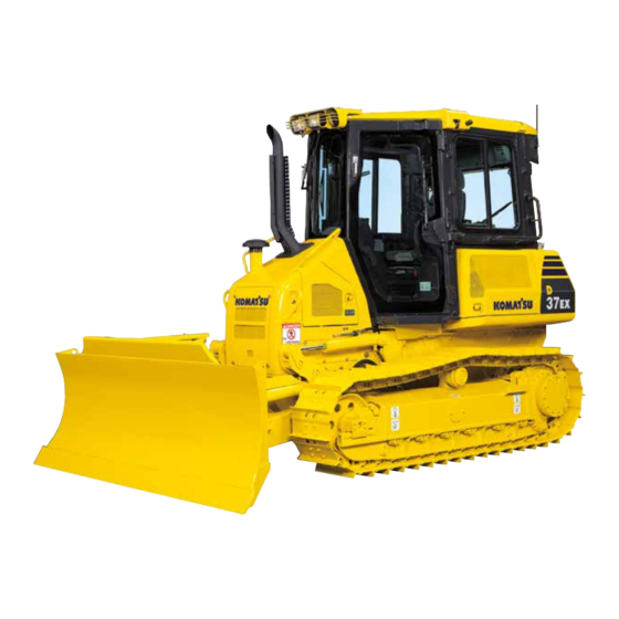
OPERATION GENERAL VIEW GENERAL VIEW GENERAL VIEW OF MACHINE Machine equipped with ROPS cab Machine equipped with ROPS canopy Blade Track frame Angle cylinder Lift cylinder Front cover Idler Cab (with ROPS) (10) Work equipment frame Track shoe (11) ROPS canopy Sprocket (12) Rear mask... -
Page 52: General View Of Controls And Gauges
OPERATION GENERAL VIEW GENERAL VIEW OF CONTROLS AND GAUGES 3 - 3... - Page 53 OPERATION GENERAL VIEW Steering, forward-reverse, gear shift lever (15) Blower selector switch Blade control lever (machines equipped with cab) Lamp switch (16) Temperature control switch Fan operation confirmation switch (machines equipped with cab) Buzzer cancel switch (17) Accessory socket (machines equipped with cab) Information switch (if equipped) Monitor panel...
- Page 54 OPERATION GENERAL VIEW MONITOR PANEL Engine coolant temperature gauge HST charge pressure caution lamp Hydraulic oil temperature gauge (10) Engine coolant temperature caution lamp Display panel A (speed range, shift mode (11) Fan operating confirmation lamp indicator) (12) Water separator caution lamp Fuel level gauge (13) Maintenance caution lamp...
-
Page 55: Explanation Of Components
OPERATION EXPLANATION OF COMPONENTS EXPLANATION OF COMPONENTS The following is an explanation of devices needed for operating the machine. To perform suitable operations correctly and safely, it is important to completely understand methods of operating the equipment, and the meanings of the displays. FRONT PANEL Emergency caution items Lamps... - Page 56 Stop the engine, then turn the starting switch to the ON position and check that the lamps light up for approx. 2 seconds. If they do not light up, please ask your Komatsu distributor to carry out inspection. When carrying out the checks before starting, use the monitor system check.
- Page 57 OPERATION EXPLANATION OF COMPONENTS EMERGENCY CAUTION ITEMS CAUTION If any of the caution lamps begins to flash, stop the engine or reduce the engine speed to low idle immediately and check the trouble spot for necessary actions. These items must be monitored when the engine is running. If there is any problem, the caution lamp for the location of the problem and warning lamp (A) flash, and the alarm buzzer sounds intermittently.
- Page 58 OPERATION EXPLANATION OF COMPONENTS HYDRAULIC OIL TEMPERATURE CAUTION LAMP This lamp (2) warns the operator that the hydraulic oil temperature has risen. If it flashes, run the engine at low idling until the hydraulic oil temperature gauge displays the green range. ENGINE OIL PRESSURE CAUTION LAMP This lamp (3) warns the operator that the engine lubricating oil pressure has dropped.
- Page 59 OPERATION EXPLANATION OF COMPONENTS CAUTION ITEMS CAUTION If these caution lamps flash, check and repair the appropriate location as soon as possible. These are items which need to be observed when the engine is running. If any problem occurs, the item needing immediate repair is displayed.
- Page 60 OPERATION EXPLANATION OF COMPONENTS BATTERY CHARGE CIRCUIT CAUTION LAMP This lamp (2) flashes while the engine is running to warn the operator that charging is not being carried out properly. If it flashes, stop the engine, and check for any loose alternator V-belt.
- Page 61 OPERATION EXPLANATION OF COMPONENTS METER GROUP Engine coolant temperature gauge Display panel A (speed range, shift mode Hydraulic oil temperature gauge indicator) Fuel level gauge Display panel B (multi-information) Engine pre-heating pilot lamp ENGINE COOLANT TEMPERATURE GAUGE NOTICE If the coolant temperature gauge often enters red range (C), check the radiator for clogging. Gauge (1) indicates temperature of the engine coolant.
- Page 62 OPERATION EXPLANATION OF COMPONENTS HYDRAULIC OIL TEMPERATURE GAUGE NOTICE If the hydraulic oil temperature gauge tends to enter red range (C), check for clogging of the oil cooler. This meter (2) displays the oil temperature in the pump suction piping. Green range (B) should be lighted up during normal operations.
- Page 63 OPERATION EXPLANATION OF COMPONENTS DISPLAY PANEL A (SPEED RANGE, SHIFT MODE INDICATOR) This meter (5) displays the speed range and shift mode. Use the shift mode switch to switch the shift mode. Position (A): Quick shift mode Pilot lamp (C) on display panel A lights up. Position (B): Variable shift mode Pilot lamp (D) on display panel A lights up.
- Page 64 OPERATION EXPLANATION OF COMPONENTS QUICK SHIFT MODE The travel speed is set to the travel speed that matches the general operating load. Operation is easy: each time the shift switch on the steering, forward-reverse, gear shift lever is pressed, the speed switches 1st ↔ 2nd ↔ 3rd.
- Page 65 OPERATION EXPLANATION OF COMPONENTS VARIABLE SHIFT MODE (CONTINUOUSLY VARIABLE SHIFT MODE) The travel speed can be set in 20 stages from 0.8 km/h (0.5 MPH) to 8.5 km/h (5.3 MPH). In particular, the minimum travel speed is set low so that work such as loading the machine onto a trailer or traveling over rough places on the road surface can be carried out more safely.
- Page 66 OPERATION EXPLANATION OF COMPONENTS REVERSE TRAVEL SPEED INDICATOR It is possible to set the reverse travel speed by selecting one of the following 5 speed ranges. The speed ranges have the following ratio to the forward travel speed. (1) Approx. 20% slower than forward travel speed (2) Same as forward travel speed (3) Approx.
- Page 67 OPERATION EXPLANATION OF COMPONENTS DISPLAY PANEL B (multi-information) The top and bottom lines in display panel B (multi-information) display information related to the condition of the machine. The content of the display is divided into "OPERATING MODE" and "MAINTENANCE MODE". Use the buzzer cancel switch to switch between the operating mode and maintenance mode.
- Page 68 OPERATION OPERATION EXPLANATION OF COMPONENTS EXPLANATION OF COMPONENTS Maintenance mode This displays various types of information related to maintenance of the machine. For details, see "METHOD OF USING MAINTENANCE MODE (PAGE 3-27)". 3 - 19...
- Page 69 If the display does not go out even when the filter is replaced, there is probably a different cause of the failure, so have inspection carried out. Please ask your Komatsu distributor to carry out the inspection. When the filter is replaced or when the fuel tank runs out of fuel, and operation of the priming pump sends air to the fuel line, failure codes CA559 or CA2249 may be displayed, but this does not indicate an abnormality.
- Page 70 OPERATION EXPLANATION OF COMPONENTS LAMPS Warning lamp Fan operation confirmation lamp WARNING LAMP (Red) NOTICE If alarm buzzer sounds, stop work immediately and perform inspection and maintenance of the appropriate point. This lamp (1) flashes when caution lamp (A) flashes and an action code is displayed on the top line of display panel B (multi-information).
- Page 71 OPERATION EXPLANATION OF COMPONENTS FAN OPERATION CONFIRMATION LAMP This lamp (2) lights up or flashes according to the following operations. After the starting switch is turned ON, if this lamp (2) is out and the engine is started, the fan will rotate in the normal direction. After the starting switch is turned ON, if the side of the fan rotation selector switch is pressed, this lamp (2) lights up.
-
Page 72: Switches
OPERATION EXPLANATION OF COMPONENTS SWITCHES Lamp switch Starting switch Buzzer cancel switch Fan rotation selector switch Information switch Foot heater switch Reverse travel speed setting switch (Standard for machines equipped with cab) Shift mode switch (Optional for machines equipped with canopy) LAMP SWITCH Use this switch (1) to light up the front and rear lamps. - Page 73 OPERATION EXPLANATION OF COMPONENTS BUZZER CANCEL SWITCH This switch (2) is used to operate control panel B (multi-information) or to stop the alarm buzzer. When the switch is released, it returns automatically to the center position. When display panel B (multi-information) is in the operating mode If the warning buzzer is sounding, press the side of this...
- Page 74 OPERATION EXPLANATION OF COMPONENTS SHIFT MODE SWITCH Use switch (5) to change the shift mode. For details, see "DISPLAY PANEL A (SPEED RANGE, SHIFT MODE INDICATOR) (PAGE 3-14)". When the switch is released, it returns automatically to the center position. STARTING SWITCH The switch (6) is used to start and stop the engine.
- Page 75 OPERATION EXPLANATION OF COMPONENTS FAN ROTATION SELECTOR SWITCH Use this switch (7) to change the direction of rotation of the cooling fan. When the switch (7) is released, it automatically returns to the center position. Position : Normal rotation Normally, use the switch at this position. Fan operation confirmation lamp (A) is OFF at this position.
- Page 76 OPERATION EXPLANATION OF COMPONENTS METHOD OF USING MAINTENANCE MODE To switch from the operation mode to the maintenance mode, press the portion of the buzzer cancel switch. The mode will switch to the maintenance mode. At first, the oil and filter maintenance mode is displayed. EXPLANATION OF MODES AND OPERATION There are 2 types of sub mode in the maintenance mode.
- Page 77 OPERATION EXPLANATION OF COMPONENTS METHOD OF SELECTING EACH MODE 3 - 28...
- Page 78 This function is only a guideline. If dirty oil or filters are found during daily maintenance, replace them immediately. If the controllers or monitor panel are replaced, the timer for this function will not work properly. Contact your Komatsu distributor for replacement.
- Page 79 OPERATION EXPLANATION OF COMPONENTS METHOD OF USING USER ADJUST MODE With the user adjust mode, the brightness of the panel screen backlighting and the contrast of the liquid crystal panel can be changed. 1. Adjusting backlighting of liquid crystal display 1) The figure on the right shows the mode for adjusting the backlighting of the liquid-crystal gauge.
- Page 80 OPERATION EXPLANATION OF COMPONENTS 2. Adjusting backlighting of display panel B (multi-information) 1) The figure on the right shows the mode for adjusting the backlighting of display panel B (multi-information). On this screen, press the position of the buzzer cancel switch to switch to the screen for adjusting the brightness.
- Page 81 OPERATION EXPLANATION OF COMPONENTS 3. Adjusting contrast of liquid crystal display panel B (multi-information) 1) The figure on the right shows the mode for adjusting the contrast of display panel B (multi-information). On this screen, press the position of the buzzer cancel switch to switch to the screen for adjusting the contrast.
- Page 82 OPERATION EXPLANATION OF COMPONENTS SWITCHES Fuel control dial Accessory socket (machines equipped with cab) Horn switch (if equipped) Room lamp switch (machines equipped with cab) Air conditioner switch Wiper switch (machines equipped with cab) (machines equipped with cab) Cigarette lighter (machines equipped with cab) 3 - 33...
- Page 83 OPERATION EXPLANATION OF COMPONENTS FUEL CONTROL DIAL WARNING When the machine is stopped, check that the steering, directional, and gear shift lever is at the Neutral position before turning the fuel control dial to the FULL position. If the steering, directional, and gear shift lever is at a forward or reverse travel position and the fuel control dial is turned to the FULL position, there is danger that the machine may suddenly move and cause serious personal injury.
- Page 84 OPERATION EXPLANATION OF COMPONENTS WIPER SWITCH (Machine equipped with cab) This (4) activates the wipers. The wiper switches are as follows: (A): Left door window (B): Front window (C): Right door window (D): Rear window (E): Intermittent switch (for left and right door windows) The wiper will automatically stop if the blade is stuck for some reason.
- Page 85 OPERATION OPERATION EXPLANATION OF COMPONENTS EXPLANATION OF COMPONENTS Wiper intermittent switch (for left and right door windows) If the switch is set to ON position (J) to operate the wiper, the wiper will perform 1 cycle every 4 seconds. REMARK When the intermittent switch is at ON position (J), if the wiper switch for the left and right door windows is turned ON, the wiper will move intermittently.
-
Page 86: Control Levers And Pedals
OPERATION EXPLANATION OF COMPONENTS CONTROL LEVERS AND PEDALS Work equipment lock lever Brake pedal Parking brake lever Decelerator pedal Steering, forward-reverse, gear shift lever Blade control lever 3 - 37... - Page 87 OPERATION EXPLANATION OF COMPONENTS WORK EQUIPMENT LOCK LEVER WARNING When leaving the operator's compartment, set the work equipment lock lever securely to the LOCK position. If the work equipment lock lever is not at the LOCK position and the control levers are touched by mistake, it may lead to serious personal injury.
- Page 88 OPERATION EXPLANATION OF COMPONENTS STEERING, FORWARD-REVERSE, GEAR SHIFT LEVER This control lever (3) serves to change forward or reverse direction of machine travel, steer the machine to the right or left, change the traveling speed and make a counter-rotation. Forward-reverse shifting Position (A): FORWARD Position (B): REVERSE Position (N): Neutral...
- Page 89 OPERATION EXPLANATION OF COMPONENTS BRAKE PEDAL When this pedal (4) is depressed, the travel speed is reduced according to the amount the pedal is depressed. When the operating effort becomes stronger, the machine stops. If the brake pedal is depressed further, the mechanical brake is applied.
- Page 90 OPERATION EXPLANATION OF COMPONENTS BLADE CONTROL LEVER This lever (6) is used to lift, tilt or angle the blade. LIFTING CONTROL (A) RAISE: Blade goes up (B) HOLD: Blade stops and is held in position (C) LOWER: Blade goes down (D) FLOAT: Blade moves freely under external force REMARK When released from FLOAT position, this lever will not return to...
- Page 91 OPERATION EXPLANATION OF COMPONENTS ANGLING CONTROL Rotate the knob to the left or right to change the angle of the blade. (G) Angle to left (B) HOLD: Blade stops and is held in position (H) Angle to right REMARK When performing only angling operation, be sure to set the lever in the neutral (HOLD) position and turn the knob to the right or left.
-
Page 92: Fuse
OPERATION EXPLANATION OF COMPONENTS FUSE NOTICE Before replacing a fuse, be sure to turn starting switch to the OFF position. Fuses protect the wiring and electrical components from burning out. If a fuse is corroded or covered in white powder, or if there is any looseness between the fuse holder and the fuse, replace the fuse. - Page 93 OPERATION EXPLANATION OF COMPONENTS FUSE CAPACITY AND CIRCUIT NAME Chassis Fuse box (1) Fuse Name of circuit capacity Lamp Horn PPC lock Air conditioner power source Machine controller 1 Center brake Cab power source 1 Cab power source 2 Starting switch Engine controller 1 Power takeoff port Preheater relay...
-
Page 94: Electric Power Take-Out Adapter
OPERATION EXPLANATION OF COMPONENTS ELECTRIC POWER TAKE-OUT ADAPTER NOTICE Do not use the cigarette lighter as a power supply for 12V equipment. This may cause the equipment to break down. When using the cigarette lighter socket as a power takeoff port, to install equipment that exceeds 120W (24V x 5A). (Machine equipped with cab) (If equipped) Accessory socket (A) can be used for 12V low-voltage equipment. -
Page 95: Door - Open Lock
OPERATION EXPLANATION OF COMPONENTS DOOR - OPEN LOCK (Machine equipped with cab) Use this when your want to keep the door held open. 1. Push the door against the door catch (1). The door will be held by the door catch. 2. -
Page 96: Cover, Cap With Lock
OPERATION EXPLANATION OF COMPONENTS COVER, CAP WITH LOCK Use the starting key to lock or unlock the covers and caps with locks. (A separate key is used for locking the fuel tank cap.) For details of the locations of the covers and caps with locks, see "LOCKING (PAGE 3-109)". - Page 97 OPERATION EXPLANATION OF COMPONENTS METHOD OF OPENING OR CLOSING THE FUEL TANK CAP The method of opening or closing the fuel tank cap is as follows. OPENING THE CAP 1. Raise lever (1) in the (a) direction. 2. When lever (1) is turned in the (c) direction (counterclockwise) by approx 35°, it stops at the stopper, and the cap can be opened.
- Page 98 OPERATION EXPLANATION OF COMPONENTS METHOD OF OPENING OR CLOSING COVER WITH LOCK WHEN OPENING (IF IT IS LOCKED) 1. Insert the key in the slot. 2. Turn the key counterclockwise in direction (A), then pull the cover knob to open the cover. WHEN LOCKING 1.
-
Page 99: Opening Or Closing Rear Mask
OPERATION EXPLANATION OF COMPONENTS OPENING OR CLOSING REAR MASK WARNING Stop the engine and fan before opening or closing the rear mask. If you touch the fan when it is rotating, it may cause serious personal injury. When opening or closing the rear mask, be careful not to get your fingers caught by the tank. After opening the rear mask, check that the lock is applied securely. -
Page 100: Door Pocket
OPERATION EXPLANATION OF COMPONENTS DOOR POCKET There is a pocket on the back of the operator's seat. (fitted with a lock) Keep the Operation & Maintenance manual in this pocket so that the operator can read it whenever necessary. REMARK When locking the machine with the canopy specification, use the hole at the entrance of the pocket. -
Page 101: Cup Holder
OPERATION EXPLANATION OF COMPONENTS CUP HOLDER This is the place to put cans and cups. If cans or cups are put in any other place when they still have drink remaining in them, there is danger that they will fall over and that the drink will get over the surrounding area or equipment. -
Page 102: Car Radio, Handling
OPERATION EXPLANATION OF COMPONENTS CAR RADIO, HANDLING (Machine equipped with cab) (If equipped) EXPLANATION OF COMPONENTS Power switch/volume Cassette door Auto-store/preset scan button Fast forward, rewind buttons Bass control knob (10) Preset buttons Treble control knob (11) Metal tape button Loudness button (12) Manual tuning buttons... - Page 103 OPERATION EXPLANATION OF COMPONENTS POWER SWITCH/VOLUME Turn this knob (1) to the right until it clicks to turn the power on. Turn it further to increase the volume. AUTO-STORE/PRESET SCAN BUTTON Use this button (2) to actuate the preset scan and auto-store functions.
- Page 104 OPERATION EXPLANATION OF COMPONENTS TREBLE CONTROL KNOB Turn this button (4) to the left to reduce the low tones; turn it to the right to emphasize the high tones. Direction (a): High tone reduced Direction (b): High tone emphasized LOUDNESS BUTTON This button (5) is used when playing at low volume.
- Page 105 OPERATION EXPLANATION OF COMPONENTS TAPE EJECT BUTTON This button (7) is used to stop the tape and to eject the cassette. When this button is pressed, the tape is ejected and the radio plays. CASSETTE DOOR Set the cassette with the exposed portion of the tape on the right side and insert it through the cassette door (8).
- Page 106 OPERATION EXPLANATION OF COMPONENTS METAL TAPE BUTTON (used also for preset button No. 5) This button (11) is used when playing a metal or chrome tape. This button is also used for preset button No. 5. When it is pressed, "MTL"...
- Page 107 OPERATION EXPLANATION OF COMPONENTS METHOD OF OPERATION WHEN PRESETTING STATIONS It is possible to preset 6 MW (AM) stations and 12 FM stations (FM1: 6 stations, FM2: 6 stations). REMARK If you are playing the cassette, press the tape eject button to stop the tape. PROCEDURE FOR SUTOMATIC PRESETTING 1.
- Page 108 OPERATION EXPLANATION OF COMPONENTS LISTENING TO RADIO 1. Turn the starting switch ON, then turn power switch (1) ON. 2. Use band selector button (2) to select MW (AM), FM1 or FM2. 3. Select the station with the preset buttons (3). REMARK If you do not know what station has been recorded for any preset button, press auto store/preset scan button (4) for less than 0.5...
- Page 109 If the sound cannot be heard, nothing is displayed, or any other problem occurs, turn off the power switch and ask your Komatsu distributor to make repairs without delay. Stow the antenna when traveling in places with low overhead clearance.
-
Page 110: Air Conditioner, Handling
OPERATION EXPLANATION OF COMPONENTS AIR CONDITIONER, HANDLING (Machine equipped with cab) EXPLANATION OF PARTS Air conditioner mode selector switch (3) Temperature control switch Blower selector switch AIR CONDITIONER MODE SELECTOR SWITCH Use this switch (1) to switch the air conditioner mode. Position (A): Cooler/air conditioner system Cooling can be carried out. - Page 111 OPERATION EXPLANATION OF COMPONENTS TEMPERATURE CONTROL SWITCH Use this switch (3) to adjust the cooling or heating temperature. If the dial is turned to the left (counterclockwise in direction C), the temperature of the air coming from the vents becomes lower. If the dial is turned to the right (clockwise in direction H), the temperature of the air coming from the vents becomes higher.
- Page 112 OPERATION EXPLANATION OF COMPONENTS PRECAUTION WHEN USING AIR CONDITIONER CARRY OUT VENTILATION FROM TIME TO TIME WHEN USING THE COOLER If you smoke when the cooler is on, the smoke may start to hurt your eyes, so turn the lever to FRESH to remove the smoke while continuing the cooling.
-
Page 113: Operation
Check carefully, and if any problem is found, always carry out repairs or contact your Komatsu distributor. Not to get up or down at the rear of the machine. It is dangerous because it is easy to slip, and also this area cannot be seen from the operator's seat. - Page 114 11. Check drawbar and hook If any problem is found, ask your Komatsu distributor to carry out repairs. 12. Remove mud from under work equipment hoses Check that there is no mud or soil accumulated under the hoses from the mainframe to the work equipment frame.
- Page 115 OPERATION OPERATION CHECK BEFORE STARTING Always check the items in this section before starting the engine each day. CHECK COOLANT LEVEL, ADD COOLANT WARNING Do not open the radiator cap unless necessary. When checking the coolant, always wait for the engine to cool down and check the sub-tank.
- Page 116 For details, see "CHECK MONITOR SYSTEM (PAGE 3-7)". REMARK If the lamps do not light up, there may be a failure or disconnection in the monitor, please contact your Komatsu distributor. CHECK FUEL LEVEL, ADD FUEL WARNING When adding fuel, never spill the fuel or let it overflow. It will cause fire.
- Page 117 OPERATION OPERATION CHECK OIL LEVEL IN ENGINE OIL PAN, ADD OIL WARNING Parts and oil are at high temperature immediately after the engine is stopped and may cause serious burns. Wait for the oil temperature to go down before performing this operation. NOTICE Do not move the blade when the front cover and engine side cover on the left side of the machine are open.
- Page 118 OPERATION OPERATION OPERATION OPERATION 5. If the oil is above the H mark, remove covers (2) and (3) under the front cover and prepare a container to catch the drained oil. 6. Loosen drain plug (P), drain the excess oil, then tighten drain plug (P).
- Page 119 OPERATION OPERATION CHECK ADDITIONAL WATER SEPARATOR, DRAIN WATER (ONLY POOR FUEL ARRANGEMENT SPECIFICATION) WARNING The engine fuel piping system is under high internal pressure when the engine is running. Always reduce the internal pressure before draining water or replacing the element cup. Do not bring fire close.
- Page 120 OPERATION OPERATION OPERATION OPERATION 2. Check if there is any water accumulated in water separator (4). 3. If there is any water accumulated, loosen air bleeding plug (5) (width across flats: 13 mm (0.5 in)), then loosen drain valve (6) of the water separator and drain the water.
- Page 121 OPERATION OPERATION CHECK WATER SEPARATOR, DRAIN WATER AND SEDIMENT NOTICE Do not move the blade when the front cover and engine side cover on the left side of the machine are open. The blade will hit the covers and there is danger that the covers may be broken. 1.
- Page 122 OPERATION OPERATION OPERATION OPERATION If the movement of drain valve (4) has becomes stiff, coat O-ring portion (5) of the drain valve with grease to make the valve move more smoothly. REMARK When closing the valve, be careful not to get grease on discharge port (6) and thread (7) of the valve.
- Page 123 OPERATION OPERATION CHECK OIL LEVEL IN HYDRAULIC TANK, ADD OIL WARNING Immediately after the engine is stopped, the parts and the oil are at a high temperature. Wait for the temperature to go down before starting the operation. When the cap of the oil filler port is removed, oil may spurt out, so turn the cap slowly to release the internal pressure, then remove it carefully.
- Page 124 Be particularly careful when inspecting the wiring of the battery. Always check that there is no flammable material accumulated around the battery. Remove any such flammable material. Please consult your Komatsu distributor when carrying out investigation and repair of the cause. 3 - 75...
- Page 125 Check that the head lamp, rear lamp, and instrument lamp light up normally and they are free from stain and damage. If the lamps do not light, check for a broken bulb or disconnected wire, contact your Komatsu distributor for repairs. 1. Turn the starting switch to the ON position.
- Page 126 OPERATION CHECK OF OPERATION OF BACKUP ALARM Check that the backup alarm sounds normally. If it does not, a defect or broken wire is suspected, ask your Komatsu distributor for possible repairs. 1. Turn the starting switch to the ON position.
- Page 127 OPERATION OPERATION ADJUSTMENT ADJUST OPERATOR'S SEAT WARNING When adjusting the position of the operator's seat, always set the work equipment lock lever to the LOCK position to prevent any accidental contact with the control levers. Always adjust the operator's seat before starting each operation or when the operators change shift. When adjusting the seat, put your back against the backrest and adjust to a position where the brake pedal can be fully depressed.
- Page 128 OPERATION OPERATION (E) Seat height adjustment Pull up levers (4) and (5) alternately to adjust the angle of the seat. Then, release the levers to lock the seat. (Height adjustment distance: 5 stages, 60 mm (2.4 in)) ADJUST ARMREST The height of the armrests on both sides of the operator's seat can be adjusted to three levels.
- Page 129 OPERATION OPERATION FASTENING AND REMOVING SEAT BELT Always install a seat belt on machines equipped with ROPS. WARNING Before fitting the seat belt, check that there is no problem in the mounting bracket and mounting belt of the belt. If the belt is worn or damaged, replace it.
- Page 130 OPERATION OPERATION ADJUST MIRROR WARNING Be sure to adjust the mirrors before starting work. If they are not adjusted properly, you cannot secure the visibility and may be injured or may injure someone seriously. Loosen nut (1) installing the mirror, then adjust the position so that it gives the best view from the operator's seat.
- Page 131 OPERATION OPERATION OPERATION AND CHECK BEFORE STARTING ENGINE WARNING When starting the engine, check that the work equipment lock lever are placed securely at the LOCK position. If the work equipment control lever is touched by accident when the engine is started, the work equipment may move unexpectedly and cause serious injury or damage.
- Page 132 OPERATION OPERATION OPERATION OPERATION 4. Check that the blade control lever (4) is HOLD position (H). 3 - 83...
-
Page 133: Starting Engine
OPERATION OPERATION STARTING ENGINE NORMAL STARTING WARNING Sit down in the operator's seat before starting the engine. Do not attempt to start the engine by short-circuiting the engine starting circuit. Such an act may cause serious bodily injury or fire. Check that there are no persons or obstacles in the surrounding area, then sound the horn and start the engine. - Page 134 OPERATION OPERATION OPERATION OPERATION 4. After the engine starts, release the key in the starting switch. The key will automatically return to the ON position. 5. Keep the engine idle for the initial 15 seconds right after it has been started, and do not operate any control lever or the fuel adjustment dial during that time.
- Page 135 OPERATION OPERATION STARTING IN COLD WEATHER WARNING Start the engine only after sitting down in the operator's seat. Do not attempt to start the engine by short-circuiting the engine starting circuit. Such an act may cause a serious bodily injury or fire. Check that there are no persons or obstacles in the surrounding area, then sound the horn and start the engine.
- Page 136 OPERATION OPERATION OPERATION OPERATION 4. Check that engine pre-heating pilot lamp (3) on the monitor panel lights up. 5. Maintain the key in the on position until the pre-heating pilot lamp (3) goes off. 6. When preheating pilot lamp (3) goes out, turn the key in starting switch (2) to the START position and start the engine.
- Page 137 OPERATION OPERATION Turbo protect function The turbo protect function is a function to protect the turbocharger by keeping the engine speed at less than 1000 rpm immediately after the engine is started. When the turbo protect function is actuated, the engine speed is held at less than 1000 rpm, even if the fuel control dial is operated.
-
Page 138: Operations And Checks After Starting Engine
BREAKING IN THE NEW MACHINE CAUTION Your Komatsu machine has been thoroughly adjusted and tested before shipment. However, operating the machine under severe conditions at the beginning can adversely affect the performance and shorten the machine life. Be sure to break-in the machine for the initial 100 hours (as indicated by the service meter). - Page 139 (2) is in green range (B). (A): White range (B): Green range (C): Red range 3. Check for abnormal exhaust gas color, noise, or vibration. If any problem is found, contact your Komatsu distributor. 3 - 90...
- Page 140 OPERATION OPERATION STARTING IN COLD WEATHER (Ambient temperature below 10°C (50°F)) NOTICE Do not carry out operations or operate the levers suddenly when the hydraulic oil is at low temperature. Always carry out the warming-up operation. This will also extend the service life of the machine. Do not suddenly accelerate the engine before the warming-up operation is completed.
- Page 141 (A). 5. Check for abnormal exhaust gas color, noise, or vibration. If any problem is found, contact your Komatsu distributor. 6. After carrying out the warming-up operation, to make the temperature of all equipment the same, run the engine at a mid-range speed and travel slowly forward and in reverse.
-
Page 142: Stopping Engine
OPERATION OPERATION STOPPING ENGINE NOTICE If the engine is stopped without allowing it to cool down, there is danger that the service life of various parts of the engine will be reduced. Except in emergencies, never stop the engine suddenly. If the engine overheats, do not stop it suddenly. -
Page 143: Machine Operation
OPERATION OPERATION MACHINE OPERATION MOVING MACHINE WARNING When starting the machine off, check that the area around the machine is safe and sound the horn before moving. Do not allow anybody to enter the area around the machine. The area behind the machine is a blind spot, so be particularly careful when driving in reverse. - Page 144 Check that the alarm sounds when the steering, forward-reverse, gear shift lever is operated to the REVERSE position. If the alarm does not sound, ask your Komatsu distributor to carry out repairs. 7. Turn fuel control dial (3) in the full speed (MAX) direction.
- Page 145 OPERATION OPERATION OPERATION OPERATION 8. Release decelerator pedal (5) slowly and move the machine off. REMARK When the machine starts off, it may deviate slightly, but this is caused by the actuation of the straight-line compensation system. It does not indicate any abnormality. 3 - 96...
- Page 146 OPERATION OPERATION STOPPING MACHINE WARNING Avoid stopping suddenly. Give yourself ample room when stopping. 1. Depress decelerator pedal (1), return steering, forward-reverse, gear shift lever (2) to the N position, and stop the machine. If the machine is to be kept in a stopped condition, depress brake pedal (3).
-
Page 147: Shifting Gears
OPERATION OPERATION SHIFTING GEARS The machine does not have to be stopped to shift gears. Press the shift switch on the knob of steering, forward-reverse, gear shift lever (1) and select the desired speed range. Gear shifting Press the shift switch of the knob of the steering, forward-reverse, gear shift lever to carry out the gearshifting operation. -
Page 148: Shifting Between Forward And Reverse
Check that the alarm sounds when the steering, forward-reverse, gear shift lever is operated to the REVERSE position. If the alarm does not sound, ask your Komatsu distributor to carry out repairs. 3. Release decelerator pedal (1) and raise the engine speed. -
Page 149: Steering Machine
OPERATION OPERATION STEERING MACHINE WARNING Avoid as much as possible turning the machine on a slope. The machine will tend to slip sideways. Particular care should be taken on soft or clay soil. Never make a pivot turn at high speed. NORMAL TURNING turn machine... - Page 150 OPERATION OPERATION WHEN MAKING PIVOT TURN TO LEFT WHILE TRAVELING When steering the machine, if the lever is operated further from the position where it becomes heavy, the left and right tracks will rotate in opposite directions and the machine will carry out a counterrotation turn.
-
Page 151: Precautions For Operation
OPERATION OPERATION PRECAUTIONS FOR OPERATION PAY ATTENTION TO GAUGES If the hydraulic oil temperature gauge reaches the red range during operations, reduce the operating load and wait for the temperature to go down. PERMISSIBLE WATER DEPTH When operating in water, always keep the bottom of carrier rollers (1) above the surface of the water. - Page 152 OPERATION OPERATION PRECAUTIONS FOR BLIND SPOTS CAUSED BY CAB STAY (Machine equipped with cab) WARNING The cab stays create blind spots. When operating, check carefully that there is no person or obstacle in the surrounding area. 3 - 103...
-
Page 153: Work Possible Using Bulldozer
OPERATION OPERATION WORK POSSIBLE USING BULLDOZER In addition to the following, it is possible to further increase the range of applications by using various attachments. DOZING A bulldozer digs and transports dirt in a forward direction. Slope excavation can always be most effectively carried out by proceeding from the top downward. - Page 154 OPERATION OPERATION CUTTING INTO HARD OR FROZEN GROUND OR DITCHING For digging and ditch excavation of hard or frozen ground, tilt the blade. Even hard ground can be dug effectively by a tilted or angled blade. FELLING TREES, REMOVING STUMPS NOTICE Do not uproot trees or stumps or fell trees by angling or tilting the blade.
-
Page 155: Adjusting Posture Of Work Equipment
OPERATION OPERATION ADJUSTING POSTURE OF WORK EQUIPMENT For details of the procedure for adjusting play in the center ball, see the "ADJUST PLAY IN CENTER BALL (PAGE 4-45)" in the MAINTENANCE Section and WHEN REQUIRED Section. ADJUST ANGLE OF BLADE EDGE WARNING It is dangerous if the work equipment moves by accident when then angle of the blade edge is being adjusted. - Page 156 OPERATION OPERATION REMARK When the maximum cutting angle (blade tilted fully forward) is changed to the minimum cutting angle (blade tilted back), there is resistance from the pressure stored in the angle cylinder, so the operating effort may gradually become heavier. In this case, turn the starting switch ON (there is no need to start the engine), then release the work equipment lock lever and operate the blade control lever to the Angle position to release the pressure in the angle cylinder.
-
Page 157: Parking Machine
OPERATION OPERATION PARKING MACHINE WARNING When parking the machine, select flat hard ground. Avoid parking the machine on a slope. On slopes, even if steering, forward-reverse, gear shift lever is set to the N position, the machine may move slowly down the slope. If it is unavoidably necessary to park the machine on a slope, place the parking brake lever at the LOCK position and insert blocks under the track shoes. -
Page 158: Check After Finishing Work
OPERATION OPERATION CHECK AFTER FINISHING WORK BEFORE STOPPING ENGINE Use the meters and caution lamps to check the engine water temperature, engine oil pressure, fuel level, and hydraulic oil temperature. AFTER STOPPING ENGINE 1. Walk around the machine and check the work equipment, machine exterior, and undercarriage, also check for any leakage of oil or coolant. - Page 159 OPERATION OPERATION OPERATION OPERATION Places locked with special key Fuel tank cap (8) REMARK If the padlock (A) is to be used, it is recommended to use the type that has the cover to protect the key hole. For details of the method of locking, see "COVER, CAP WITH LOCK (PAGE 3-47)". 3 - 110...
-
Page 160: Tips For Longer Undercarriage Life
OPERATION METHOD Select the track shoe that best suits the type of soil to be encountered in service. Please consult your Komatsu distributor when selecting track shoes. Do not allow shoe slipping to occur during operation. If shoe slipping occurs, reduce load on the blade until slipping stops. - Page 161 Frequent inspection and prompt repair will reduce repair costs. The following items for inspection will serve as a guide to maintenance service of each undercarriage part. Perform periodical inspection and contact the Komatsu distributor in your area when machine has approached repairable limits and reversing limits.
- Page 162 OPERATION OPERATION MEASURING OUTSIDE DIAMETER OF TRACK ROLLER 1. Measure the height (dimension C) of the link tread as shown in the diagram. 2. Stop machine at position where link tread, whose size C has been measured completely, contacts roller tread. Then measure size B.
-
Page 163: Transportation
REMOVING CAB The cab forms one unit with the operator's seat, so it cannot be removed. If there is any problem when transporting, please consult your Komatsu distributor. PRECAUTIONS WHEN REMOVING WORK EQUIPMENT 1. Lower the blade to the ground and set it horizontal to the ground surface. -
Page 164: Loading, Unloading Work
OPERATION TRANSPORTATION LOADING, UNLOADING WORK WARNING Since loading and unloading of the machine is dangerous, be extremely careful. When loading or unloading the machine, operate it slowly with the engine speed low and the transmission in the 1st gear. Use ramps having sufficient width, length, thickness, and strength. Install them securely and set their angle to 15° or less. If the ramps are deflected appreciably, reinforce them with blocks. - Page 165 OPERATION TRANSPORTATION SECURING MACHINE WARNING When the edge of the blade protrudes beyond the trailer, angle the blade. NOTICE Stow the radio antenna. Load the machine onto a trailer as follows: 1. Lower the work equipment slowly. 2. Set the work equipment lock lever to the LOCK position (L) securely.
- Page 166 OPERATION TRANSPORTATION UNLOADING WORK 1. Load and unload on firm level ground only. Maintain a safe distance from the edge of a road. 2. Apply the trailer brakes securely and put blocks (1) under the tires to hold the trailer in position.Set gap (3) between ramps (2) to match the distance between the left and right tracks, and keep angle (4) to a maximum of 15°.
-
Page 167: Method Of Lifting Machine
This method of lifting applies to the standard specification machine. The method of lifting differs according to the attachments and options installed. For details of the procedure for machines that are not the standard specification, please consult your Komatsu distributor. For weight, see "SPECIFICATIONS (PAGE 5-2)". - Page 168 OPERATION TRANSPORTATION PROCEDURE FOR LIFTING OPERATIONS When lifting the machine, stop it on a level place, then observe the following procedure. 1. Set the work equipment lock lever to the LOCK position (L) securely. 2. Stop the engine and set the parking brake lever to the LOCK position (L).
-
Page 169: Cold Weather Operation
Antifreeze is flammable. Do not bring any flame close. Do not smoke when handling antifreeze. NOTICE Please use Komatsu genuine supercoolant (AF-NAC) for the coolant. As a basic rule, we do not recommend the use of any coolant other than Komatsu genuine supercoolant. -
Page 170: After Completion Of Work
OPERATION COLD WEATHER OPERATION BATTERY WARNING The battery generates flammable gas. Do not bring fire or sparks near the battery. Battery electrolyte is dangerous. If it gets in your eyes or on your skin, wash it off with a large amount of water and consult a doctor. -
Page 171: Long-Term Storage
Set all the control levers to the Neutral position or HOLD position, then set the work equipment lock lever and parking brake lock lever to the LOCK position. To prevent rust, fill with Komatsu genuine supercoolant (AF-NAC) to give a density of at least 30% for the engine coolant. -
Page 172: Troubleshooting
To move the machine in this case, the oil pressure in the brake circuit must be heightened to the specified level with a special device. Ask your Komatsu distributor. When towing a machine, travel at a speed of less than 1 km/h for a distance of only a few meters to a place that is suitable for carrying out repairs. - Page 173 OPERATION OPERATION TROUBLESHOOTING TROUBLESHOOTING If the machine gets stuck in the mud or a heavy thing needs to be towed, install a towing wire rope to the draw bar pin. 3 - 124...
-
Page 174: If Battery Is Discharged
OPERATION TROUBLESHOOTING IF BATTERY IS DISCHARGED WARNING It is dangerous to charge the battery when it is mounted on the machine. Always remove it before charging it. Always stop the engine and turn the starting switch to the OFF position before inspecting or removing the battery. - Page 175 OPERATION TROUBLESHOOTING REMOVE AND INSTALL BATTERY 1. Open hydraulic tank inspection cover (1). 2. Remove nuts (A) (2 places) and (B) of the battery mount holder. 3. When removing the battery, disconnect the ground terminal (normally the negative (-) terminal) first. It is extremely dangerous if any tool forms a contact between the positive (+) terminal and the chassis.
- Page 176 OPERATION TROUBLESHOOTING STARTING ENGINE WITH BOOSTER CABLE When starting the engine with a booster cable, do as follows. PRECAUTIONS WHEN CONNECTING AND DISCONNECTING BOOSTER CABLE WARNING When connecting the cables, never contact the positive (+) and negative (-) terminals. When starting the engine with a booster cable, wear safety glasses and rubber gloves.
- Page 177 OPERATION TROUBLESHOOTING STARTING ENGINE WARNING Always check that the work equipment lock lever is set to the LOCK position, regardless of whether the machine is working normally or has failed. Check also that all the control levers are in the HOLD or NEUTRAL position. 1.
-
Page 178: Other Trouble
TROUBLESHOOTING OTHER TROUBLE ELECTRICAL SYSTEM ( ): Always contact your Komatsu distributor when dealing with these items. In cases of problems or causes which are not listed below, contact your Komatsu distributor for repairs. Problem Main cause Remedy Lamp does not glow brightly even... - Page 179 Note: If an action code is given in an abnormality display on display panel B, check the failure code. For details, see "METHOD OF USING FAILURE CODE DISPLAY (PAGE 3-20)". When contacting your Komatsu distributor, please inform the failure code. 3 - 130...
- Page 180 OPERATION TROUBLESHOOTING CHASSIS ( ): Always contact your Komatsu distributor when dealing with these items. In cases of problems or causes which are not listed below, contact your Komatsu distributor for repairs. Problem Mian causes Remedy Machine does not stop even...
- Page 181 OPERATION TROUBLESHOOTING ENGINE ( ): Always contact your Komatsu distributor when dealing with these items. In cases of problems or causes which are not listed below, contact your Komatsu distributor for repairs. Problem Mian causes Remedy Engine oil pressure caution lamp...
- Page 182 4 - 1...
-
Page 183: Maintenance
Use Komatsu genuine parts specified in the Parts Book as replacement parts. KOMATSU GENUINE OILS: For lubrication of the machine, use the Komatsu genuine lubricants. Moreover use oil of the specified viscosity according to the ambient temperature. ALWAYS USE CLEAN WASHER FLUID: Use automobile window washer fluid, and be careful not to let any dirt get into it. - Page 184 MAINTENANCE GUIDE TO MAINTENANCE DUSTY WORKSITES: When working at dusty worksites, do as follows: Clean the radiator core frequently to avoid clogging. Clean and replace the fuel filter frequently. Clean electrical components, especially the starting motor and alternator, to avoid accumulation of dust. When inspecting or changing the oil, move the machine to a place that is free of dust to prevent dirt from getting into the oil.
- Page 185 MAINTENANCE GUIDE TO MAINTENANCE CHECKS AFTER INSPECTION AND MAINTENANCE WORK: If you forget to perform the checks after inspection and maintenance, unexpected problems may occur, and this may lead to serious injury or property damage. Always do the following: Checks after operation (with engine stopped) Have any inspection and maintenance points been forgotten? Have all inspection and maintenance items been performed correctly? Have any tools or parts been dropped inside the machine? It is particularly dangerous if parts are dropped...
-
Page 186: Outline Of Service
Komatsu distributor. When using commercially available oil, it may be necessary to reduce the oil change interval. We recommend that you use the Komatsu oil clinic to carry out a detailed checks of the characteristics of the oil. 4 - 5... - Page 187 2 years or 4000 hours. As a basic rule, we do not recommend the use of any coolant other than Komatsu genuine supercoolant (AF-NAC). If you use another coolant, it may cause serious problems, such as corrosion of the engine and aluminum parts of the cooling system.
- Page 188 Be particularly careful to wipe off the old grease in places where sand or dirt sticking in the grease would cause wear of the rotating parts. CARRYING OUT KOWA (Komatsu Oil Wear Analysis) KOWA is a maintenance service that makes it possible to prevent machine failures and downtime. With KOWA, the oil is periodically sampled and analyzed.
-
Page 189: Relating To Electric System
Service relating to the electric system is checking fan belt tension, checking damage or wear to the fan belt and checking battery fluid level. Never install any electric components other than those specified by Komatsu. External electro-magnetic interference may cause malfunction of the control system controller, before installing a radio receiver or other wireless equipment, contact your Komatsu distributor. -
Page 190: Handling Hydraulic System
MAINTENANCE OUTLINE OF SERVICE HANDLING HYDRAULIC SYSTEM The hydraulic equipment is at high temperature during operations and after operations. In addition, during operations, it is also under high pressure, so when carrying out inspection or maintenance of the hydraulic related equipment, be careful of the following when carrying out the operation. -
Page 191: Wear Parts List
When replacing parts, always use Komatsu genuine parts. As a result of our continuous efforts to improve product quality, the part number may change, so inform your Komatsu distributor of the machine serial number and check for the latest part number when ordering parts. 4 - 10... - Page 192 MAINTENANCE WEAR PARTS LIST WEAR PARTS LIST The parts in parentheses are to be replaced at the same time. In case of standard specification Weight Replacement Item Part No. Part name Q'ty (kg (lb)) frequency Engine oil filter 600-211-2110 Cartridge Every 500 hours service Fuel pre-filter...
- Page 193 MAINTENANCE WEAR PARTS LIST In case of poor fuel arrangement specification Weight Replacement Item Part No. Part name Q'ty (kg (lb)) frequency Engine oil filter 600-211-2110 Cartridge Every 500 hours service Fuel pre-filter (*) 600-319-4110 Cartridge Fuel main filter (*) 600-319-3530 Cartridge Every 1000...
-
Page 194: Recommended Fuel, Coolant, And Lubricant
RECOMMENDED FUEL, COOLANT, AND LUBRICANT RECOMMENDED FUEL, COOLANT, AND LUBRICANT Komatsu genuine oils are adjusted to maintain the reliability and durability of Komatsu construction equipment and components. In order to keep your machine in the best conditioner for long periods of time, it is essential to follow the instructions in this Operation and Maintenance Manual. -
Page 195: Use Of Fuel, Coolant And Lubricants According To Ambient Temperature
MAINTENANCE RECOMMENDED FUEL, COOLANT, AND LUBRICANT USE OF FUEL, COOLANT AND LUBRICANTS ACCORDING TO AMBIENT TEMPERATURE 4 - 14... -
Page 196: Recommended Brands, Recommended Quality For Products Other Than Komatsu Genuine Oil
3) To maintain the anticorrosion properties of Supercoolant (AF-NAC), always keep the density of Supercoolant between 30% and 68%. RECOMMENDED BRANDS, RECOMMENDED QUALITY FOR PRODUCTS OTHER THAN KOMATSU GENUINE OIL When using commercially available oils other than Komatsu genuine oil, consult your Komatsu distributor. 4 - 15... -
Page 197: Standard Tightening Torques For Bolts And Nuts
Unless otherwise specified, tighten the metric nuts and bolts to the torque shown in the table below. If it is necessary to replace any nut or bolt, always use a Komatsu genuine part of the same size as the part that was replaced. -
Page 198: Periodic Replacement Of Safety Critical Parts
These parts are particularly closely connected to safety and fire prevention, so please contact your Komatsu distributor to have them replaced. Material quality of these parts can change as time passes and they are likely to wear out or deteriorate. However, it is difficult to determine the extent of wear or deterioration at the time of periodic maintenance. -
Page 199: Safety Critical Parts
MAINTENANCE PERIODIC REPLACEMENT OF SAFETY CRITICAL PARTS SAFETY CRITICAL PARTS In case of standard specification Periodic replacement parts Q'ty Replacement interval Fuel hose (Fuel tank - fuel pre-filter) Fuel hose (Fuel pre-filter - fuel main filter) Fuel return hose (Engine outlet port - fuel tank) Turbochrger lubrication hose Suction hose (Hydraulic tank - hydraulic pump) Suction hose (Hydraulic tank - charge pump) - Page 200 MAINTENANCE PERIODIC REPLACEMENT OF SAFETY CRITICAL PARTS In case of poor fuel arrangement specification Periodic replacement parts Q'ty Replacement interval Fuel hose (fuel tank - additional water separator) Fuel hose (additional water separator - fuel pre-filter) Fuel hose (fuel pre-filter - fuel main filter 1) Fuel hose (fuel main filter 1 - fuel main filter 2) Fuel return hose (Engine outlet port - fuel tank) Turbochrger lubrication hose...
-
Page 201: Maintenance Schedule Chart
MAINTENANCE MAINTENANCE SCHEDULE CHART MAINTENANCE SCHEDULE CHART MAINTENANCE SCHEDULE CHART INITIAL 250 HOURS SERVICE (ONLY AFTER THE FIRST 250 HOURS) REPLACE FUEL PRE-FILTER CARTRIDGE 4- 62 INITIAL 500 HOURS SERVICE (ONLY AFTER THE FIRST 500 HOURS) REPLACE FUEL MAIN FILTER CARTRIDGE (STANDARD SPECIFICATION) 4- 65 REPLACE FUEL MAIN FILTER CARTRIDGE (POOR FUEL ARRANGEMENT SPECIFICATION) 4- 67... - Page 202 MAINTENANCE MAINTENANCE SCHEDULE CHART EVERY 500 HOURS SERVICE CHANGE OIL IN ENGINE OIL PAN, REPLACE ENGINE OIL FILTER CARTRIDGE 4- 60 REPLACE FUEL PRE-FILTER CARTRIDGE 4- 62 CHECK ELECTRIC WIRING AROUND STARTING MOTOR, ALTERNATOR 4- 64 EVERY 1000 HOURS SERVICE REPLACE FUEL MAIN FILTER CARTRIDGE (STANDARD SPECIFICATION) 4- 65 REPLACE FUEL MAIN FILTER CARTRIDGE (POOR FUEL ARRANGEMENT SPECIFICATION)
-
Page 203: Service Procedure
MAINTENANCE SERVICE PROCEDURE SERVICE PROCEDURE WHEN REQUIRED CHECK, CLEAN AND REPLACE AIR CLEANER ELEMENT WARNING If inspection, cleaning, or maintenance is carried out with the engine running, dirt will get into the engine and damage it. Always stop the engine before carrying out these operations. When using compressed air, there is danger that dirt may be blown around and cause serious injury. - Page 204 MAINTENANCE SERVICE PROCEDURE CLEANING OR REPLACING OUTER ELEMENT 1. Open engine side cover on the left side of machine. 2. Remove 3 clips (1), then remove dust cup (2). NOTICE Never remove inner element (3). If it is removed, dust will enter and cause engine trouble.
- Page 205 MAINTENANCE MAINTENANCE SERVICE PROCEDURE SERVICE PROCEDURE 6. If small holes or thinner parts are found on the element when it is checked by shining a light through it after cleaning, replace the element. NOTICE When cleaning the element, do not hit or beat it against anything. Do not use an element whose folds, gasket or seal are damaged.
- Page 206 MAINTENANCE SERVICE PROCEDURE REPLACING ELEMENT 1. Open engine side cover on the left side of machine. 2. Remove 3 clips (1), then remove dust cup (2). 3. Remove outer element (4). Do not remove inner element (3) at this time, however. NOTICE When cleaning the dust cup, do not remove evacuator valve (7).
-
Page 207: Check Additional Water Separator, Clean Inside Of Case (Only Poor Fuel Arrangement Specification)
MAINTENANCE SERVICE PROCEDURE CHECK ADDITIONAL WATER SEPARATOR, CLEAN INSIDE OF CASE (ONLY POOR FUEL ARRANGEMENT SPECIFICATION) WARNING The engine fuel piping system is under high internal pressure when the engine is running. Always reduce the internal pressure before draining water or replacing the element cup. Do not bring fire close. -
Page 208: Clean Inside Of Cooling System
2 years or 4000 hours. As a basic rule, we do not recommend the use of any coolant other than Komatsu genuine supercoolant (AF-NAC). If you use another coolant, it may cause serious problems, such as corrosion of the engine and aluminum parts of the cooling system. - Page 209 MAINTENANCE SERVICE PROCEDURE Mixing rate of water and antifreeze ° C Min. atmospheric temperature ° F liter Amount of antifreeze US gal 1.43 1.72 1.96 2.19 2.38 liter 12.6 11.5 10.6 Amount of water US gal 3.33 3.04 2.80 2.57 2.38 Volume ratio (%) WARNING...
- Page 210 MAINTENANCE MAINTENANCE SERVICE PROCEDURE SERVICE PROCEDURE 6. Remove covers (4) and (5) at the rear of the machine, pull out drain hose (6), and prepare a container to catch the water. 7. Open drain valve (7) and drain the water. REMARK When adding water to the cooling system, keep air bleed valve (8) open.
-
Page 211: Check Track Shoe Tension, Adjust
Never loosen plug (1) more than 1 turn. Never loosen any part other than plug (1). Never put your face in the mounting direction of plug (1). If the track tension cannot be loosened with the procedure given here, please contact your Komatsu distributor. 4 - 30... - Page 212 (0.8 in), but if the tension is still weak, there is extensive wear of the pin and pushing, so it is necessary to turn or replace the pin and bushing. Please ask your Komatsu distributor to repair. WHEN LOOSENING TENSION WARNING It is extremely dangerous to release the grease by any method except the procedure given below.
-
Page 213: Check And Tighten Track Shoe Bolts
MAINTENANCE SERVICE PROCEDURE CHECK AND TIGHTEN TRACK SHOE BOLTS Track shoes may be broken, if they are used with loosened shoe bolts (1). Hence whenever a loosened bolt is found, be sure to retighten it. ORDER FOR TIGHTENING Tighten the bolts in the order shown in the diagram on the right. METHOD OF TIGHTENING (TRACK SHOE BOLTS) 1. -
Page 214: Reverse And Replace End Bits And Cutting Edges
MAINTENANCE SERVICE PROCEDURE REVERSE AND REPLACE END BITS AND CUTTING EDGES WARNING It is dangerous if the work equipment moves during the turning or replacement operation. Set the work equipment in a stable condition, set the work equipment lock lever to the LOCK position, then stop the engine. Reverse or replace the end bits and cutting edges before it is worn out to the blade end. -
Page 215: Clean, Check Radiator Fins
MAINTENANCE SERVICE PROCEDURE CLEAN, CHECK RADIATOR FINS If the radiator fins are clogged or dirty, clean and inspect them. CLEANING BY ROTATING COOLING FAN IN REVERSE DIRECTION NOTICE Dirt and dust will fly when the cooling fan is rotated in reverse, so be extremely careful. If it is needed to stop the engine when the cooling fan is rotating in reverse, run the engine at low idling before stopping it. - Page 216 MAINTENANCE MAINTENANCE SERVICE PROCEDURE SERVICE PROCEDURE 4. Open inspection cover (4) of the fuel tank. 5. Turn starting switch (1) to the ON position. 6. Press the cleaning portion ( ) of fan rotation selector switch (5). 7. Check that fan operation confirmation lamp (6) lights up. REMARK When the engine is running, even if the fan rotation selector switch is operated, the direction of rotation of the fan will not...
- Page 217 MAINTENANCE SERVICE PROCEDURE CLEANING WITH COMPRESSED AIR WARNING If compressed air, high-pressure water, or steam hits your body directly or dirt is sent flying by the compressed air, high-pressure water, or steam, there is danger of personal injury. Always wear protective glasses, dust mask, and other protective equipment.
- Page 218 MAINTENANCE SERVICE PROCEDURE CLEANING INSIDE MACHINE WARNING If compressed air, high-pressure water, or steam hits your body directly or dirt is sent flying by the compressed air, high-pressure water, or steam, there is danger of personal injury. Always wear protective glasses, dust mask, and other protective equipment. Clean inside the machine when mud or dirt has accumulated.
- Page 219 MAINTENANCE SERVICE PROCEDURE CHECK, CLEAN FRONT FACE OF RADIATOR WARNING If compressed air, high-pressure water, or steam hits your body directly or dirt is sent flying by the compressed air, high-pressure water, or steam, there is danger of personal injury. Always wear protective glasses, dust mask, and other protective equipment. When inspecting the front face of the radiator, open hydraulic tank inspection cover (1) and check the condition of clogging.
-
Page 220: Check Adjust Air Conditioner
(A) Blue: Cooler operating normally (B) Pink: Necessary to replace receiver dryer If the sight glass (inspection window) is pink, ask your Komatsu distributor to carry out repairs. REMARK There may be bubbles in the sight glass (inspection window) or it may be cloudy, but this does not mean the level of the refrigerant is low. -
Page 221: Grease Door Hinge
MAINTENANCE SERVICE PROCEDURE GREASE DOOR HINGE (Machine equipped with cab) If the door makes a squeaking noise when it is open or closed, spray lubricant through the split in the hinge bushing. CHECK DOOR LOCK STRIKER (Machine equipped with cab) If the wear of door lock striker (1) is more than 0.5 mm (0.02 in), replace the striker. -
Page 222: Check Door Latch
MAINTENANCE SERVICE PROCEDURE CHECK DOOR LATCH (Machine equipped with cab) Hold the door open and check that there is still grease inside the latch. If the amount of grease is low or there is no more grease, coat the inside of the latch with grease from portion (1). REMARK If there is no more grease inside the latch, the movement will become poor because of dust inside the latch, and the handle may... -
Page 223: Replace Wiper Blade
MAINTENANCE SERVICE PROCEDURE REPLACE WIPER BLADE (Machine equipped with cab) If the blade is damaged, it will not wipe the window clean, so replace the blade. REPLACEMENT FRONT WIPER 1. Loosen screw (1) and remove the blade. 2. Install a new blade, then tighten screw (1). 4 - 42... - Page 224 MAINTENANCE SERVICE PROCEDURE DOOR, REAR WIPER 1. It is hooked at portion (A), so move the blade in the direction of the arrow to remove it. 2. Install the new blade and hook it securely. 4 - 43...
-
Page 225: Check Idler Oil Level
Tighten plug (4). 3. If any oil does not flow out when plug (4) is removed, the quantity of oil is insufficient. In this case, ask your Komatsu distributor for repair. 4. Install guide plate (2) and shim (3) with bolt (1). -
Page 226: Adjust Play In Center Ball
MAINTENANCE SERVICE PROCEDURE ADJUST PLAY IN CENTER BALL WARNING When adjusting, always set the work equipment lock lever to the LOCK position except when operating the blade. It is necessary to adjust the shim at the center ball portion in the following cases. When there is play in the center ball. -
Page 227: Procedure For Bleeding Air In Hydraulic System
MAINTENANCE SERVICE PROCEDURE PROCEDURE FOR BLEEDING AIR IN HYDRAULIC SYSTEM After replacing or cleaning the hydraulic oil, filter element, or strainer, bleed the air from the hydraulic circuit. See "STARTING ENGINE (PAGE 3-84)". Since the engine must be started and the blade must be operated, see OPERATION. 1. -
Page 228: Procedure For Releasing Internal Pressure Of Hydraulic System
MAINTENANCE SERVICE PROCEDURE PROCEDURE FOR RELEASING INTERNAL PRESSURE OF HYDRAULIC SYSTEM WARNING The hydraulic system is always under internal pressure, so when inspecting or replacing the piping or hoses, release the internal pressure in the circuit. If the pressure is not released, high-pressure oil will spurt out and cause serious personal injury. -
Page 229: Check Before Starting
MAINTENANCE SERVICE PROCEDURE CHECK BEFORE STARTING For details of the following items, see "CHECK BEFORE STARTING (PAGE 3-66)" in the OPERATION section. Check coolant level, add coolant Checking with monitor Check fuel level, add fuel Check oil level in engine oil pan, add oil Drain water, sediment from fuel tank (Only poor fuel arrangement specification) Check additional water separator, drain water (Only poor fuel arrangement specification) Check for water and sediment in water separator, drain water... -
Page 230: Every 50 Hours Service Lubricating
MAINTENANCE SERVICE PROCEDURE EVERY 50 HOURS SERVICE LUBRICATING NOTICE If dirt or sand is found sticking due to work in the soft ground, carry out greasing every 10 hours of operation. 1. Lower the blade to the ground, then stop the engine. 2. -
Page 231: Drain Water, Sediment From Fuel Tank (Only Standard Specification)
MAINTENANCE SERVICE PROCEDURE DRAIN WATER, SEDIMENT FROM FUEL TANK (ONLY STANDARD SPECIFICATION) Prepare a container to catch the fuel that is drained. 1. Open the fuel tank inspection cover (1) on the right side of the machine. 2. Set drain valve (2) to the OPEN position (O), then drain the sediment and water accumulated at the bottom together with the fuel. -
Page 232: Every 250 Hours Service
MAINTENANCE SERVICE PROCEDURE EVERY 250 HOURS SERVICE Maintenance for every 50 hours service should be carried out at the same time. CHECK OIL LEVEL IN FINAL DRIVE CASE, ADD OIL WARNING The oil is at high temperature immediately after the machine has been operated. Wait for the oil to cool down before starting the operation. -
Page 233: Check Level Of Battery Electrolyte
If distilled water is added to above the U.L. line, use a syringe to lower the level to the U.L. line. Neutralize the removed fluid with baking soda (sodium bicarbonate), then flush it away with a large amount of water or consult your Komatsu distributor or battery maker. 4 - 52... - Page 234 If water is added to above the bottom tip of the sleeve, use a pipette to remove electrolyte. Neutralize the removed electrolyte with sodium bicarbonate, then flush it away with a large amount of water. If necessary, contact your Komatsu distributor or your battery maker. WHEN IT IS POSSIBLE TO USE INDICATOR TO CHECK ELECTROLYTE LEVEL If it is possible to use an indicator to check the electrolyte level, follow the instructions given.
-
Page 235: Check Alternator Drive Belt Tension, Adjust
MAINTENANCE SERVICE PROCEDURE CHECK ALTERNATOR DRIVE BELT TENSION, ADJUST CHECKING 1. Remove front cover (1). 2. Remove cover (2). 3. Press the belt with a finger force of approx. 58.8 N {6 kg} at a point midway between crankshaft pulley (3) and water pump pulley (4). - Page 236 V-groove. If any abnormality is found, please contact your Komatsu distributor for replacement of the pulley. If the belt is stretched and there is no allowance for adjustment, or if it is cut or cracked, please contact your Komatsu distributor for replacement.
-
Page 237: Check Air Conditioner Compressor Belt Tension, Adjust
MAINTENANCE SERVICE PROCEDURE CHECK AIR CONDITIONER COMPRESSOR BELT TENSION, ADJUST CHECKING 1. Remove front cover (1). 2. Remove cover (2). 3. Press the belt with a finger force of approx. 98 N {10 kg} at a point midway between compressor pulley (3) and water pump pulley (4). - Page 238 MAINTENANCE SERVICE PROCEDURE ADJUSTING 1. Loosen mounting bolts (5) and lock bolt (6). 2. Open engine side cover (7) on the left side of the machine. 3. Loosen locknut (8), then tighten adjustment bolt (9) to adjust the belt tension. 4.
-
Page 239: Check Brake Performance
CHECK BRAKE PERFORMANCE WARNING If the machine moves during the following operation, please contact your Komatsu distributor for repairs immediately. Before starting the engine, check that the area around the machine is safe, then do as follows: 1. Start the engine. -
Page 240: Clean Air Conditioner Air Filter (Fresh/Recirc Filter)
MAINTENANCE SERVICE PROCEDURE CLEAN AIR CONDITIONER AIR FILTER (FRESH/RECIRC FILTER) (Machine equipped with cab) Clean the air conditioner air filter if it becomes clogged or if there is dirt or oil stuck to it. In places where there is a lot of dust, clean the air filter once a week. In addition, clean the air conditioner air filter at the same time, when cleaning the engine air cleaner. -
Page 241: Every 500 Hours Service
(P) slowly and drain the oil. After draining the oil, close the plug. 3. Check the drained oil, and if there are excessive metal particles or foreign material, please contact your Komatsu distributor. 4. Install covers (1) and (2). 4 - 60... - Page 242 MAINTENANCE MAINTENANCE SERVICE PROCEDURE SERVICE PROCEDURE 5. Remove 10 mounting bolts from engine side cover (3) on the right side of the machine, then remove the engine side cover. 6. Using a filter wrench, turn cartridge (4) to the left to remove it. 7.
-
Page 243: Replace Fuel Pre-Filter Cartridge
The common rail fuel injection system used on this machine consists of more precise parts than the conventional injection pump and nozzle. If any part other than a genuine Komatsu filter cartridge is used, dust or dirt may get in and cause problems with the injection system. Always avoid using substitute parts. - Page 244 MAINTENANCE MAINTENANCE SERVICE PROCEDURE SERVICE PROCEDURE 3. Remove the front cover at the front of the machine. 4. Pull out drain hose (2) to the front of the machine and insert it in a container to catch the drained water. 5.
-
Page 245: Check Electric Wiring Around Starting Motor, Alternator
CHECK ELECTRIC WIRING AROUND STARTING MOTOR, ALTERNATOR CAUTION If there are signs of a short circuit in the electrical wiring, ask your Komatsu distributor immediately to investigate the cause and carry out repairs. 1. Remove 4 mounting bolts of cover (1) under the engine side cover on the left side of the machine, then remove cover (1). -
Page 246: Every 1000 Hours Service
The common rail fuel injection system used on this machine consists of more precise parts than the conventional injection pump and nozzle. If any part other than a genuine Komatsu filter cartridge is used, dust or dirt may get in and cause problems with the injection system. Always avoid using substitute parts. - Page 247 MAINTENANCE MAINTENANCE SERVICE PROCEDURE SERVICE PROCEDURE 3. Open engine side cover on the left side of machine. 4. Set the container to catch the fuel under the filter cartridge (2). 5. Using a filter wrench, turn filter cartridge (2) counterclockwise on remove it.
-
Page 248: Replace Fuel Main Filter Cartridge (Poor Fuel Arrangement Specification)
The common rail fuel injection system used on this machine consists of more precise parts than the conventional injection pump and nozzle. If any part other than a genuine Komatsu filter cartridge is used, dust or dirt may get in and cause problems with the injection system. Always avoid using substitute parts. - Page 249 MAINTENANCE MAINTENANCE SERVICE PROCEDURE SERVICE PROCEDURE 3. Open engine side cover on the left side of machine. 4. Set the container to catch the fuel under the filter cartridge (2). 5. Using a filter wrench, turn filter cartridge (2) counterclockwise on remove it.
- Page 250 MAINTENANCE MAINTENANCE SERVICE PROCEDURE SERVICE PROCEDURE 14. Loosen the knob of feed pump (4), pull it out, then pump it in and out until the movement becomes heavy. REMARK It is not necessary to remove the plug at the top of the fuel pre-filter and fuel main filter.
-
Page 251: Replace Fuel Tank Breather Element
MAINTENANCE SERVICE PROCEDURE REPLACE FUEL TANK BREATHER ELEMENT NOTICE Note that the fuel tank breather and hydraulic tank breather have different part numbers. (The element is common to both. For details, see "WEAR PARTS LIST (PAGE 4-10)".) Fuel tank breather part No.: 22U-60-21520 1. -
Page 252: Replace Hydraulic Tank Breather Element
MAINTENANCE SERVICE PROCEDURE REPLACE HYDRAULIC TANK BREATHER ELEMENT NOTICE Note that the fuel tank breather and hydraulic tank breather have different part numbers. (The element is common to both. For details, see "WEAR PARTS LIST (PAGE 4-10)".) Hydraulic tank breather part No.: 195-60-51550 1. -
Page 253: Change Oil In Final Drive Case
68.6 ± 9.8 Nm (7 ± 1 kgm, 50.6 ± 7.2 lbft) CHECK CLAMP TIGHTENING PORTIONS FOR MACHINE INTAKE/EXHAUST PIPING Please ask your Komatsu distributor to check the tightening of the clamps between the air cleaner - turbocharger - aftercooler - engine. -
Page 254: Check For Loose Rops Mount Bolts
Check for loose or damaged bolts. If any bolt is loose, tighten it to the following torque. If any bolt is damaged, replace the bolt with a Komatsu genuine part. Rear bolt (1) (x 2): Under tray at rear of operator's seat... -
Page 255: Check, Clean Fan
MAINTENANCE MAINTENANCE SERVICE PROCEDURE SERVICE PROCEDURE (Machine equipped with canopy, rear bolt) CHECK, CLEAN FAN WARNING When carrying out cleaning, always stop the engine and stop rotation of the fan. If you touch the fan when it is rotating, you may suffer serious personal injury. - Page 256 MAINTENANCE SERVICE PROCEDURE If compressed air cannot be used, use the following procedure when cleaning. 1. Remove 4 bolts (1) at the bottom of the rear mask. 2. Pull rear mask (2) towards you and push it up. Check that the rear mask has opened to the maximum opening position and that the lock is applied, then release it.
-
Page 257: Every 2000 Hours Service
MAINTENANCE SERVICE PROCEDURE EVERY 2000 HOURS SERVICE Maintenance for every 50, 250, 500 and 1000 hours service should be carried out at the same time. CHANGE OIL IN HYDRAULIC TANK, REPLACE HYDRAULIC OIL FILTER ELEMENT AND CLEAN HYDRAULIC TANK STRAINER WARNING Immediately after the engine is stopped, the parts and the oil are at a high temperature. - Page 258 18. After the packing surface of the cartridge touches the sealing surface of the filter holder, tighten the cartridge further by about 2/3 turns. Use Komatsu genuine cartridge. 19. Open the fuel tank inspection cover on the right side of the machine.
-
Page 259: Check Accumulator (For Control Circuit)
Do not make holes in it or weld it. Do not hit it, roll it, or subject it to any impact. When disposing of the accumulator, the gas must be released. Please contact your Komatsu distributor to have this work carried out. - Page 260 If operations are continued when the function of the accumulator has dropped, it becomes impossible to release the remaining pressure in the hydraulic circuit when there is a failure in the machine. In the following cases, the charge pressure of the accumulator has gone down. Please contact your Komatsu distributor.
-
Page 261: Check Alternator
MAINTENANCE SERVICE PROCEDURE CHECK ALTERNATOR Contact your Komatsu distributor to have the alternator checked. If the engine is started frequently, have this inspection carried out every 1000 hours. CHECK ENGINE VALVE CLEARANCE, ADJUST Contact your Komatsu distributor for cleaning or inspection. -
Page 262: Every 4000 Hours Service
Do not make holes in it or weld it. Do not hit it, roll it, or subject it to any impact. When disposing of the accumulator, the gas must be released. Please contact your Komatsu distributor to have this work carried out. -
Page 263: Checking For Looseness Of High-Pressure Clamp, Hardening Of Rubber
Check visually and touch by hand to check that there is no hardening of the rubber and no loose bolts of the mounting clamps (2 places) for the high-pressure piping between the supply pump and the common rail. If there are any problems, the parts must be replaced. In this case, please ask your Komatsu distributor to carry out replacement. -
Page 264: Checking For Missing Fuel Spray Prevention Cap, Hardening Of Rubber
Check visually and touch by hand to check that there are no missing caps, loose bolts or hardening of the rubber. If there are any problems, the parts must be replaced. In this case, please ask your Komatsu distributor to carry out replacement. 4 - 83... -
Page 265: Every 8000 Hours Service
Maintenance for every 50, 250, 500, 1000, 2000 and 4000 hours service should be carried out at the same time. REPLACE HIGH-PRESSURE PIPING CLAMPS Contact your Komatsu distributor to have the engine high-pressure clamps replaced. REPLACE FUEL SPLAY PREVENTION CAPS Contact your Komatsu distributor to have the fuel spray prevention cap replaced. 4 - 84... - Page 266 5 - 1...
-
Page 267: Specifications
Item Unit D31EX-22 D31PX-22 Machine weight kg (lb) 8,190 (18,059) 8,540 (18,831) Name of engine Komatsu SAA4D95LE-5 diesel engine Engine horsepower kW{HP}/rpm 58{78}/2,200 A Overall length mm (ft in) 4,175 (13' 8") 4,155 (13' 8") Not including antenna mm (ft in) 2,755 (9' 0") - Page 268 Item Unit D37EX-22 D37PX-22 Machine weight kg (lb) 8,300 (18,302) 8,650 (19,073) Name of engine Komatsu SAA4D95LE-5 diesel engine Engine horsepower kW{HP}/rpm 66{89}/2,200 A Overall length mm (ft in) 4,190 (13' 9") 4,175 (13' 7") Not including antenna mm (ft in) 2,755 (9' 0")
- Page 270 6 - 1...
-
Page 271: Attachments, Options
GENERAL PRECAUTIONS PRECAUTIONS RELATED TO SAFETY If attachments or options other than those authorized by Komatsu are installed, this will not only affect the life of the machine, but will also cause problems with safety. When installing attachments not listed in this Operation and Maintenance Manual, contact your Komatsu distributor first. -
Page 272: Air Suspension Seat
ATTACHMENTS, OPTIONS AIR SUSPENSION SEAT AIR SUSPENSION SEAT ADJUSTMENT WARNING When adjusting the position of the operator's seat, always set the work equipment lock lever to the LOCK position to prevent any accidental contact with the control levers. Always adjust the operator's seat before starting each operation or when the operators change shift. When adjusting the seat, put your back against the backrest and adjust to a position where the brake pedal can be fully depressed. - Page 273 ATTACHMENTS, OPTIONS AIR SUSPENSION SEAT If the operator raises his body from the seat or changes the amount of weight applied to the seat during adjustment, the air in the suspension may be discharged. Amount of adjustment: 80 mm (3.2 in) After the automatic weight adjustment is carried out, the seat height is at the lowest point in the adjustment range.
-
Page 274: Equipping Fire Extinguisher And First-Aid Kit
The fire extinguisher and the first-aid kit can be installed to the positions shown in the following illustration. For parts that are required to install them in your machine, please contact your Komatsu distributor. When installing a fire extinguisher, install it in the position shown in the diagram. -
Page 275: Handling Machines Equipped With Komtrax
Komatsu distributor before selling or exporting any machine equipped with KOMTRAX. When selling or exporting the machine or at other times when your Komatsu distributor considers it necessary, it may be necessary for your Komatsu distributor to remove the KOMTRAX equipment or to carry out action to stop communications. -
Page 276: Index
INDEX INDEX <A> PRECAUTIONS BEFORE STARTING ADJUSTING POSTURE OF WORK OPERATION 2- 10 EQUIPMENT 3-106 PRECAUTIONS RELATED TO AIR CONDITIONER, HANDLING 3- 61 ATTACHMENTS AND OPTIONS 2- 17 AIR SUSPENSION SEAT PRECAUTIONS RELATED TO ASHTRAY 3- 51 PROTECTIVE STRUCTURES 2- 17 PRECAUTIONS WHEN GETTING ON <B>... - Page 277 <M> RECOMMENDED QUALITY FOR MAINTENANCE SCHEDULE CHART 4- 20 PRODUCTS OTHER THAN MAINTENANCE SCHEDULE CHART 4- 20 KOMATSU GENUINE OIL 4- 15 USE OF FUEL, COOLANT AND <O> LUBRICANTS ACCORDING TO OPENING OR CLOSING REAR MASK 3- 50 AMBIENT TEMPERATURE...
- Page 278 INDEX <W> WEAR PARTS LIST 4- 10 WEAR PARTS LIST 4- 11 7 - 3...
- Page 279 D31EX-22, D31PX-22, D37EX-22, D37PX-22 BULLDOZER Form No. TEN00290-04 © 2010 KOMATSU All Rights Reserved Printed in Japan 04-10...
Need help?
Do you have a question about the D31EX -22 and is the answer not in the manual?
Questions and answers