Sign In
Upload
Download
Table of Contents
Contents
Add to my manuals
Delete from my manuals
Share
URL of this page:
HTML Link:
Bookmark this page
Add
Manual will be automatically added to "My Manuals"
Print this page
×
Bookmark added
×
Added to my manuals
Manuals
Brands
Sungrow Manuals
Power Supply
MVS4480-US
User manual
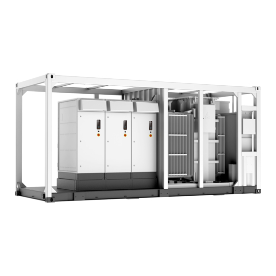
Sungrow MVS4480-US User Manual
The pad-mounted transformer
Hide thumbs
Also See for MVS4480-US
:
System manual
(71 pages)
1
2
3
4
Table Of Contents
5
6
7
8
9
10
11
12
13
14
15
16
17
18
19
20
21
22
23
24
25
26
27
28
29
30
31
32
33
34
35
36
37
38
39
40
41
42
43
44
45
46
47
48
49
50
51
52
53
54
55
56
page
of
56
Go
/
56
Contents
Table of Contents
Troubleshooting
Bookmarks
Table of Contents
All Rights Reserved
Table of Contents
1 About this Manual
Validity
Target Group
How to Use this Manual
Symbol Explanations
2 Product Description
Four Views
Exterior Dimensions
3 Electrical Connection
Connection Area
Connection Procedure
Cable Fixture
4 Logistic & Handling
Shipment
Oil Level
Hoisting
Storage
Storage Requirements
Cold Start
5 Inspection
Receiving Inspection
Internal Transformer Inspection
6 Design Consdieration
Space for Handling and Ventilation
Ambient Temperature
Altitude
Voltage Variation
Audible Sound Emissions
7 Service Preparation
Low Voltage and High Voltage Electrical Connections
Connections
Ground Connections
Pre-Commissioning Check
Recommended Torque
8 Components and Accessories
General
Cover Mounted Pressure Relief
Expulsion Fuse
Bay-O-Net Type
Remove Fuse Holder
Replace Fuse Link
Terminal Board Type
HV Bushing
Earthing Plate
Bushing
Off-Load Tap Changer
Oil Level Indicator
Schrader Valve
Transformer Pressure Gauge
Overpressure Relief Valve
Oil Filling Valve
Oil Temperature Gauge
Load Switch
Two Position Load Switch
Four Position Load Switch
Oil Draining Valve
9 Transformer Maintenance Guide
Security
Maintenance Plan
Maintenance Procedures
10 Fast Reference for Troubleshooting
11 Contact Information
Advertisement
Quick Links
1
About this Manual
2
Product Description
3
Four Views
4
Connection Area
5
Electrical Connection
6
Low Voltage and High Voltage Electrical Connections
Download this manual
User Manual
The Pad-mounted Transformer
The Pad-
mounted TransformerUser
ManualPMT-UEN-Ver12-202401
PMT-UEN-Ver12-202401
Table of
Contents
Previous
Page
Next
Page
1
2
3
4
5
Advertisement
Table of Contents
Need help?
Do you have a question about the MVS4480-US and is the answer not in the manual?
Ask a question
Questions and answers
Related Manuals for Sungrow MVS4480-US
Power Supply Sungrow MVS3200-US System Manual
Mv station (71 pages)
Media Converter Sungrow SC2400UD-MV-US User Manual
Mv power converter (151 pages)
Storage Sungrow SC2400UD-MV-US System Manual
Turnkey station (133 pages)
Inverter Sungrow SG3150UD-MV-US User Manual
Mv grid-connected pv inverter (121 pages)
Industrial Equipment Sungrow SG3425UD-MV System Manual
Mv turnkey station (121 pages)
Inverter Sungrow SG3150UD-MV-US System Manual
Mv grid-connected inverter (108 pages)
Power Supply Sungrow MVS6400-LV System Manual
Mv station (69 pages)
Power Supply Sungrow MVS6840-LV System Manual
Mv station (80 pages)
Power Supply Sungrow MVS5140-LS-US User Manual
The pad-mounted transformer (56 pages)
Power Supply Sungrow PowerTitan-ST2752UX-US Manual
Battery energy storage system (91 pages)
Power Supply Sungrow SC50HV User Manual
Power conversion system (pcs) (84 pages)
Power Supply Sungrow SC1200UD User Manual
Power conversion system (137 pages)
Power Supply Sungrow PowerTitan1.0 Maintenance Manual
(236 pages)
Power Supply Sungrow SG80KTL-20 Quick Installation Manual
(19 pages)
This manual is also suitable for:
Sg4400ud-mv-us
Sg3600ud-mv
Sg3425ud-mv
Mvs3200-us
Sg3150ud-mv-us
Sc2750ud-mv-us
...
Show all
Sc3150ud-mv-us
Sc3450ud-mv-us
Sc4000ud-mv-us
Sc5000ud-mv-us
Mvs5140-ls-us
Table of Contents
Save PDF
Print
Rename the bookmark
Delete bookmark?
Delete from my manuals?
Login
Sign In
OR
Sign in with Facebook
Sign in with Google
Upload manual
Upload from disk
Upload from URL


Need help?
Do you have a question about the MVS4480-US and is the answer not in the manual?
Questions and answers