Sign In
Upload
Download
Table of Contents
Contents
Add to my manuals
Delete from my manuals
Share
URL of this page:
HTML Link:
Bookmark this page
Add
Manual will be automatically added to "My Manuals"
Print this page
×
Bookmark added
×
Added to my manuals
Manuals
Brands
JUKI Manuals
Sewing Machine
MO-2000 Series
Service manual
JUKI MO-2000 Series Service Manual
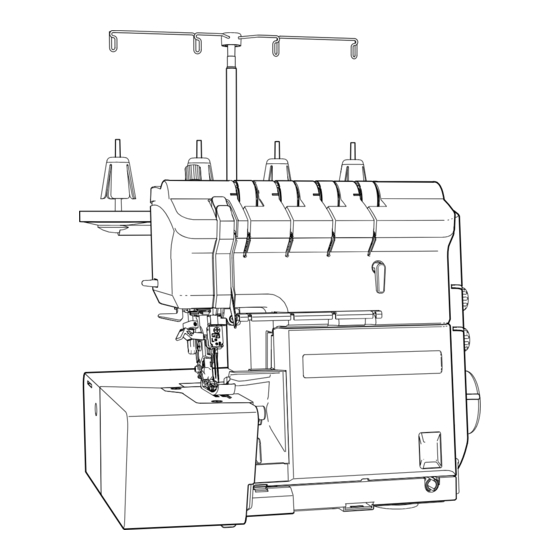
2-needle, 2/3/4-thread overlock sewing machine
Hide thumbs
1
2
Table Of Contents
3
4
5
6
7
8
9
10
11
12
13
14
15
16
17
18
19
20
21
22
23
24
25
26
27
28
29
30
31
32
33
34
35
36
37
38
39
40
41
42
43
44
45
46
47
48
49
50
51
52
53
54
55
56
57
58
59
60
61
62
63
64
65
66
67
68
69
70
71
72
73
74
75
76
77
78
79
80
81
82
83
84
85
86
87
88
page
of
88
Go
/
88
Contents
Table of Contents
Bookmarks
Table of Contents
Table of Contents
Specifications
Name of each Component
Appearance
Inside of the Cover
Standard Adjustment / Disassembly and Assembly
Removing the Top Cover
Removing the Cloth Plate Cover
Removing the Bottom Plate
Removing the Looper Cover
Removing the Side Cover
Removing the Rear Cover Removing the
Removing the Looper Cover Guide
Installation of the Throat Plate
Height of the Needle Bar
Position of the Feed Dog
Adjusting the Stroke of the Sub Feed Dog
Height of the Feed Dog
Feed Dog Timing
Position of the Balance Weights and the Cams
Projecting Amount of the Upper Looper
Radius of the Lower Looper
Adjustment of the Loop Lift
Timing between Upper and Lower Looper
Installation of the Needle Guards
Adjusting the Looper Thread Take-Up
Height and Lateral Position of the Presser Foot
Presser Foot Height by the Knee Lifting Lever
Height of the Presser Foot by the Micro Lifter (Only for the MO-2500)
Adjusting the Floating of the Disk of the Thread Tension Controller
Adjusting the Tension of the Thread Tension Controller
Position of the Needle Thread Take-Up Thread Guide
Tension of the Belt
Adjusting the Needle Bar Connection Guide of the Needle Threader
Adjusting the Needle Threader Hook
Adjusting the Looper Threader Timing
Adjusting the Pump Unit
Position of the Lower Knife
Engagement of the Upper Knife with the Lower Knife
Adjusting the Timing of the Upper Knife
Adjusting the Thread Sliding Segment
Adjusting the Safety Switch
Position of the Cloth Plate
Circuit Diagram
Maintenance
Lubrication
Grease Application
Looper Threader
Troubles and Corrective Measures
Advertisement
Quick Links
1
Table of Contents
2
Specifications
3
Standard Adjustment / Disassembly and Assembly
Download this manual
2-Needle, 2/3/4-Thread Overlock Sewing Machine
MO-2000 Series
SERVICE MANUAL
No.00
40267028
Table of
Contents
Previous
Page
Next
Page
1
2
3
4
5
Advertisement
Table of Contents
Need help?
Do you have a question about the MO-2000 Series and is the answer not in the manual?
Ask a question
Questions and answers
Subscribe to Our Youtube Channel
Related Manuals for JUKI MO-2000 Series
Sewing Machine JUKI MO-2404 Instruction Book
Mo-2400 series sewing machine (12 pages)
Sewing Machine JUKI MO-2414 Instruction Book
Mo-2400 series sewing machine (12 pages)
Sewing Machine JUKI MO-2416 Instruction Book
Mo-2400 series sewing machine (12 pages)
Sewing Machine JUKI MO-2000QVP Instruction Manual
2-needle, 2/3/4-thread overlock sewing machine (40 pages)
Sewing Machine JUKI LBH-781 Instruction Manual
(50 pages)
Sewing Machine JUKI MO-204D Instruction Manual
2-needle, 2/3/4-thread overlock sewing machine (32 pages)
Sewing Machine JUKI MO-214D Instruction Manual
2-needle, 2/3/4-thread overlock sewing machine (32 pages)
Sewing Machine JUKI MO-2800 Instruction Manual
2-needle, 2/3/4-thread overlock sewing machine (40 pages)
Sewing Machine JUKI MO-2500 Service Manual
2-needle, 2/3/4-thread overlock sewing machine (88 pages)
Sewing Machine JUKI DDL-5530N Handbook
Juki industrial sewing machines handbook (272 pages)
Sewing Machine Juki MO-734DE Instruction Manual
2-needle, 2/3/4-thread overlock sewing machine (46 pages)
Sewing Machine JUKI MO-654DE Instruction Manual
2-needle, 2/3/4-thread overlock sewing machine (40 pages)
Sewing Machine JUKI MO-644D Instruction Manual
(42 pages)
Sewing Machine JUKI MO-644 Instruction Manual
2-needle, 2/3/4-thread overlock sewing machine (42 pages)
Sewing Machine JUKI MO-6714S Instruction Manual
(92 pages)
Sewing Machine JUKI MO-644DN Instruction Manual
2-needle, 2/3/4-thread overlock sewing machine (36 pages)
This manual is also suitable for:
Mo-2500
Table of Contents
Save PDF
Print
Rename the bookmark
Delete bookmark?
Delete from my manuals?
Login
Sign In
OR
Sign in with Facebook
Sign in with Google
Upload manual
Upload from disk
Upload from URL


Need help?
Do you have a question about the MO-2000 Series and is the answer not in the manual?
Questions and answers