Table of Contents
Advertisement
Quick Links
Advertisement
Table of Contents

Subscribe to Our Youtube Channel
Related Manuals for IFM Electronic efector 500 PN73 Series


Summary of Contents for IFM Electronic efector 500 PN73 Series
- Page 1 Operating instructions Pressure sensor PN73xx...
-
Page 2: Table Of Contents
Contents 1 Preliminary note ���������������������������������������������������������������������������������������������������3 1�1 Symbols used ������������������������������������������������������������������������������������������������3 2 Safety instructions �����������������������������������������������������������������������������������������������3 3 Functions and features ����������������������������������������������������������������������������������������4 4 Function ���������������������������������������������������������������������������������������������������������������4 4�1 Processing of the measured signals ��������������������������������������������������������������4 4�2 Switching function ������������������������������������������������������������������������������������������5 4�3 Diagnostic function ����������������������������������������������������������������������������������������5 5 Installation������������������������������������������������������������������������������������������������������������6 6 Electrical connection ��������������������������������������������������������������������������������������������6 7 Operating and display elements �������������������������������������������������������������������������7 8 Menu ��������������������������������������������������������������������������������������������������������������������8 8�1 Menu structure �����������������������������������������������������������������������������������������������8... -
Page 3: Preliminary Note
1 Preliminary note 1.1 Symbols used ► Instruction > Reaction, result […] Designation of pushbuttons, buttons or indications → Cross-reference Important note: Non-compliance can result in malfunctions or interference� 2 Safety instructions • Please read this document prior to set-up of the unit� Ensure that the product is suitable for your application without any restrictions�... -
Page 4: Functions And Features
• When the damping device is removed the damping device can become unus- able� If you have any questions, please contact ifm electronic’s sales specialists� 4 Function 4.1 Processing of the measured signals • The unit displays the current system pressure�... -
Page 5: 4�2 Switching Function
4.2 Switching function OUTx changes its switching state if it is above or below the set switching limits (SPx, rPx)� The following switching functions can be selected: • Hysteresis function / normally open: [OUx] = [Hno] (→ fig. 1). • Hysteresis function / normally closed: [OUx] = [Hnc] (→ fig. 1). First the set point (SPx) is set, then the reset point (rPx) with the requested diffe- rence�... -
Page 6: Installation
5 Installation Before mounting and removing the sensor, make sure that no pressure is applied to the system� ► Insert the unit in a 7/16-20 UNF (SAE) process connection� ► Tighten firmly� 6 Electrical connection The unit must be connected by a qualified electrician� The national and international regulations for the installation of electrical equipment must be adhered to�... -
Page 7: Operating And Display Elements
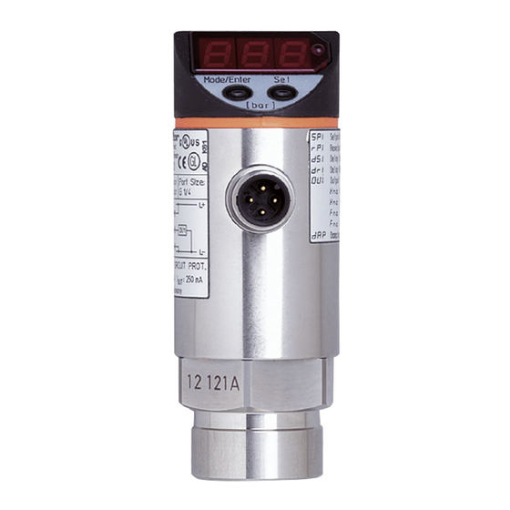
7 Operating and display elements 3 4 5 6 Mode/Enter 1 to 8: Indicator LEDs - LED 1 to LED 3 = system pressure in unit of measurement as indicated on the label� - LEDs 4, 5 and 6 not used� - LED 7, LED 8 = switching state of the corresponding output�... -
Page 8: Menu
8 Menu 8.1 Menu structure... -
Page 9: 8�2 Explanation Of The Menu
8.2 Explanation of the menu SP1/rP1 Upper / lower limit value for system pressure at which OUT1 switches� SP2/rP2 Upper / lower limit value for system pressure at which OUT2 switches� Output function for OUT1: • Switching signal for the pressure limit values: hysteresis function [H ��] or window function [F ��], either normally open [�... -
Page 10: Parameter Setting
9 Parameter setting During parameter setting the unit remains in the operating mode� It continues its monitoring function with the existing parameters until the parameter setting has been completed� 9.1 General parameter setting 3 steps must be taken for each parameter setting: Parameter selection ►... - Page 11 ► Press [Set] and keep it pressed until Mode/Enter Set the valid code no� is displayed� ► Press [Mode/Enter] briefly� On delivery by ifm electronic: no access restriction� ► Press [Set] briefly� > The first parameter of the sub-menu Mode/Enter Set is displayed (here: [Uni])�...
-
Page 12: 9�2 Configuring The Display (Optional)
9.2 Configuring the display (optional) ► Select [Uni] and set the unit of of measurement: - [bar], [MPa], [PSI]� ► Select [diS] and set update rate and orientation of the display: - [d1]: Update of the measured value every 50 ms� - [d2]: Update of the measured value every 200 ms�... -
Page 13: 9�4 User Settings (Optional)
9.4 User settings (optional) 9.4.1 Setting of a time delay for the switching signals [dS1] / [dS2] = switch-on delay for OUT1 / OUT2� [dr1] / [dr2] = switch-off delay for OUT1 / OUT2� ► Select [dS1], [dS2], [dr1] or [dr2] and set a value between 0�1 and 50 s (at 0�0 the delay time is not active)�... -
Page 14: Operation
10 Operation After power on, the unit is in the Run mode (= normal operating mode)� It carries out its measurement and evaluation functions and provides output signals accor- ding to the set parameters� Operating indications → chapter 7 Operating and display elements. 10.1 Reading of the set parameters ►... -
Page 15: Scale Drawing
11 Scale drawing 7/16-20 UNF (SAE) Dimensions are in millimeters 1: display 2: LED’s 3: programming button... -
Page 16: Technical Data
12 Technical data Operating voltage [V] ������������������������������������������������������������������������������������������18���36 DC Current consumption [mA] ��������������������������������������������������������������������������������������������� < 50 Current rating per switching output [mA] ������������������������������������������������������������������������ 250 Reverse polarity protection, overload protection ������������������������������������������������� up to 40 V Short-circuit protection; Integrated watchdog Voltage drop [V] �������������������������������������������������������������������������������������������������������������� < 2 Power-on delay time [s] ��������������������������������������������������������������������������������������������������... -
Page 17: 12�1 Setting Ranges
12.1 Setting ranges SP1 / SP2 rP1 / rP2 ΔP 5790 5760 0�4 40�0 0�2 39�8 0�2 1450 1440 1�0 100�0 0�5 99�5 0�5 0�10 10�00 0�05 9�95 0�05 0�2 25�0 0�1 24�9 0�1 0�02 2�50 0�01 2�49 0�01 -0�90 10�00 -0�95 9�95... -
Page 18: Factory Setting
13 Factory setting Factory setting User setting 25% VMR* 23% VMR* 75% VMR* 73% VMR* * = the indicated percentage of the final value of the measuring range (VMR) of the corresponding sensor in PSI is set� Further information at www�ifm�com...
Need help?
Do you have a question about the efector 500 PN73 Series and is the answer not in the manual?
Questions and answers