Table of Contents
Advertisement
Advertisement
Table of Contents

Subscribe to Our Youtube Channel
Related Manuals for IFM Electronic Efector 500 PN20 Series


Summary of Contents for IFM Electronic Efector 500 PN20 Series
- Page 1 Operating instructions Combined pressure sensor PN20xx...
-
Page 2: Table Of Contents
Contents 1 Preliminary note ���������������������������������������������������������������������������������������������������3 1�1 Symbols used ������������������������������������������������������������������������������������������������3 2 Safety instructions �����������������������������������������������������������������������������������������������3 3 Function and features ������������������������������������������������������������������������������������������4 4 Function ���������������������������������������������������������������������������������������������������������������5 4�1 Communication, parameter setting and evaluation ���������������������������������������5 4�2 Switching function ������������������������������������������������������������������������������������������6 4�3 Analogue function �����������������������������������������������������������������������������������������6 5 Installation������������������������������������������������������������������������������������������������������������8 6 Electrical connection ��������������������������������������������������������������������������������������������8 7 Operating and display elements ��������������������������������������������������������������������������9 8 Menu ������������������������������������������������������������������������������������������������������������������10 8�1 Menu structure ���������������������������������������������������������������������������������������������10... -
Page 3: Preliminary Note
11 Scale drawing ��������������������������������������������������������������������������������������������������18 12 Technical data ��������������������������������������������������������������������������������������������������19 12�1 Setting ranges �������������������������������������������������������������������������������������������21 13 Factory setting �������������������������������������������������������������������������������������������������23 1 Preliminary note 1.1 Symbols used ► Instruction > Reaction, result […] Designation of buttons, switches or indications → Cross-reference Important note Non-compliance can result in malfunctions or interference� 2 Safety instructions •... -
Page 4: Function And Features
3 Function and features The pressure sensor detects the system pressure of machines and installations� Applications Type of pressure: relative pressure Permissible Order no. Measuring range Bursting pressure overload pressure PN2020 0���400 0���5 800 8 700 1 000 14 500 PN2021 0���250 0���3 630... -
Page 5: Function
4 Function 4.1 Communication, parameter setting and evaluation • The unit shows the current system pressure on its display� • It generates 2 output signals according to the parameter setting� OUT1 • switching signal for pressure limit values� • switching signal for pressure limit values� OUT2 •... -
Page 6: 4�2 Switching Function
4.2 Switching function OUTx changes its switching state if it is above or below the set switching limits (SPx, rPx)� The following switching functions can be selected: • Hysteresis function / normally open: [OUx] = [Hno] (→ fig. 1). • Hysteresis function / normally closed: [OUx] = [Hnc] (→ fig. 1). First the set point (SPx) is set, then the reset point (rPx) at the requested distance�... - Page 7 Voltage output 0 ... 10 V Factory setting Measuring range scaled U [V] U [V] P = system pressure, MEW = final value of the measuring range In the set measuring range the output signal is between 0 and 10 V� It is also indicated: System pressure above the measuring range: output signal >...
-
Page 8: Installation
5 Installation Before mounting and removing the sensor, make sure that no pressure is applied to the system� ► Insert the unit in a G¼ process connection� ► Tighten firmly� 6 Electrical connection The unit must be connected by a qualified electrician� The national and international regulations for the installation of electrical equipment must be adhered to�... -
Page 9: Operating And Display Elements
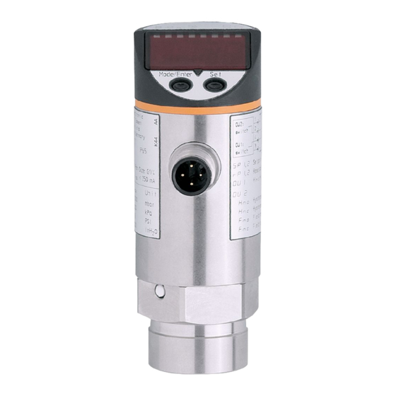
7 Operating and display elements 1 2 3 4 5 6 7 8 Mode/Enter Set 1 to 8: Indicator LEDs - LED 1 to LED 6 = system pressure in unit of measurement as indicated on the label� - LEDs 4 to 6 not used for units with 3 adjustable units of measurement� - LEDs 5 and 6 not used for units with 4 adjustable units of measurement�... -
Page 10: Menu
8 Menu 8.1 Menu structure... -
Page 11: 8�2 Explanation Of The Menu
8.2 Explanation of the menu SP1/rP1 Maximum / minimum value for system pressure, at which output 1 changes its switching status� SP2/rP2 Maximum / minimum value for system pressure, at which output 2 changes its switching status� Output function for OUT1: •... -
Page 12: Parameter Setting
9 Parameter setting During the parameter setting process the unit remains in the operating mode� It continues its monitoring function with the existing parameters until parameter set- ting has been terminated� 9.1 Parameter setting general Each parameter setting requires 3 steps: Parameter selection ►... - Page 13 ► Press [Set] and keep it pressed until Mode/Enter Set the valid code no� is displayed� ► Press [Mode/Enter] briefly� On delivery by ifm electronic: no access restriction� ► Press [Set] briefly� > The first parameter of the sub-menu Mode/Enter Set is displayed (here: [HI])�...
-
Page 14: 9�2 Setting The Output Signal
• Timeout: If no button is pressed for 15 s while the parameters are being set, the unit returns to the operating mode with unchanged values� 9.2 Setting the output signal 9.2.1 Setting the output function ► Select [OU1] and set the switching function: [Hno] = hysteresis function / normally open, [Hnc] = hysteresis function / normally closed, [Fno] = window function / normally open,... -
Page 15: 9�3 User Settings (Optional)
9.3 User settings (optional) 9.3.1 Setting the unit of measurement for the system pressure ► Select [Uni] and set the unit of measurement: [bAr], [mbAr] [MPA], [kPA] [PSI] [IH2O] (only PN2009, PN2027, PN2028, PN2069) [inHG] (only PN2009) [mmWS] (only PN2028) 9.3.2 Configuring the display ►... -
Page 16: 9�3�5 Setting The Output Polarity
9.3.5 Setting the output polarity ► Select [P-n], set [PnP] or [nPn]� 9.3.6 Setting the damping for the switching outputs ► Select [dAP], set value between 0�01 ��� 4�00 s; (at 0�00 [dAP] time is not active)� dAP-value = response time between pressure change and change of the switching status in seconds (s)�... -
Page 17: Operation
10 Operation After power on of the supply voltage the unit is in the Run mode (= normal opera- tion)� It carries out its measurement and evaluation functions and generates output signals according to the set parameters� Operating indicators → chapter 7 Operating and display elements. 10.1 Read the set parameter values ►... -
Page 18: Scale Drawing
11 Scale drawing 47,8 21,5 Dimensions are in millimeters = dimensions for PN2060 1: display; 2: LED’s; 3: programming button... -
Page 19: Technical Data
12 Technical data Operating voltage [V] ����������������������������������������������������������������������������������������� 18���32 DC Current consumption [mA] ��������������������������������������������������������������������������������������������� < 35 Current rating [mA] ��������������������������������������������������������������������������������������������������� 2 x 250 Protection: short circuit, reverse polarity, overload Voltage drop [V] �������������������������������������������������������������������������������������������������������������� < 2 Power-on delay [s] ���������������������������������������������������������������������������������������������������������� 0�3 Min� response time switching outputs [ms] ��������������������������������������������������������������������� 1�5 Switching frequency [Hz] ���������������������������������������������������������������������������������������max�... - Page 20 Materials (wetted parts) ����������������������������stainless steel (303S22); ceramics; FPM (Viton) Housing material ���������stainless steel (304S15); stainless steel (316S12); PBTP (Pocan); PEI; FPM (Viton) in addition PTFE for PN2009, PN2023, PN2024, PN2026, PN2027, PN2028, PN2069 Protection PN2020, PN2021, PN2022, PN2060 ���������������������������������������������������������� IP 67 Protection PN2009, PN2023, PN2024, PN2026, PN2027, PN2028, PN2069 �������������...
-
Page 21: 12�1 Setting Ranges
12.1 Setting ranges SP1 / SP2 rP1 / rP2 ΔP mbar -988 1000 -996 -996 -496 1000 -14�3 14�5 -14�4 14�4 -14�4 7�3 -7�2 14�5 0�1 -98�8 -99�6 99�2 -99�6 50�0 -49�6 0�4 inH2O -396 -399 -400 -199 inHg -29�1 29�5 -29�4 29�3... - Page 22 SP1 / SP2 rP1 / rP2 ΔP mbar 1000 1000 -0�68 14�50 -0�74 14�44 -0�74 10�88 3�64 14�50 0�02 -4�6 100�0 -5�0 99�6 -5�0 75�0 25�0 100�0 0�2 inH2O -18�5 401�5 -20�0 400�0 -20�0 301�0 100�5 401�5 0�5 mbar -10�5 250�0 -11�5 249�0...
-
Page 23: Factory Setting
13 Factory setting Factory setting User setting 25 % VMR* 23 % VMR* 75 % VMR* 73 % VMR* PN2009: -996 mbar PN2069: -500 mbar 100 % VMR* 0.06 0.10 bAr / mbAr * = the indicated percentage of the final value of the measuring range of the correspond- ing sensor in bar / mbar is set (for PN20x9 the percentage of the span)�...
Need help?
Do you have a question about the Efector 500 PN20 Series and is the answer not in the manual?
Questions and answers