Table of Contents
Advertisement
Quick Links
Advertisement
Table of Contents

Related Manuals for IFM Electronic LR2050


Summary of Contents for IFM Electronic LR2050
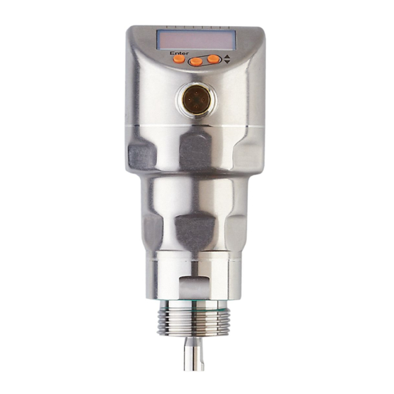
- Page 1 Operating instructions Electronic level sensor LR2050...
-
Page 2: Table Of Contents
Contents 1 Preliminary note ���������������������������������������������������������������������������������������������������5 1�1 Symbols used ������������������������������������������������������������������������������������������������5 2 Safety instructions �����������������������������������������������������������������������������������������������5 3 Items supplied������������������������������������������������������������������������������������������������������6 4 Getting started �����������������������������������������������������������������������������������������������������6 5 Functions and features ����������������������������������������������������������������������������������������7 5�1 Application area ��������������������������������������������������������������������������������������������7 5�2 Restriction of the application area �����������������������������������������������������������������7 6 Function ���������������������������������������������������������������������������������������������������������������8 6�1 Measuring principle ���������������������������������������������������������������������������������������8 6�2 Outputs ����������������������������������������������������������������������������������������������������������9 6�3 Other features of the unit �������������������������������������������������������������������������������9 6�3�1 Display functions ����������������������������������������������������������������������������������9... - Page 3 7�4�2 Installation of the coaxial pipe ������������������������������������������������������������21 7�5 Rod length ��������������������������������������������������������������������������������������������������22 7�5�1 Shortening of the rod ��������������������������������������������������������������������������22 7�5�2 Determine rod length L for single probes��������������������������������������������22 7�5�3 Shortening of the coaxial pipe ������������������������������������������������������������23 7�5�4 Determine rod length L for coaxial probes �����������������������������������������23 7�6 Installation of the unit with single probe �������������������������������������������������������24 7�6�1 Installation to G¾...
- Page 4 11�4�5 Set the switch-off delay for switching outputs �����������������������������������40 11�4�6 Setting of the output function for OUT2 ��������������������������������������������40 11�4�7 Scale analogue signal �����������������������������������������������������������������������40 11�4�8 Set output logic for the switching outputs �����������������������������������������41 11�4�9 Response of the outputs in case of a fault ����������������������������������������41 11�4�10 Set damping for the measured signal ���������������������������������������������41 11�4�11 Set delay time in case of a fault ������������������������������������������������������41 11�5 Reset all parameters to factory setting ������������������������������������������������������41...
-
Page 5: Preliminary Note
1 Preliminary note 1.1 Symbols used ► Instructions > Reaction, result […] Designation of keys, buttons or indications → Cross-reference Important note Non-compliance may result in malfunction or interference� Information Supplementary note� 2 Safety instructions • The device described is a subcomponent for integration into a system� - The manufacturer of the system is responsible for the safety of the system�... -
Page 6: Items Supplied
• mounting material (if necessary, a launching plate) (→ 12.1) ► In the event of incomplete or damaged items supplied please contact ifm electronic� ► Only use accessories from ifm electronic� Accessories: www�ifm�com The optimum function is not ensured when using components from other manufacturers�... -
Page 7: Functions And Features
5 Functions and features The unit continuously detects the level in tanks� 5.1 Application area • Water, water-based media • Oils, oil-based media (only for operation with coaxial probe) • Compatible with G ¾ process connections Application examples: - Detection of cleaning liquid in a parts cleaning system - Monitoring of hydraulic oil in a hydraulic power unit (only for operation with coaxial probe) - Detection of cooling water in an industrial cooling system... -
Page 8: Function
• The unit is not suitable for applications where the rod is subjected to permanent and high mechanical stress (e�g� fast moving viscous media or fast flowing media)� • In case of operation with single probe: use preferably in metal tanks� When used in plastic tanks, deterioration caused by electromagnetic interference may occur (noise immunity to EN61000-6-2)�Corrective measures: (→... -
Page 9: 6�2 Outputs
The figures show the operation with single probe� In case of operation with a coaxial probe, the guided wave runs only along the inside of the coaxial pipe� 6.2 Outputs The unit generates output signals according to the parameter setting� 2 outputs are available�... -
Page 10: 6�3�2 Analogue Function
6.3.2 Analogue function The unit provides an analogue signal proportional to the level� The analogue output (OUT2) can be set ((→ 11.4.6) and the following illustrationss)� • [ou2] defines the output function of the analogue output: - current output rising ([ou2] = [I]) or - current output falling ([ou2] = [InEG]) (→... - Page 11 Curve of the analogue signal (measuring range scaled): I [mA] ASP2 AEP2 ① L: Level [ou2] = I (factory setting) ② A: Active zone = rod length L - (I1 + I2) [ou2] = [InEG] I1: Inactive zone 1 ASP2: Analogue start point I2: Inactive zone 2 (→...
-
Page 12: 6�3�3 Switching Functions
6.3.3 Switching functions Via switching output OUT1 (factory setting) or additionally via OUT2 (can be set) the unit signals that a set limit level has been reached or that the level is below the limit� The following switching functions can be selected: •... -
Page 13: 6�3�4 Damping Function
6.3.4 Damping function With unsteady level (e�g� turbulence, wave movements���) display and output response may be damped� During damping the determined level values are "smoothed" by means of a mean filter; the result is a steady curve� Damping can be set by means of the parameter [dAP] (→ 11.4.10)� [dAP] indicates in seconds after what time 63 % of the final value are reached in the event of a sudden jump�... -
Page 14: 6�3�7 Io-Link
6.3.7 IO-Link This unit has an IO-Link communication interface which requires an IO-Link capable module (IO-Link master) for operation� The IO-Link interface enables direct access to the process and diagnostic data and provides the possibility to set the parameters of the unit during operation� In addition, communication is possible via a point-to-point connection with a USB adapter cable�... -
Page 15: 7�2�1 Minimum Distances And Minimum Connection Piece Diameter
7.2.1 Minimum distances and minimum connection piece diameter Fig. 7-1 Fig. 7-2 Without adjustment Installation distances with adjustment (→ Installation distances without adjustment 7�2�7) 10 mm A1: 10 mm 20 mm A2: 50 mm 20 mm to tank structures (B) A3: 50 mm to tank structures (B) 50 mm to other sensors type LR 50 mm to other sensors type LR... -
Page 16: 7�2�3 Applications With Viscous And Fast Flowing Media
7.2.3 Applications with viscous and fast flowing media For applications with viscous or flowing media and / or agitators in which the rod is exposed to lateral load: Fig.. 7-3 ► Rod must not be in contact with tank wall / structures� ►... -
Page 17: 7�2�5 In Case Of Heavy Soiling
7.2.5 In case of heavy soiling If the medium is highly polluted, there is the risk that a bridge forms between the rod and the tank wall or structures in the tank� ► Increase minimum distances depending on the pollution intensity� 7.2.6 Heavy foam build-up and turbulence Heavy foam build-up and turbulence may lead to incorrect measurements�... -
Page 18: 7�2�7 Notes On Tank Adjustment
With increased foam formation the setting [MEdI] = [MId] is recommended (→ 11.2.3)� 7.2.7 Notes on tank adjustment Tank adjustment reduces the effect of interference and ensures a higher excess gain in difficult application conditions� Carry out the tank adjustment only when the unit is installed� For the tank adjustment it is necessary to enter an "adjustment distance"... -
Page 19: 7�3 Unit With Coaxial Probe
No tank adjustment is necessary if all installation distances (→ 7.2) are adhered to� The unit is then ready for operation without tank adjustment� ► In case of doubt carry out a tank adjustment (recommended!)� Carry out a tank adjustment with empty tank, if possible, to cover any possible interfering sources�... -
Page 20: 7�4 Installation Of The Rod
7.4 Installation of the rod The probe is not supplied. It has to be ordered separately (→ 3 Items supplied). 7.4.1 Installation of the rod Fixing of the rod: ► Screw the rod to the unit and tighten it� Recommended tightening torque: 4 Nm� For ease of installation and removal the rod connection can be rotated without restriction�... -
Page 21: 7�4�2 Installation Of The Coaxial Pipe
7.4.2 Installation of the coaxial pipe This subchapter is only relevant if the unit is to be operated with a coaxial probe� The coaxial pipe and the rod must be of the same end length� The coaxial pipe can be shortened (→ 7.5.2)� ►... -
Page 22: 7�5 Rod Length
7.5 Rod length 7.5.1 Shortening of the rod The rod can be shortened to adapt to different tank heights� Ensure that the rod length is not below the minimum permissible rod length of 150 mm (L )� The unit does not support rod lengths below 150 mm� For probe lengths <... -
Page 23: 7�5�3 Shortening Of The Coaxial Pipe
7.5.3 Shortening of the coaxial pipe The coaxial pipe and the rod must be of the same end length: ► Remove fastening bracket and Fig. 7-9 centring piece (A, B)� ► Shorten the coaxial pipe to the requested length: L = L + 9 mm ►... -
Page 24: 7�6 Installation Of The Unit With Single Probe
7.6 Installation of the unit with single probe Before installing and removing the unit: Make sure that no pressure is applied to the system and that there is no medium in the tank that could leak� Also always take into account the potential dangers related to extreme machine and medium temperatures�... -
Page 25: 7�6�2 Installation In The Tank Lid Using A Flange Plate
7.6.2 Installation in the tank lid using a flange plate Fig. 7-11 Fig.. 7-12 ► Arrange for a bore hole in the tank lid� It must have a minimum diameter d to enable sufficient transfer of the measured signal to the probe (fig� 7-11)� The diameter (d) depends on the wall thickness of the tank lid: Wall thickness [mm] 1���5... -
Page 26: 7�6�3 Installation In Open Tanks
7.6.3 Installation in open tanks ► For installation in open tanks, use a metal fixture to install the unit� It serves as a launching plate R; minimum size: 150 x 150 mm for a square fixture, 150 mm diameter for a circular fixture (→ 12.1)� ►... -
Page 27: 7�6�4 Installation In Plastic Tanks
7.6.4 Installation in plastic tanks Min� 150 mm Launching plate To enable sufficient transfer of the measured signal, note in case of installation in plastic tanks or metal tanks with plastic lid: ► A drill hole with a minimum diameter of 150 mm must be applied to the plastic lid�... -
Page 28: 7�7 Installation Of The Unit With Coaxial Probe
7.7 Installation of the unit with coaxial probe ► Seal the process connection: - For coaxial pipes with G¾ process connection: Slide the supplied seal onto the thread of the coaxial pipe� - For coaxial pipes with ¾" NPT process connection: Apply a suitable sealing material (e�g�... -
Page 29: Electrical Connection
8 Electrical connection The unit must be connected by a qualified electrician� The national and international regulations for the installation of electrical equipment must be adhered to� Voltage supply according to SELV, PELV� For marine applications (if approval available for the device), additional surge protection is required�... -
Page 30: Operating And Display Elements
9 Operating and display elements 1 to 8: Indicator LEDs LEDs Selected unit of measurement� 1 - 3 LEDs Not used� 4 - 6 LED 7 Only active if the switching output [ou2] = [I] or [InEG] is selected; then: Switching status OUT2 (on when output 2 is switched)�... -
Page 31: Menu
10 Menu 10.1 Menu structure inch Menu items highlighted in grey, e�g� [ SP2 ], are only active when assigned parameters have been selected (→ 10.2.1)� Main menu (→ 10.2.1) EF Level (→ 10.2.2) - Page 32 Menu items highlighted in grey, e�g� [ dS2 ], are only active when assigned parameters have been selected (→ 10.2.3)� III : CFG level (→ 10.2.3) ENV level (→ 10.2.4) SIM level (→ 10.2.5)
-
Page 33: 10�2 Explanation Of The Menu
10.2 Explanation of the menu 10.2.1 Main menu [I] tREF Carry out tank adjustment� Menu item only visible if [LEnG] ≥ 260 mm and [Prob] = [rod] SP1 / rP1 Set point 1 / reset point at which OUT1 switches� Menu item only visible if hysteresis function is selected ([ou1] = [H��]) FH1 / FL1 Upper / lower limit for the acceptable range within which OUT1 switches�... -
Page 34: 10�2�3 Cfg Level (Configuration) [Iii]
10.2.3 CFG level (configuration) [III] Output configuration for OUT1: • Switching signal for level limit value� Hysteresis or window function, normally closed or normally open Output configuration for OUT2: • Analogue signal for current level, 4…20 mA or 20…4 mA •... -
Page 35: Parameter Setting
11 Parameter setting During parameter setting the device remains in the operating mode� It continues its monitoring functions with the existing parameters until the parameter setting has been completed� 11.1 Parameter setting in general Select parameter ► Press [Enter] to get to the menu� ►... - Page 36 • Change from menu level 1 to menu level 2: ► Press [Enter] to get to the menu� ► Press [▲] or [▼] until [EF] is displayed� ► Press [Enter]� > The first parameter of the submenu is displayed (here: [rES])� •...
-
Page 37: 11�2 Basic Settings (Set
11.2 Basic settings (set-up) On delivery of the unit, you must first enter the basic settings� The complete user menu then opens� 11.2.1 Entering the type of probe used ► Apply operating voltage� > The initial display is shown� ► Select [Prob] and set: ►... -
Page 38: 11�2�3 Setting To The Medium
11.2.3 Setting to the medium ► Select [MEdI] and set: [HIGH] = For water and water-based media� Operating mode is optimised for suppression of deposits on the rod� [MId] = For water-based media and media with a medium dielectric constant value, e�g� water-in-oil emulsions� Operating mode optimised for the detection of media with increased foam build-up�... -
Page 39: 11�3 Configure Display (Optional)
11.3 Configure display (optional) ► Select [uni] and set the unit of measurement: [mm], [inch]� Factory setting: mm� ► Select [SELd] and set type of indication: [L] = The level is indicated in mm or inch� [%] = The level is indicated in percent of the measuring range / scaled measuring range�... -
Page 40: 11�4�3 Set The Switching Limits (Window Function)
11.4.3 Set the switching limits (window function) ► Make sure that for [oux] the function [Fno] or [Fnc] is set� ► Select [FHx] and set the upper limit of the acceptable range� ► Select [FLx] and set the lower limit of the acceptable range� [FLx] is always lower than [FHx]�... -
Page 41: 11�4�8 Set Output Logic For The Switching Outputs
11.4.8 Set output logic for the switching outputs ► Select [P-n] and set [PnP] or [nPn]� 11.4.9 Response of the outputs in case of a fault ► Select [FOU1] / [FOU2] and set the value: [On] = Output switches ON in case of a fault Analogue output switches to a value >... -
Page 42: 11�6 Changing Basic Settings
11.6 Changing basic settings Required after changes to the rod or application� 11.6.1 Change the type of probe used Menu item only visible if [MEdI] = [HIGH] or [MId]� ► Select [Prob]� ► Press [Enter]� ► Press [▲] or [▼] for min. 1 s and set the value: [rod] = Single probe [COAX] =... -
Page 43: 11�7 Simulation
11.7 Simulation 11.7.1 Set simulation value ► Select [S�LvL] ► Set the process value to be simulated: [Numerical Level in mm / inch (depending on the basic setting) value] = [FULL] = Full state [SEnS] = Weak measured signal [Err] = Electronic fault found [EPTY] = Empty state... -
Page 44: Operation
12 Operation 12.1 Operation with single probe The single probe is made up of one individual rod� Operation with a single rod is suited for the detection of aqueous media, in particular of heavily soiled aqueous media� For correct function with single probe, the unit needs a sufficiently large metal launching surface / launching plate�... -
Page 45: 12�4 Operation Indication
12.4 Operation indication ---- continuous Initialisation phase after power on On delivery the unit is not operational� Basic settings required (→ 11.2)� [----] Level below the active zone Numerical value + Current level in mm LED 1 Numerical value + Current level in inches LED 2 Numerical value +... -
Page 46: 12�6 Change The Display Unit In The Operating Mode
12.6 Change the display unit in the operating mode (switching between length indication (mm / inch) and percentage)� ► Briefly press [▲] or [▼] in the operating mode. > The selected unit is displayed for 30 s, the corresponding LED is on� With each push of the button the display type is changed�... -
Page 47: 12�8 Output Response In Different Operating States
12.8 Output response in different operating states OUT1 OUT2* Initialisation According to the level and According to the level 4���20 Normal operation [ou1] setting OFF for [FOU1] = [OFF] < 3�6 mA at [FOU2] = [OFF] Fault ON for [FOU1] = [On] >... -
Page 48: Maintenance / Transport
The setting ranges for analogue start point [ASP2] and analogue end point [AEP2] depend on the rod length (L)� In general the following applies: inches [ASP2] [AEP2] L - 30 L - 1�2 Step increment 0�05 • Minimum distance between [ASP2] and [AEP2] = 20 % of the active zone� 14 Maintenance / Transport ►... -
Page 49: Factory Setting
15 Factory setting Factory setting User setting tREF nonE 50% VMR* 5 mm below SP1 ASP2 0% VMR* AEP2 100% VMR* FOU1 FOU2 SELd Prob nonE LEnG nonE MEdl nonE S.LVL 50 % LEnG S.Tim S.On * VMR = final value of the measuring range = LEnG value minus 30 (in millimetres)� When the LEnG value is entered, the unit calculates the basic setting�... -
Page 50: Notes On Parameter Setting Via Io-Link
16 Notes on parameter setting via IO-Link On delivery the unit is not operational� During set-up, valid basic settings have to be sent to the device once even if the default settings correspond to the connected device� Make sure that the basic settings are entered correctly according to the attached rod and the medium to be detected�... -
Page 51: 16�2 Unit Locking / Data Storage
Only if data storage is required in an IO-Link application: The tank adjustment is not saved via IO-Link� After a unit has failed it must be carried out again� Only when the tank adjustment has been carried out successfully does the unit revert to the cyclical process data transmission� After a factory reset (button "Restore Factory Settings"), the device reboots and the factory settings are restored�...
Need help?
Do you have a question about the LR2050 and is the answer not in the manual?
Questions and answers