Table of Contents
Advertisement
Quick Links
Advertisement
Table of Contents

Subscribe to Our Youtube Channel
Related Manuals for IFM Electronic DA102S


Summary of Contents for IFM Electronic DA102S
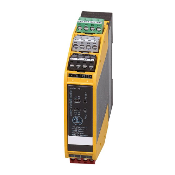
- Page 1 Original Installation Instructions Safety Standstill Monitor DA102S...
-
Page 2: Table Of Contents
Contents 1 Preliminary note ....................4 1.1 Symbols used ....................4 2 Safety instructions ....................5 3 Items supplied......................6 4 Functions and features ..................6 4.1 Requirements for the hardware configuration ..........7 4.1.1 Product-independent requirements ............7 4.1.2 Product-dependent requirements ............7 5 Function .......................8 5.1 Block diagram ....................8 5.2 Operating principle ..................8 5.3 Switching function ..................9 5.4 Switch point setting ..................9... - Page 3 7.6 Switching outputs 14-23 and 24-24 .............17 7.7 Y7 transistor output ..................17 8 Set-up ........................18 9 Display elements ....................18 9.1 LED indications and switching characteristics ..........19 9.1.1 General ....................19 9.1.2 External errors ..................19 9.1.3 Internal faults ..................20 10 Maintenance, repair and disposal ..............20 11 Technical data ....................21 12 Tests / approvals ....................23 13 Terms and abbreviations ..................24...
-
Page 4: Preliminary Note
1 Preliminary note The instructions are part of the unit. They are intended for authorised persons according to the EMC and Low Voltage Directives and safety regulations. The instructions contain information about the correct handling of the product. Read the instructions before use to familiarise yourself with operating conditions, installation and operation. -
Page 5: Safety Instructions
2 Safety instructions • Follow the operating instructions. • Improper use may result in malfunctions of the unit. This can lead to personal injury and/or damage to property during operation of the machine. For this reason note all remarks on installation and handling given in this document. Also adhere to the safety instructions for the operation of the whole installation. -
Page 6: Items Supplied
3 Items supplied • 1 safe standstill monitor DA102S including 5 Combicon connectors with screw terminals • 1 original operating instructions "Safe standstill monitor" reference no. 80001217. If one of the above-mentioned components is missing or damaged, please contact one of the ifm branch offices. -
Page 7: Requirements For The Hardware Configuration
The following points have to be ensured in the application by taking administrative measures: • The devices of type "safe standstill monitor", DA102S, in operation must be subjected to a self-test (switching on) within a period of maximum 6 months (intermittent operation). -
Page 8: Function
5 Function 5.1 Block diagram 24 V DC S34 S43 inputs switchpoint controller 1 power controller 2 fault 1: Supply voltage 4: Feedback contact 2: Inputs 5: "Standstill" switching outputs 3: Switch point setting (bridging) 6: "Fault" transistor output 5.2 Operating principle The device is a 2-channel pulse evaluation system for the safe detection of underspeed or standstill. -
Page 9: Switching Function
5.3 Switching function In accordance with a "safe standstill message", the output relays are energised when the switch point is not reached or with standstill. The output relays K1/K2 switch (are energised) when the set switch point is 5% below the set level. They switch back (are de-energised) when the set switch point is exceeded by 5%. -
Page 10: Y7 Transistor Output
5.6 Y7 transistor output The Y7 transistor output provides a non-safety related signal for communication to a PLC. Status Y7 transistor output Normal operation (no error) HIGH (ON) Error LOW (OFF) The output data is compatible with the input data of the current-sinking inputs of type 1, 2, 3 to EN 61131-2. -
Page 11: Error Message
The device monitors continuously if this condition is met. If this regulation is violated, there is an error and the device goes into the safe state. (→ 6.3 Arrangement of the damping cams) 5.9 Error message If the device detects an error, the switching outputs are kept in the safe state. The "Fault"... -
Page 12: Installation
6 Installation 6.1 Installation of the device ► Mount the device on a DIN rail in a housing protected against dust and humidity (min. IP54 - degree of soiling 2). 6.2 Installation of the pulse pick-ups (sensors) ► Mount the pulse pick-ups mechanically separated from each other. (Not together on a mounting bracket.) ►... -
Page 13: Example Cam Disc
6.3.2 Example cam disc Mechanical requirements... -
Page 14: Electrical Connection
7 Electrical connection ► Use 60/75°C copper conductors only. Do not use unconnected terminals as support point terminal. 7.1 Connections (overview) S34 S43 Y5 Y6 Combicon connector Connector Terminal Connection L-, L+ Supply voltage (→ 7.2) Switch point setting (bridging) (→ 7.3) Y4, Y5 Feedback contact (→ 7.5) -
Page 15: Supply Voltage
7.2 Supply voltage ► Connect the supply voltage of the device to terminals L+ and L-. For safety reasons the unit can only be restarted by separation from the voltage supply in case of a fault. It is thus recommended to install a RESET button in series with the L+ circuit. 24 V DC 24 V DC RESET... -
Page 16: Pulse Pick-Ups (Sensors)
7.4 Pulse pick-ups (sensors) ► Use pnp-switching sensors with the "normally open” function. ► Connect the supply voltage of the sensors to the terminals S33 and S44. ► Connect the mass of the sensors to the terminals L- and Y4. E1 E2 Y5 Y6 S34 S43... -
Page 17: Switching Outputs 14-23 And 24-24
7.6 Switching outputs 14-23 and 24-24 ► Connect to load to be controlled to the outputs C1 (13-14) and/or C2 (23-24). ► Observe the maximum and minimum load conditions (→ 11 Technical data). 3,6 A 3,6 A Switching outputs 7.7 Y7 transistor output ► Connect transistor output Y7 to the signal input of the PLC. ►... -
Page 18: Set-Up
8 Set-up The device is ready for operation after application of the supply voltage and the self-diagnosis. ► After installation and electrical connection, check whether the device operates safely. 9 Display elements Power Fault Display elements Colour Meaning (normal operation) Yellow Input signal channel 1 Output relay channel 1... -
Page 19: Led Indications And Switching Characteristics
9.1 LED indications and switching characteristics 9.1.1 General Status Power Fault K1, K2 E1, E2 Outputs Transistor 13-14, 23-24 Standstill HIGH No standstill HIGH Feedback contact HIGH open Overvoltage/ HIGH undervoltage Symbols used (→ 1.1) *) current status 9.1.2 External errors Status Power Fault K1, K2 E1, E2... -
Page 20: Internal Faults
9.1.3 Internal faults Status Power Fault K1, K2 E1, E2 Outputs Transistor 13-14, 23-24 Device-internal error A flash code is output via the "Power" LED. This flash code enables the manufacturer to analyse the device-internal error. ► If the error message is not reset in spite of the interruption of the supply voltage, exchange the device (→ 4.1.2 Product-dependent requirements). -
Page 21: Technical Data
11 Technical data... -
Page 23: Tests / Approvals
12 Tests / approvals The device was tested and certified by TÜV-Nord. The device was developed and tested in accordance with the following directives and standards: • 2006/42/EC Machinery Directive • 2004/108/EC EMC Directive • 73/23/EEC or 93/68 Low voltage directive • ISO 13849-1: 2008 Safety of machines - safety-related parts of control systems • IEC 61508: 2011 Functional safety of electrical/electronic/programmable electronic safety-related systems... -
Page 24: Terms And Abbreviations
13 Terms and abbreviations Cat. Classification of the safety-related parts of a controller as regards their resistance to failures. Common Cause Failure Diagnostic Coverage MTTF Mean Time to Failure MTTF Mean Time To Dangerous Failure Probability of (dangerous) Failure per Hour (PFH Performance Level PL to ISO 13849-1...
Need help?
Do you have a question about the DA102S and is the answer not in the manual?
Questions and answers