IFM Electronic efector150 KN5121 Operating Instructions Manual
Capacitive level sensor
Hide thumbs
Also See for efector150 KN5121:
- Operating instructions manual (23 pages) ,
- Operating instructions (3 pages) ,
- Operating instructions (3 pages)
Table of Contents
Advertisement
Quick Links
Advertisement
Table of Contents

Subscribe to Our Youtube Channel
Related Manuals for IFM Electronic efector150 KN5121


Summary of Contents for IFM Electronic efector150 KN5121
- Page 1 Operating instructions Capacitive level sensor KN5121...
-
Page 2: Table Of Contents
Contents 1 Preliminary note ���������������������������������������������������������������������������������������������������3 2 Safety instructions �����������������������������������������������������������������������������������������������3 3 Functions and features ����������������������������������������������������������������������������������������3 4 Mounting ��������������������������������������������������������������������������������������������������������������4 5 Electrical connection ��������������������������������������������������������������������������������������������5 5�1 Setting the output function as normally closed or normally open ������������������5 5�2 Function check output / programming input ��������������������������������������������������6 5�2�1 Signals on the function check output ����������������������������������������������������6 5�2�2 Programming input �������������������������������������������������������������������������������6 6 Operation �������������������������������������������������������������������������������������������������������������6... -
Page 3: Preliminary Note
1 Preliminary note ► Instructions > Reaction, result Important note Non-compliance can result in malfunction or interference� Information Supplementary note� 2 Safety instructions • Please read the operating instructions prior to set-up of the device� Ensure that the product is suitable for your application without any restrictions� • The unit conforms to the relevant regulations and EC directives�... -
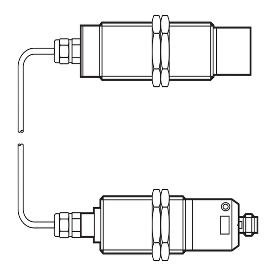
Page 4: Mounting
1: sensor 2: sensing face 3: threaded sleeve 4: programming button 5: LEDs red, yellow, green 6: evaluation electronics 4 Mounting ► Disconnect the system from power before mounting� ► Mount the unit as shown: 1: The connection cable must not be damaged� Minimum bending radius = 80 mm... -
Page 5: Electrical Connection
5 Electrical connection The unit must be connected by a qualified electrician� The national and international regulations for the installation of electrical equipment must be adhered to� ► Disconnect power� ► Connect the unit� p-switching (type FPKG) n-switching (type FNKG) 5.1 Setting the output function as normally closed or normally open The switching output of the unit can be operated as normally closed or normally... -
Page 6: 5�2 Function Check Output / Programming Input
5.2 Function check output / programming input You can select between function check output and programming input via the bidirectional wire (FC-OUT/CAL, pin 2)� • When used as function check output, output signals of the unit can be evaluated� • When used as programming input, operations can be performed� 5.2.1 Signals on the function check output Status Signal... -
Page 7: 6�1 Programming
6.1 Programming Overview of the modes and their basic functions • Operating mode Normal operating mode, all sensor functions are active� • Adjustment mode Setting of the switching threshold by empty and full adjustment� • Locking mode Locking and unlocking of the unit possible to avoid tampering� 6.1.1 Empty adjustment. -
Page 8: 6�1�2 Full Adjustment
The sensor is operational just with empty adjustment� However, it is recommended to carry out a "full adjustment" with the active zone being completely covered after empty adjustment� On the basis of the values for the empty state / full state the internal microprocessor determines the optimum position of the switching thresholds between the two states�... -
Page 9: 6�1�4 Unlocking
Factory setting: not locked� ► Press the programming button for min� 10 s� > The green LED first flashes slowly (about 1 Hz), after 5 s more quickly (about 2 Hz), after 10 s it goes out� > The unit is locked� ►... -
Page 10: Operation
• Empty adjustment outside the operating range (e�g� empty adjustment in case of direct contact with an electrically grounded medium, e�g� if the active zone is immersed in water)� ► Repeat the adjustment for error correction� Further errors • Electronic fault or sensing zone of the unit damaged� •... -
Page 11: Maintenance, Repair And Disposal
The red LED and the function check output are briefly active during the change between "medium not present" and "medium present"� This can occur in particular if the level changes very slowly and is no error message meaning a fault in the unit� 8 Maintenance, repair and disposal The operation of the unit is maintenance-free�...
Need help?
Do you have a question about the efector150 KN5121 and is the answer not in the manual?
Questions and answers