Table of Contents
Advertisement
Quick Links
Advertisement
Table of Contents

Subscribe to Our Youtube Channel
Related Manuals for IFM Electronic OPU70 Series


Summary of Contents for IFM Electronic OPU70 Series
- Page 1 Operating instructions Laser fork sensor OPU70x...
- Page 2 Contents 1 Preliminary note ���������������������������������������������������������������������������������������������������3 1�1 Symbols used ������������������������������������������������������������������������������������������������3 2 Safety instructions �����������������������������������������������������������������������������������������������3 3 Functions and features ����������������������������������������������������������������������������������������3 4 Installation������������������������������������������������������������������������������������������������������������4 5 Operating and display elements ��������������������������������������������������������������������������4 6 Electrical connection ��������������������������������������������������������������������������������������������5 7 Settings ����������������������������������������������������������������������������������������������������������������6 7�1 IO-Link �����������������������������������������������������������������������������������������������������������6 7�2 Operating elements ���������������������������������������������������������������������������������������6 7�2�1 Setting of the output function ����������������������������������������������������������������6 7�2�2 Sensitivity setting ����������������������������������������������������������������������������������7 8 Operation �������������������������������������������������������������������������������������������������������������8...
- Page 3 1 Preliminary note 1.1 Symbols used ► Instruction > Reaction, result → Cross-reference Important note Non-compliance can result in malfunctions or interference� 2 Safety instructions • Please read this document prior to set-up of the unit� Ensure that the product is suitable for your application without any restrictions�...
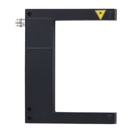
- Page 4 4 Installation T: transmitter; R: receiver ► Secure the optical fork sensor (OPU���) to a bracket� 5 Operating and display elements 1: LED yellow 2: output function switch 3: sensitivity potentiometer...
- Page 5 6 Electrical connection The unit must be connected by a qualified electrician� ► The national and international regulations for the installation of electrical equipment must be adhered to� ► Ensure voltage supply to EN 50178, SELV, PELV� The following indications apply if there is a UL listing mark on the product: ►...
- Page 6 7 Settings The unit and the parameters are set via the operating elements (→ 7.2)� For selected units, setting can be done via IO-Link (→ 7.1)� 7.1 IO-Link This unit has an IO-Link communication interface which enables direct access to process and diagnostic data�...
- Page 7 7.2.2 Sensitivity setting The sensor is to switch when the object is detected ► Set the setting potentiometer to the lowest sensitivity� ► Position the object to be detected in the detection zone� ► Increase the sensitivity until the yellow LED lights�...
- Page 8 ► Reduce the sensitivity until the yellow LED goes out� ► Remove the object from the detection zone� > The yellow LED is lit again� The setting operation is completed� 8 Operation ► Check whether the unit operates correctly� > The yellow LED is lit when the output is switched� 9 Maintenance, repair, disposal ►...
Need help?
Do you have a question about the OPU70 Series and is the answer not in the manual?
Questions and answers