
Subscribe to Our Youtube Channel
Related Manuals for IFM Electronic efector300 SA1003


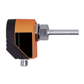
Summary of Contents for IFM Electronic efector300 SA1003
- Page 1 Bedienungsanleitung Operating instructions Notice utilisateurs Strömungssensor analog Flow sensor analog Sonde de débit analogique SA1003...
-
Page 2: Table Of Contents
Inhalt 1. Bestimmungsgemäße Verwendung ... . Seite 4 2. Bedien- und Anzeigeelemente ....Seite 4 3. - Page 3 Maßzeichnung Scale drawing Dimensions M12x1 M12x1 S1[mm] S2[mm] L1[mm] L2[mm] D1[mm] D2[mm] QL 18-18-18 23,5 M26 x 1,5 QL 22-18-22 27,5 M30 x 2 QL 28-18-28 30,5 M36 x 2...
-
Page 4: Bestimmungsgemäße Verwendung
1. Bestimmungsgemäße Verwendung Der Strömungssensor erfaßt den Durchfluß von Wasser und setzt ihn in ein analoges Ausgangssignal um (4 ... 20 mA). Zusätzlich zeigt er den aktuellen Durchfluß durch eine LED-Kette an. • Für nahtlose Präzisionsstahlrohre nach DIN 2391 Teil 1 und T-Stücke nach DIN 2353. -
Page 5: Montage
3. Montage Um Fehlfunktionen zu vermei- den, müssen Mindestabstände zwischen Strömungswächter und Krümmungen, Ventilen, min. 3 x D Reduzierungen u. ä. eingehalten werden: • Mindestens 5 mal Rohrdurchmesser an der min. Anströmseite (A). 5 x D • Mindestens 3 mal Rohrdurchmesser an der Abströmseite (B). - Page 6 4. K l e b e n S i e d e n f ü r d a s gewählte T-Stück passenden Aufkleber auf das Gerät. T-Stück QL18-18-18 Run- [l/min] Flow mode T-Stück QL22-18-22 Run- [l/min] Flow mode Run- [l/min] Flow mode T-Stück QL28-18-28...
-
Page 7: Parametrieren Für Das Gewählte T-Stück
5. Parametrieren für das gewählte T-Stück Schalten Sie die Spannungsversorgung ein. Alle LEDs leuchten und verlöschen dann schrittweise. Drücken Sie kurz, bevor die QL18 QL22 QL28 LEDs verlöschen. Die beiden LEDs rechts leuchten grün (= Gerät ist im Programmier- modus für Rohrgröße). Grüne LEDs 1 bis 3 zeigen die Rohrgröße an. -
Page 8: Inbetriebnahme / Betrieb / Wartung
6. Inbetriebnahme / Betrieb / Wartung Prüfen nach Montage, elektrischem Anschluß Programmierung, ob das Gerät sicher funktioniert. Nach dem Einschalten der Versorgungsspannung leuchten alle LEDs auf und verlöschen wieder schrittweise.* Danach ist das Gerät betriebsbereit. *Während dieser Zeit liegt das Ausgangssignal bei 20mA. Betriebsanzeige Grüne LEDs = aktueller Durchfluß... -
Page 9: Function And Features
1. Function and features The flow sensor detects the flow rate of water and converts it into an analog output signal (4 ... 20 mA). In addition a row of LED's indicates the current flow rate. • For seamless precision steel to DIN 2391/1 and T-pieces to DIN 2353. -
Page 10: Installation
3. Installation To avoid malfunction a minimum distance between the flow mon- itor and bends, valves, changes in cross-section or such like must min. 3 x D be observed: • Min. 5 x pipe diameter upstream (A). • Min. 3 x pipe diameter min. -
Page 11: Electrical Connection
4. Attach the label corresponding to the selected T-piece to the unit. T-Stück QL18-18-18 Run- [l/min] Flow mode T-Stück QL22-18-22 Run- [l/min] Flow mode Run- [l/min] Flow mode T-Stück QL28-18-28 4. Electrical connection The unit must only be connected by an electrician. The national and international regulations for the installation of electrical equipment must be observed. -
Page 12: Matching The Sensor To The Selected T-Piece
5. Matching the sensor to the selected T-piece Apply the operating voltage. All LED's light and go off one after the other. Press briefly before the LED's QL18 QL22 QL28 go out. The two LED's on the right are lit in green (= unit is in the programming pipe size mode). -
Page 13: Installation And Set-Up / Operation / Maintenance
6. Installation and set-up / operation / maintenance After mounting, wiring and setting check whether the unit operates correctly. When the supply voltage is applied, all LEDs light and go off one after the other.* The unit is then ready for operation. *During this time the output signal is 20mA. -
Page 14: Fonctionnement Et Caractéristiques
1. Fonctionnement et caractéristiques La sonde de débit détecte le débit de l'eau et la convertit en un signal de sortie analogique (4 ... 20 mA). La rampe de LED visuali- se le débit actuel. • Pour des tubes monobloc inox de précision selon DIN 2391 partie 1 et des raccords en T selon DIN 2353. -
Page 15: Montage
3. Montage Afin d’éviter un mauvais fonc- tionnement une distance mini- mum doit être respectée entre la sonde et les coudes, vannes, min. 3 x D changements de section etc. • Min. 5 x diamètre de la cana- lisation en amont (A). •... -
Page 16: Raccordement Électrique
4. Coller l'étiquette correspon- dant au raccord en T utilisé sur l'appareil. T-Stück QL18-18-18 Run- [l/min] Flow mode T-Stück QL22-18-22 Run- [l/min] Flow mode Run- [l/min] Flow mode T-Stück QL28-18-28 4. Raccordement électrique L'appareil doit être monté par un électricien. Les règlements nationaux et internationaux relatifs à... - Page 17 5. Paramétrage pour le raccord en T sélectionné Mettre l’appareil sous tension. Toutes les LED s’allument et s'éteignent l'une après l'autre. Appuyer brièvement avant que QL18 QL22 QL28 toutes les LED s'éteignent. Les deux LED à droite sont allumées en verte (la sonde est en mode pro- grammation pour la taille du tube).
-
Page 18: Mise En Service / Fonctionnement / Maintenance
6. Mise en service / Fonctionnement / Maintenance Après le montage, le câblage et le réglage vérifier le bon fonctionne- ment de l'appareil. Dès la mise sous tension toutes les LED s'allument et s'éteignent l'une après l'autre.* L'appareil est ensuite opérationnel. *Durant ce temps le signal de sortie est 20 mA.
Need help?
Do you have a question about the efector300 SA1003 and is the answer not in the manual?
Questions and answers