Table of Contents
Advertisement
Quick Links
Declaration of Conformity
According to 47 CFR, Parts 2 and 15 of the FCC Rules
The following designated product:
EQUIPMENT: MAINBOARD
MODEL NO.: CT- 6AIA2
is a Class B digital device that complies with 47 CFR Parts 2 and 15 of the FCC Rules.
Operation is subject to the following two conditions:
1. This device may not cause harmful interference.
2. This device must accept any interference received, including interference
that may cause undesired operation.
This declaration is given to the manufacturer:
CHAINTECH COMPUTER U.S., INC
509 Valley Way, Milpitas, CA 95035, U.S.A.
Tel: 1-408-935-6988
Fax: 1-408-935-6989
Chaintech President: Raff Tung
Signature:
Advertisement
Table of Contents

Related Manuals for CHAINTECH CT-6AIA2


Summary of Contents for CHAINTECH CT-6AIA2
- Page 1 1. This device may not cause harmful interference. 2. This device must accept any interference received, including interference that may cause undesired operation. This declaration is given to the manufacturer: CHAINTECH COMPUTER U.S., INC 509 Valley Way, Milpitas, CA 95035, U.S.A. Tel: 1-408-935-6988 Fax: 1-408-935-6989...
- Page 2 Federal Communications Commission Statement This device complies with FCC Rules Part 15. Operation is subject to the following two conditions: This device may not cause harmful interference This device must accept any interference received, including interference that may cause undesired operation. This equipment has been tested and found to comply with the limits for a Class B digital device, pursuant to Part 15 of the FCC Rules.
-
Page 3: Table Of Contents
T T T T T ab le of Contents le of Contents ab le of Contents le of Contents le of Contents Chapter 1 Introduction ................1 Product Specifications ............1 Package Contents ..............4 Mainboard Layout ..............5 Connector and Jumper Reference Chart ......5 Chapter 2 Hardware Setup .............. - Page 4 Appendix I On Board I/O Addresses & IRQ Maps ......47 Appendix II Quick Connector and Jumper Reference ....49...
-
Page 6: Chapter 1 Introduction
Introduction Chapter 1 Introduction 1-1 Product Specifications Processor - Supports Intel Socket370 processors up to 400MHz - System clock 66/100MHz - High efficiency switching power modules(VRM.8.3 compliant) Chipset - VIA Apollo Pro Plus (VT82c693/VT82c596B) dual chip AGPset DRAM Memory - Two 168-pin DIMM sockets support up to 256MB for SDRAM - Supports 16/32/64/128MB, 64/72-bit unbuffered Synchronous DIMM modules - Provides single-bit ECC capability PC-100 certified SDRAM DIMM modules with SPD are required for... - Page 7 Chapter 1 On-board Ultra I/O - ITE 8671 I/O chip - One Parallel (SPP/ECP/EPP) and two Serial (16550A compliant) ports - One floppy disk drive connector supports up to 2.88MB, Japanese 3-Mode, and 1Mbps transfer rates - Supports HPSIR and ASKIR function up to 115.2Kbps On-board Audio Chip (Optional) - ESS Solo-1(ES1938S) audio chip...
- Page 8 Introduction Switching Power Supply Requirement (at least 200 Watts) Max. Regulation Min. Current Output Voltage Requirement Requirement (Amps) +12V +/- 5% +/- 5% +3.3V +/- 5% +/- 10% -12V +/- 10% +5VSB +/- 5% 0.75 3.3V at 10Amps is necessary too guarantee full loading operation because some AGP cards and memory modules have high current consumption.
-
Page 9: Package Contents
Chapter 1 1-2 Package Contents 1-2 Package Contents 1-2 Package Contents 1-2 Package Contents 1-2 Package Contents This product comes with the following components: One mainboard One 40-pin Ultra DMA-66 IDE connector ribbon cable (Figure 1-1) * Color coded connection for UDMA/66 cable Blue to mainboard, Ground in blue, Gray to Master and Black to slave One 34-pin floppy disk drive ribbon cable (Figure 1-2a) or (Figure 1-2b) One plastic stub for standard ATX installation (Figure 1-3) -
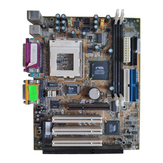
Page 10: Mainboard Layout
Introduction 1-3 Mainboard Layout 1-3 Mainboard Layout 1-3 Mainboard Layout 1-3 Mainboard Layout 1-3 Mainboard Layout 1-4 Connector and Jumper Reference Chart Jumper & Function Page Connector No. Infrared connector WOL (Wake-on-LAN) connector Creative's SB-LINK Sound connector CD-ROM audio in connector AUX audio-in connector Modem Telephony connector Volume control connector... - Page 11 Chapter 1...
-
Page 12: Chapter 2 Hardware Setup
Hardware Setup Chapter 2 Chapter 2 Chapter 2 Chapter 2 Chapter 2 Har d d d d d ware Setup ware Setup ware Setup ware Setup ware Setup If your mainboard has already been installed in your computer you may still need to refer to this chapter if you plan to upgrade your system's hardware. -
Page 13: Installing A Cpu In A Socket 370
Chapter 2 2-2 Installing a CPU in a Socket 370 The Intel Socket 370, designed for the Celeron processor, has been incorporated as a standard mainboard specification To insert your CPU into Socket 370 please do the following: 1. Locate a small dot marked on the top surface of the CPU close to one if it's corners. The same corner will also be cut off, leaving a noticeable notch in the CPU's corner. -
Page 14: Connector And Jumper Settings
Hardware Setup 2-4 Connector and Jumper Settings Connectors are used to link the system board with other parts of the system, including the power supply, the keyboard, and the various controllers on the front panel of the system case. The power supply connector is the last connection to be made while installing a mainboard. -
Page 15: Over-Ride Power Button
Chapter 2 Front Panel Connector Set (J8) A through G A. Over-ride Power Button Connector The power button on the ATX chassis can be used as a normal power switch as well as a device to activate Advanced Power Management Suspend mode. This mode is used for saving electricity when the computer is not in use for long periods of time. - Page 16 Hardware Setup C. Green Switch/Green LED Connector Some ATX cases provide a Green switch which is used to put the system in Suspend mode. In Suspend mode, the power supply to the system is reduced to a trickle, the CPU clock is stopped, and the CPU core is in it's minimum power state.
- Page 17 Chapter 2 Infrared Connector (J1) If you enable the COM2 Mode in BIOS's Integrated Peripherals menu the COM2 port will support IR functions. (See section 3-8) V c c Ir-R x G N D Ir-T x P o w e r su p p ly c o n n . V c c F L O P P Y 1 System/CPU Cooling Fan Connectors...
-
Page 18: Poly-Fuse Over Current Protection
Hardware Setup Clear CMOS Data Jumper (JP1) Normal (default) Clear CMOS data To clear the contents of the CMOS, please follow the steps below. 1.Disconnect the system power supply from the power source. P o w e r su p p ly c o n n . F L O P P Y 1 2.Set the jumper cap at location 2~3 for 5 seconds, then set it back to the default position. - Page 19 Chapter 2 CD-ROM Audio-in Connector(J4) Use the audio cable enclosed with your CD-ROM disk drive to connect the CD-ROM to your mainboard. This will enable your CD-ROM's audio function. G N D P o w e r su p p ly c o n n . F L O P P Y 1 AUX Audio-in Connector(J5) This connector supports AUX Audio input for connecting...
- Page 20 Hardware Setup WOL (Wake-on-LAN) Connector (J2) Enable the Wake Up On LAN selection in BIOS's Power Management Menu to use this function. The capability to remotely manage PCs on a network is a significant factor in reducing administrative and ownership costs. Magic Packet technology is designed to give WOL (Wake- on-LAN) capability to the LAN controller.
- Page 21 Chapter 2 USB(Universal Serial Bus) Ports If you want to use a USB keyboard, you must enable the USB keyboard support function in BIOS's Integrated Peripherals menu (See Section 3-8). USB is an open industry standard, providing a simple and inexpensive way to connect up to 125 devices to a single computer port.
-
Page 22: Main Memory Configuration
Hardware Setup 2-5 Main Memory Configuration The DRAM memory system consists two banks and the memory size ranges from 16~256 MBytes. If you only use one bank it does not matter which one you use and if you use two or more banks, it does not matter which bank you install first. DRAM Specifications DIMM type: 3.3V, 64/72-bit Synchronous DRAM... - Page 23 Chapter 2...
-
Page 24: Chapter 3 Award Bios Setup Program
Award BIOS Setup Program Chapter 3 Chapter 3 Chapter 3 Chapter 3 Chapter 3 3 3 3 3 3 Award BIOS Setup Program Award's BIOS ROM has a built-in setup program that allows users to modify the basic system configuration. This information is stored in CMOS RAM so that it can retain the setup information, even when the power is turned off. -
Page 25: Standard Cmos Setup
User's Manual 3-1 Standard CMOS Setup The Standard CMOS Setup allows users to configure system components such as hard disk drive, floppy disk drive and video display as well as date, time and boot- up error signaling. This configuration menu should be changed when installing a mainboard for the first time, changing hardware in your system such as the HDD, FDD, video display, or when the CMOS data has been lost or contaminated. - Page 26 Award BIOS Setup Program Type (Auto/User/None): Use the fields under the Type column to determine the method you will use to configure the IDE devices. If you choose Auto, BIOS will automatically detect and make optimal settings for most IDE hard drives. The mainboard manufacturer recommends that you choose Auto for all drives.
- Page 27 User's Manual Large - for IDE drives that do not support LBA and have more than 1024 cylinders. Try this setting if your hard disk does not operate properly with the LBA setting. Large mode is not supported by all operating systems, i.e., only certain versions of DOS support large mode.
-
Page 28: Bios Features Setup
Award BIOS Setup Program 3-2 BIOS Features Setup By choosing the BIOS Features Setup option from the CMOS Setup Utility menu (Figure 3-1), the screen below is displayed. This sample screen contains the manufacturer's default values for the mainboard. ROM PCI / ISA BIOS (2A6LGC39) BIOS FEATURES SETUP AWARD SOFTWARE, INC. - Page 29 User's Manual B. Cache Control CPU Internal Cache/External Cache Cache memory is much faster than conventional DRAM system memory. These fields allow you to enable or disable the CPUs Level 1 built-in cache and Level 2 external cache. Both settings are left enabled to significantly increase the performance of your computer.
- Page 30 Award BIOS Setup Program E. Memory Parity/ECC Check If the DRAM chips in your system support parity/ECC check, select Enabled F. Keyboard Interface Typematic Rate Setting When enabled, you can set the following two typematic control items. When disabled, keystrokes are determined arbitrarily by the keyboard controller in your system.
- Page 31 User's Manual Shadowing improves the firmware's performance because the firmware can be read by the CPU through the 16- or 32-bit DRAM bus as opposed to the 8-bit XT bus. However, shadowing also results in reducing the amount of high memory (640 KB to 1 MB) for loading device drivers.
-
Page 32: Chipset Features Setup
Award BIOS Setup Program 3-3 Chipset Features Setup By choosing the Chipset Features Setup option from the CMOS SETUP UTILITY menu(Figure 3-1), the screen below is displayed. This sample screen contains the manufacturer's default values for the mainboard. ROM PCI / ISA BIOS (2A6LGC39) CHIPSET FEATURES SETUP AWARD SOFTWARE, INC. - Page 33 User's Manual B. BANK 0/1 & 2/3 DRAM Timing This item allows youto select the value in this field, depending on whether the board has paged DRAM or EDO (Extended Data Output) DRAMs. C. SDRAM Cycle Length When synchronous DRAM is installed, the number of the clock cycles of CAS latency depends on the DRAM timing.
- Page 34 Award BIOS Setup Program J. Flash BIOS Protection The mainboard manufacturer developed BIOS protection technology that protects the System BIOS from accidental corruption by unauthorized users or computer viruses. When enabled, the BIOS data cannot be changed when attempting to update BIOS with the the FLASH utility.
-
Page 35: Power Management Setup
User's Manual 3-4 Power Management Setup This section provides information on the Green PC power management funtcions. By choosing the Power Management Setup option from the CMOS Setup Utility menu (Figure 3-1), the screen below is displayed. This sample screen contains the ROM PCI / ISA BIOS (2A6LGC39) POWER MANAGEMENT SETUP AWARD SOFTWARE, INC. - Page 36 Award BIOS Setup Program The computer runs in Normal operation mode until the Doze timer expires, at which point the computer enters Doze mode. If no external activity occurs, the computer will go into Standby and Suspend modes when their respective timers expire. If external activity occurs, the computer will wake up from Power Management and return to Normal mode.
- Page 37 User's Manual E. Video Off Method This function serves as both a screen saver and power saver for monitors. See the next function, Video Off After, for setting the video timer. Blank - BIOS will only blank the monitor's screen. The electricity saved in this mode is negligible and this function is only used as a screen saver to prevent screen damage while the screen is on but not in use.
-
Page 38: Power On By Alarm
Award BIOS Setup Program I. Doze Mode The Power Management function must not be set to disabled to enable this function. If no interrupts have occured and the Doze timer expires, system will enter Doze mode. In Doze mode, the CPU clock runs at a lower speed while all other devices operate normaly. - Page 39 User's Manual Q. Power On By Modem When enabled, a modem that receives a call will wake up the system from soft off and green mode. You should connect the modem to the COM port and turn on the resume event in green mode. R.
-
Page 40: Pnp/Pci Configuration
Award BIOS Setup Program 3-5 PNP/PCI Configuration This section provides IRQ and DMA setting information. By choosing the PNP/PCI Configuration option from the CMOS Setup Utility menu (Figure 3-1), the screen below is displayed. This sample screen contains the manufacturer's default values for the mainboard. - Page 41 User's Manual C. Reset Configuration Data When enabled the system BIOS will clear/reset the ESCD during POST. After clearing the ESCD, the BIOS will then change this item's value to Disabled. Otherwise, the ESCD data will become useless. D. IRQ#/DMA# assign to When resources are controlled manually, you can assign each system interrupt &...
-
Page 42: Load Setup Defaults
Award BIOS Setup Program 3-6 Load Setup Defaults Load Setup Defaults loads the default system values directly from the CMOS Setup Utility menu (Figure3-1). If the stored record created by the setup program becomes corrupted and therefore unusable, these defaults will be loaded automatically when you turn on the computer. -
Page 43: Integrated Peripherals
User's Manual 3-7 Integrated Peripherals This section provides information on setting peripheral devices. By choosing the Integrated Peripherals option from the CMOS Setup Utility menu (Figure 3-1), the screen below is displayed. This sample screen contains the manufacturer's default values for the mainboard. ROM PCI / ISA BIOS (2A6LGC39) INTEGRATED PERIPHERALS AWARD SOFTWARE, INC. - Page 44 Award BIOS Setup Program B. Init Display First This function allows user to choose between AGP slot or VGA slot to initialise Display first . C. Onboard Sound Chip This function must be enabled in order to use the onboard audio function. To terminate this function set it to disable.
-
Page 45: Supervisor Password & User Password Setting
User's Manual 3-8 Supervisor Password & User Password Setting There are four different variables that control password settings. The first two are located under the Security Option function in BIOS Features Setup Menu (Figure 3-3). When the Security Option function is set to Setup, a password is required to enter BIOS and change BIOS settings. - Page 46 Award BIOS Setup Program B. Set Both Supervisor Password and User Password Figure 3-10 Set Both Supervisor and User Password...
-
Page 47: Ide Hdd Auto Detection
User's Manual 3-9 IDE HDD Auto Detection This utility can automatically detect IDE hard disk type and parameters. The detection process take about 5 seconds for each physical drive. After the utility detects the disk drive, type Y and press [Enter] to automatically load the parameters in the Hard Disk section of the Standard CMOS Setup menu. - Page 48 Award BIOS Setup Program...
-
Page 49: Chapter 4 Brief Software Driver Guide
Brief Software Driver Guide Chapter 4 Chapter 4 Chapter 4 Chapter 4 Chapter 4 Brief Software Driver Guide The Mainboard Software Guide is found on the CD-ROM that is enclosed with your mainboard and is a PDF file which must be viewed with Adobe's freeware called ®... -
Page 50: Chapter 5 Ess Solo-1 Audio Subsystem
Chapter 4... -
Page 51: Features
Audio Subsystem Chapter 5 Audio Subsystem 5-1 Feature ESS PCI audio Solo-1 (ES1938S-G) subsystem on a single chip. Advance wavetable synthesizer using wavedata on the system memory. Up to 48KHz programable sample rate for record and playback. Intergrated Spatializer 3D effects Processor. Advance power management meets ACPI standards. - Page 52 User's Manual...
- Page 53 Introduction Appendix I Appendix I Appendix I Appendix I Appendix I On Board I/O Addresses & IRQ Maps System Resource I/O Address 1. Timer IRQ0 040, 043 2. Keyboard IRQ1 060, 064 3. Programmable INT IRQ2 0020, 0021, 00A0, 00A1 4.
- Page 54 User's Manual...
Need help?
Do you have a question about the CT-6AIA2 and is the answer not in the manual?
Questions and answers