Table of Contents
Advertisement
Quick Links
© Copyright 2009
EVERTZ MICROSYSTEMS LTD.
5288 John Lucas Drive,
Burlington, Ontario, Canada
L7L 5Z9
Phone:
Sales Fax:
Tech Support Phone:
Tech Support Fax:
Sales:
Tech Support:
Web Page:
Version 1.3 November 2009
The material contained in this manual consists of information that is the property of Evertz Microsystems and is
intended solely for the use of purchasers of the 3405FR. Evertz Microsystems expressly prohibits the use of this
manual for any purpose other than the operation of the device.
All rights reserved. No part of this publication may be reproduced without the express written permission of Evertz
Microsystems Ltd.
Copies of this guide can be ordered from your Evertz products dealer or from Evertz
Microsystems.
3405 Frame Manual
3405FR Fiber Optic SFP Frame
+1 905-335-3700
+1 905-335-3573
+1 905-335-7570
+1 905-335-7571
sales@evertz.com
service@evertz.com
http://www.evertz.com
Advertisement
Table of Contents

Related Manuals for evertz 3405


Summary of Contents for evertz 3405
- Page 1 Version 1.3 November 2009 The material contained in this manual consists of information that is the property of Evertz Microsystems and is intended solely for the use of purchasers of the 3405FR. Evertz Microsystems expressly prohibits the use of this manual for any purpose other than the operation of the device.
- Page 2 This page left intentionally blank...
-
Page 3: Table Of Contents
3405 Frame Manual 3405FR Fiber Optic SFP Frame TABLE OF CONTENTS OVERVIEW............................1 TECHNICAL SPECIFICATIONS ...................... 3 2.1. SYSTEM ..........................3 2.2. COMMUNICATION AND CONTROL ................... 3 2.3. OPTICAL OUTPUT....................... 3 2.4. OPTICAL INPUT........................3 2.5. COMPLIANCE ........................3 2.6. - Page 4 SFP Modules ............10 ® Figure 4-2: 3405FR Front View with Fiber Inputs and Outputs.............. 10 Figure 4-3: Evertz 3405 Series SFP Module Variants ................11 Figure 5-1: 3405FR Fixed Electrical Connections ................. 13 Figure 6-1: 3405T13-2 VistaLINK General Tab..................14 ®...
- Page 5 3405 Frame Manual 3405FR Fiber Optic SFP Frame Tables Table 6-1: LED Status Chart........................18 Table 6-2: LED Chart ..........................19 Table 7-1: VistaLINK Monitoring ......................20 ® Table 7-2: VistaLINK Traps ........................21 ® Table 7-3: VistaLINK Controlled Parameters ..................21 ®...
- Page 6 Nov 09 Information contained in this manual is believed to be accurate and reliable. However, Evertz assumes no responsibility for the use thereof or for the rights of third parties, which may be effected in any way by the use thereof. Any representations in this document concerning performance of Evertz products are for informational use only and are not warranties of future performance, either expressed or implied.
-
Page 7: Overview
3405FR Fiber Optic SFP Frame OVERVIEW The Evertz 3405FR SFP frame is the ideal solution for today's low cost, high density fiber optic distribution needs. The 3405FR provides the flexibility to handle the high-speed requirements of 3G and HDTV as well as SD-SDI, SDTi, DVB-ASI, and Analog. -
Page 8: Figure 1-2: 3405Fr Block Diagram
3405 Frame Manual 3405FR Fiber Optic SFP Frame Figure 1-2: 3405FR Block Diagram Revision 1.3 Page - 2... -
Page 9: Technical Specifications
3405 Frame Manual 3405FR Fiber Optic SFP Frame TECHNICAL SPECIFICATIONS 2.1. SYSTEM Up to 16 or 32 EO, OE, or mixture of EO and OE in a 1RU unit Density: 75 Ω Impedance: BNC per IEC 61169-8 Annex A (F-type connector optional) Connector: 2.2. -
Page 10: 3405Psx External Power Supply Brick
3405 Frame Manual 3405FR Fiber Optic SFP Frame 4 PIN XLR (12V DC) Connector: PSU status LEDs (each per power supply tray) Status Indicators: 5 amp, time delay – 1 per power supply tray Fuses: 2.8. 3405PSX EXTERNAL POWER SUPPLY BRICK... -
Page 11: Mounting
3405 Frame Manual 3405FR Fiber Optic SFP Frame MOUNTING The 3405FR Rack frame requires 1 rack unit (i.e. 1.8 inches (45 mm) of standard 19 inch (483 mm) wide rack space). To firmly fasten the frame to the equipment rack, make sure that all four mounting screws are securely tightened. -
Page 12: Connecting A Secondary Power Supply
3405 Frame Manual 3405FR Fiber Optic SFP Frame Figure 3-2: 3405PSX Power Supply 3.1.1. Connecting a Secondary Power Supply An external redundant power supply (a second model 3405PSX or the backup tray of the 3405PS-6) is available to supply power in case of a failure in the main power supply. Each inlet corresponds to a power supply tray at the front of the frame (3405PST). -
Page 13: Connecting The 1Ru Power Supply Tray (3405Ps-6/+Ps-6 Option)
3405 Frame Manual 3405FR Fiber Optic SFP Frame 3.1.2. Connecting the 1RU Power Supply Tray (3405PS-6/+PS-6 option) The 3405PS-6 frame is an auto-ranging external power supply that automatically senses the input voltage over the range of 100 to 240 VAC. AC Power will need to be applied to both power inlets to ensure redundant operation of the supply and the 3405FR and the 3405PS-6 that it is connected to. -
Page 14: Fan Installation And Removal (3405Fan)
Figure 3-5: 3405PST Status Indicators The power supplies are short circuit protected and should not blow the fuse under a short circuit condition. If there is a fuse failure, contact Evertz customer service regarding the power supply immediately. 3.2. FAN INSTALLATION AND REMOVAL (3405FAN) Figure 3-6 provides an illustration of the 3405FAN front view. -
Page 15: Figure 3-7: Cooling Fan Installation And Removal
3405 Frame Manual 3405FR Fiber Optic SFP Frame Figure 3-7: Cooling Fan Installation and Removal If necessary, the cooling fans can be removed for the purposes of fan replacement. Always ensure that this procedure is applied while the frame is off. Removing the fans will cause unwanted heat build-up in the 3405FR. -
Page 16: Sfp Fiber Module Installation And Removal
3405 Frame Manual 3405FR Fiber Optic SFP Frame SFP FIBER MODULE INSTALLATION AND REMOVAL Figure 4-1 shows the 3405T, 3405R, and 3405OO Evertz SFP modules. ® Figure 4-1: 3405T, 3405R, and 3405OO Evertz SFP Modules ® 4.1. FIBER INPUT AND OUTPUT CONNECTIONS These connections are made using standard LC fiber connector ends on single mode. -
Page 17: Optical Fiber Handling And Care
3405 Frame Manual 3405FR Fiber Optic SFP Frame Figure 4-3: Evertz 3405 Series SFP Module Variants 4.1.1. Optical Fiber Handling and Care The SFP fiber modules are equipped with a class 1 laser and emit invisible radiation. Avoid exposure to the laser emitter and do not stare directly into unconnected SFP emitter ports or fiber ends that are connected to SFP ports. -
Page 18: Installing An Sfp Module
3405 Frame Manual 3405FR Fiber Optic SFP Frame • To prevent dust from entering the apertures of an SFP module, keep plugs inserted into the optical bores. • Do not repeatedly remove and insert SFP modules more often than necessary. -
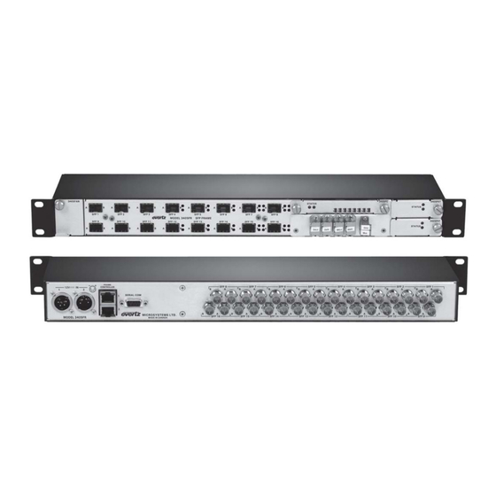
Page 19: Rear Panel Bnc Connections
3405 Frame Manual 3405FR Fiber Optic SFP Frame REAR PANEL BNC CONNECTIONS The BNC’s on the rear of the 3405FR are fixed and correspond to a particular SFP module. These BNC connectors are agile and thus configured as inputs or outputs. A BNC will become an electrical input if its corresponding SFP spigot is an optical transmitter (Electrical to Optical converter). -
Page 20: Configuration And Control
3405 Frame Manual 3405FR Fiber Optic SFP Frame CONFIGURATION AND CONTROL The 3405FC Frame Controller card provides a single point of access to communicate with the VistaLINK ® enabled 3405FR. The 3405FC provides a 10Base-T/100Base-TX Ethernet port and communication is facilitated through the use of Simple Network Management Protocol (SNMP). -
Page 21: Tx/Rx Monitor Tabs
3405 Frame Manual 3405FR Fiber Optic SFP Frame Figure 6-3: 3405OO13-DA4 VistaLINK General Tab ® Displays the type of SFP plugged into a particular slot. SFP Type: Displays the SFP serial number. SFP Serial Number: Displays the current SFP version number. -
Page 22: Faults Tab
3405 Frame Manual 3405FR Fiber Optic SFP Frame Displays the status of the laser in a SFP transmitter module. Laser Status: Displays the wavelength of the SFP transmitter. Wavelength: Displays the optical input power of a SFP receiver. Received Optical Power: 6.1.3. -
Page 23: Trap Destination Tab
3405 Frame Manual 3405FR Fiber Optic SFP Frame The screenshots throughout sections 6.1.4 and 6.1.5 illustrate VistaLINK ® parameters for the 3405FC Frame Controller. 6.1.4. Trap Destination Tab The “Trap Destination” tab enables the user to define the IP address where SNMP traps will be sent to. -
Page 24: Installation And Removal
Description Red LED indicates failure of the power supply, fan or frame controller. The following parameters are monitored by the RED Status LED: 1. 3405 Power Supply unit (blown fuse, short circuit condition) Red LED 2. Failure of the 3405FAN 3. -
Page 25: Sfp Monitoring Leds
3405 Frame Manual 3405FR Fiber Optic SFP Frame 6.2.2. SFP Monitoring LEDs The 16 LEDs on the front of the module signify SFP module presence and signal status (1 through 16). Description An unlit LED signifies that the SFP slot is empty. This indicates that there is no SFP No LED plugged in to the associated port. -
Page 26: Vistalink ® Monitoring/Control
An SNMP manager, also known as a Network Management System (NMS), is a computer running special software that communicates with the devices in the network. Evertz VistaLINK Pro Manager graphical ® user interface (GUI), third party or custom manager software may be used to monitor and control Evertz VistaLINK enabled products. ®... -
Page 27: Vistalink ® Traps
3405 Frame Manual 3405FR Fiber Optic SFP Frame 7.3. VISTALINK TRAPS ® The following traps can be enabled and monitored through the VistaLINK interface. ® Parameter Description Monitors the presence of an electrical input into the TX 1 (Corresponds to A). - Page 28 3405 Frame Manual 3405FR Fiber Optic SFP Frame This page left intentionally blank Revision 1.3 Page - 22...
Need help?
Do you have a question about the 3405 and is the answer not in the manual?
Questions and answers