Sign In
Upload
Manuals
Brands
evertz Manuals
Industrial Equipment
3405FR Series
evertz 3405FR Series Manuals
Manuals and User Guides for evertz 3405FR Series. We have
2
evertz 3405FR Series manuals available for free PDF download: Installation And Operation Manual, Manual
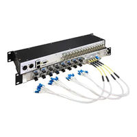
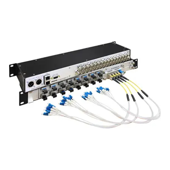
evertz 3405FR Series Installation And Operation Manual (62 pages)
Fiber Optic SFP Frame
Brand:
evertz
| Category:
Industrial Equipment
| Size: 1.81 MB
Table of Contents
Table of Contents
7
Overview
11
Table 1-1: Frame Versions
11
3405Fr-Bnc Frame
12
Figure 1-1: 3405FR-BNC Frame
12
Figure 1-2: 3405FR-BNC Block Diagram
12
3405Fr-Din Frame
13
Figure 1-3: 3405FR-DIN Frame
13
Figure 1-4: 3405FR-DIN Block Diagram
13
3405Fr-Xlink Frame
14
Figure 1-5: 3405FR-XLINK Frame
14
Figure 1-6: 3405FR-XLINK Block Diagram
14
Installation
15
Figure 2-1: External Views of 3405FR-BNC
15
Figure 2-2: External Views of 3405FR-DIN
15
DC Power (12V Versions Only)
16
Figure 2-3: External Views of 3405FR-XLINK
16
Connecting a Redundant Power Supply
17
Connecting the 1RU Power Supply Tray (3405PS-6/+PS-6 Option)
17
Figure 2-4: DC Power Connector to Frame and 3405PS-6
17
Figure 2-5: Locating the External 12V DC Power Connector
17
Figure 2-6: 3405PS-6 Power Supply Tray
18
Connecting the Standalone Power Supply (3405PSX)
19
Figure 2-7: 3405PSX Power Supply
19
DC Power (48Vdc Versions Only)
20
Power Supply Status Indicators
20
Figure 2-8: Locating the External 48V DC Power Connector
20
Figure 2-9: 3405PST Status Indicators
21
Fan Installation and Removal (3405Fan)
22
Cooling
22
Figure 2-10: Front View of 3405FAN
22
Care and Handling of Optical Fiber
23
Safety
23
Assembly
23
Figure 2-11: Cooling Fan Installation and Removal
23
Labeling
24
Handling and Connecting Fibers
24
Figure 2-12: Reproduction of Laser Certification and Identification Label
24
Fiber Input and Output Connections
25
Figure 2-13: 3405FR Front View with Fiber Inputs and Outputs
25
Figure 2-14: 3405T, 3405R, 3405T13-R, and 3405OO13-DA4 Evertz SFP Modules
25
Electro Static Discharge (ESD) Precautions
26
3405FR-BNC SFP Module Variants
26
3405FR-DIN SFP Module Variants
27
3405FR-XLINK SFP Module Variants
28
Installing an SFP Module
28
Removing an SFP Module
29
Electrical Input and Output Connections
29
Rear Panel BNC Connections
29
Rear Panel DIN Connections
30
Rear Panel XLINK Connections
30
Figure 2-16: 3405FR-DIN Fixed Electrical Connections
30
Figure 2-17: 3405FR-XLINK Fixed Electrical Connections
30
3405FR-BNC-48V and 3405FR-DIN-48V Rear Panels
31
Figure 2-18: 3405FR-BNC-48V Rear Panel
31
Figure 2-19: 3405FR-DIN-48V Rear Panel
31
Servicing Instructions
32
Replacing the 3405Ps-6 Power Supply
32
Figure 2-20: Power Supply Retaining Screw
32
Changing the Fuses
33
Technical Specifications
34
3405Fr-Bnc Frame
34
3405Fr-Din Frame
34
3405Fr-Xlink Frame
34
Communication and Control
34
Optical Output
34
Optical Input
35
Electrical Inputs (3405Fr-Bnc & 3405Fr-Din Only)
35
Electrical Outputs (3405Fr-Bnc & 3405Fr-Din Only)
35
Physical
36
Power (12V DC Versions)
36
Power (48V DC)
36
3405Psx External Power Supply Brick
36
3405Ps-6 1Ru Power Supply Tray
36
Compliance
37
Status and Leds
38
Status Led
38
SFP Monitoring Leds
38
Figure 4-1: Front of 3405FC
38
Table 4-1: Status LED Chart
38
Table 4-2: SFP LED Chart
38
Figure 4-2: Front of 3405FC-2
39
Configuration and Control
40
3405 Frame Controller Configuration
40
Vistalink ® Configuration
42
General Tab
42
Figure 5-1: 3405T13-2 Vistalink
42
Figure 5-2: 3405T13-R Vistalink General Tab
42
Figure 5-3: 3405OO13-DA4 Vistalink General Tab
43
Figure 5-4: 3405R-2 Vistalink General Tab
43
Figure 5-5: 3405R-2R Vistalink General Tab
43
TX/RX Configuration Tabs
44
Figure 5-6: 3405T13-2 Vistalink TX Configuration Tab
44
Figure 5-7: 3405T13-R Vistalink TX Configuration Tab
44
Figure 5-8: 3405OO13-DA4 Vistalink RX Configuration Tab
45
Figure 5-9: 3405R-2 Vistalink RX Configuration Tab
45
Tx Configuration
46
Rx Configuration
46
Faults Tab
46
RX Configuration Tab
46
Figure 5-11: 3405T13-2 Vistalink Faults Tab
47
Figure 5-12: 3405T13-R Vistalink Faults Tab
47
Figure 5-13: 3405OO13-DA4 Vistalink Faults Tab
48
Figure 5-14: 3405R-2 Vistalink Faults Tab
48
Network Parameters Tab
49
Figure 5-16: 3405FC Vistalink
49
Network Parameter Tab
49
Faults Tab
49
Trap Destination Tab
50
FC Faults Tab
50
Figure 5-17: 3405FC Vistalink
50
Figure 5-18: 3405FC Vistalink
50
Vistalink
51
Monitoring/Control
51
What Is Vistalink
51
Monitoring
51
Traps
52
Vistalink
52
Controlled Parameters
52
Table 6-2: Vistalink
52
Controlled Parameters
53
Overview
54
3405CWDM Coarse Wavelength Division Multiplexor
54
Table 7-1: Passive Optical Modules
54
Figure 7-1: 3405CWDM-M8 Simplified Block Diagram
55
Figure 7-2: 3405CWDM-M16 Simplified Block Diagram
55
Figure 7-3: 3405CWDM-2-M16 Simplified Block Diagram
56
Figure 7-4: 3405CWDM-2-M8 Simplified Block Diagram
57
Installation
58
Figure 7-5: 8 Channel Breakout Cable
58
Table 7-2: 3405CWDM Model and the Associated Required Fanout Cable
59
Figure 7-6: Wiring Diagram of the 3405CWDM-2-M16 and 3405CWDM-D16
60
Specifications
61
Optical Input/Output
61
Physical
61
Table 7-3: Insertion Loss Specifications
61
Advertisement
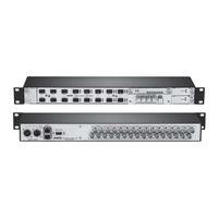
evertz 3405FR Series Manual (28 pages)
Fiber Optic SFP Frame
Brand:
evertz
| Category:
Network Hardware
| Size: 0.76 MB
Table of Contents
Table of Contents
3
Overview
7
Figure 1-1: 3405FR Frame
7
Figure 1-2: 3405FR Block Diagram
8
Technical Specifications
9
System
9
Communication and Control
9
Optical Output
9
Optical Input
9
Compliance
9
Physical
9
Electrical
9
3405Psx External Power Supply Brick
10
3405Ps-6 1Ru Power Supply Tray
10
Mounting
11
Power
11
Figure 3-1: External Views of 3405FR
11
Connecting a Secondary Power Supply
12
Figure 3-2: 3405PSX Power Supply
12
Figure 3-3: Locating the External Power Connector
12
Connecting the 1RU Power Supply Tray (3405PS-6/+PS-6 Option)
13
External Power Supply Connector
13
Power Supply Status Indicators
13
Figure 3-4: DC Power Connector to Frame and 3405PS-6
13
Fan Installation and Removal (3405Fan)
14
Cooling
14
Figure 3-5: 3405PST Status Indicators
14
Figure 3-6: Front View of 3405FAN
14
Figure 3-7: Cooling Fan Installation and Removal
15
Sfp Fiber Module Installation and Removal
16
Fiber Input and Output Connections
16
Figure 4-1: 3405T, 3405R, and 3405OO Evertz SFP Modules
16
Figure 4-2: 3405FR Front View with Fiber Inputs and Outputs
16
Optical Fiber Handling and Care
17
Figure 4-3: Evertz 3405 Series SFP Module Variants
17
Installing an SFP Module
18
Removing an SFP Module
18
Rear Panel Bnc Connections
19
Figure 5-1: 3405FR Fixed Electrical Connections
19
Configuration and Control
20
Vistalink Configuration
20
General Tab
20
Figure 6-1: 3405T13-2 Vistalink ® General Tab
20
Figure 6-2: 3405R-2 Vistalink ® General Tab
20
TX/RX Monitor Tabs
21
Figure 6-3: 3405OO13-DA4 Vistalink ® General Tab
21
Figure 6-5: 3405R-2 Vistalink RX Monitor Tab
21
TX Monitor Tab
21
Figure 6-6: 3405OO13-DA4 Vistalink ® RX Monitor Tab
21
Faults Tab
22
Figure 6-7: 3405T13-2 Vistalink ® Faults Tab
22
Figure 6-8: 3405R-2 Vistalink Faults Tab
22
Figure 6-9: 3405OO13-DA4 Vistalink Faults Tab
22
Trap Destination Tab
23
FC Faults Tab
23
Figure 6-10: 3405FC Vistalink ® Trap Destination Tab
23
Figure 6-11: 3405FC Vistalink ® FC Faults Tab
23
Installation and Removal
24
Status Led
24
Figure 6-12: Front of 3405FC
24
Table 6-1: LED Status Chart
24
SFP Monitoring Leds
25
Figure 6-13: Front of 3405FC-2
25
Table 6-2: LED Chart
25
Vistalink ® Monitoring/Control
26
What Is Vistalink
26
Vistalink ® Monitored Parameters
26
Table 7-1: Vistalink
26
Vistalink ® Traps
27
Vistalink ® Controlled Parameters
27
Table 7-2: Vistalink Traps
27
Table 7-3: Vistalink ® Controlled Parameters
27
Advertisement
Related Products
evertz 3405FR-BNC
evertz 3405
evertz 3405FRS-BNC
evertz 3406FR-HDBNC
evertz 3400 Series
evertz 3480DEC18-MP2SD-ASI18
evertz 3410 Multivert
evertz 3025EMC
evertz 3067VIP-3G-36x4
evertz 3700FR-IP-48VDC
evertz Categories
Media Converter
Network Hardware
Amplifier
Transmitter
Receiver
More evertz Manuals
Login
Sign In
OR
Sign in with Facebook
Sign in with Google
Upload manual
Upload from disk
Upload from URL