Table of Contents
Advertisement
Quick Links
3405 Standalone Frame Manual
© Copyright 2011
EVERTZ MICROSYSTEMS LTD.
5288 John Lucas Drive,
Burlington, Ontario, Canada
L7L 5Z9
Phone:
Sales Fax:
Tech Support Phone:
Tech Support Fax:
Sales:
Tech Support:
Web Page:
Version 1.1, June 2011
The material contained in this manual consists of information that is the property of Evertz Microsystems and is
intended solely for the use of purchasers of the 3405FRS-BNC. Evertz Microsystems expressly prohibits the use of
this manual for any purpose other than the operation of the device.
All rights reserved. No part of this publication may be reproduced without the express written permission of Evertz
Microsystems Ltd.
Copies of this guide can be ordered from your Evertz products dealer or from Evertz
Microsystems.
3405FRS-BNC - Fiber Optic SFP Frame
+1 905-335-3700
+1 905-335-3573
+1 905-335-7570
+1 905-335-7571
sales@evertz.com
service@evertz.com
http://www.evertz.com
Advertisement
Table of Contents

Related Manuals for evertz 3405


Summary of Contents for evertz 3405
- Page 1 Version 1.1, June 2011 The material contained in this manual consists of information that is the property of Evertz Microsystems and is intended solely for the use of purchasers of the 3405FRS-BNC. Evertz Microsystems expressly prohibits the use of this manual for any purpose other than the operation of the device.
- Page 2 This page left intentionally blank...
-
Page 3: Table Of Contents
REAR PANEL BNC CONNECTIONS ................... 12 CONFIGURATION AND CONTROL ..................... 13 6.1. CONFIGURING THE ON BOARD FRAME CONTROLLER ..........13 6.1.1. 3405 Serial I/O Connections .................. 13 6.1.2. Terminal Program Setup ..................13 6.2. 3405 FRAME CONTROLLER CONFIGURATION ............. 14... - Page 4 3405 Frame Manual 3405FRS-BNC Fiber Optic SFP Frame 6.3. VISTALINK CONFIGURATION ..................15 ® 6.3.1. General Tab ......................16 6.3.2. TX/RX Configuration Tabs ..................18 6.3.2.1. Tx Configuration..................20 6.3.2.2. Rx Configuration ..................20 6.3.3. Faults Tab ......................21 6.3.4. Network Parameter Tab ..................23 6.3.5.
- Page 5 SFP Modules ......8 ® Figure 4-2: 3405FRS-BNC Front View with Fiber Inputs and Outputs ............ 8 Figure 4-3: Evertz 3405 Series SFP Module Variants ................9 Figure 5-1: 3405FRS-BNC Fixed Electrical Connections ..............12 Figure 6-1: 3405T13-2 VistaLINK General Tab .................. 16 ®...
- Page 6 June 2011 Information contained in this manual is believed to be accurate and reliable. However, Evertz assumes no responsibility for the use thereof or for the rights of third parties, which may be effected in any way by the use thereof. Any representations in this document concerning performance of Evertz products are for informational use only and are not warranties of future performance, either expressed or implied.
-
Page 7: Overview
3G and HDTV, as well as SD-SDI, SDTi, and DVB-ASI. The 3405FRS-BNC is designed on a standalone frame to house up to 4 hot swappable Evertz SFP modules. This provides up to 8 EO or 8 OE in a standalone frame. The frame can be configured for a mixture of modules. -
Page 8: Figure 1-2: 3405Frs-Bnc Block Diagram
3405 Frame Manual 3405FRS-BNC Fiber Optic SFP Frame Serial I/O Serial I/O Serial I/O Serial I/O Local Indication Control/ Indication VistaLINK Interface 110-220V 110-220V Micro DB9 Optical I/O Optical I/O Optical I/O Optical I/O SFP’s 1 - 4 Figure 1-2: 3405FRS-BNC Block Diagram Page - 2 Revision 1.1... -
Page 9: Technical Specifications
3405 Frame Manual 3405FRS-BNC Fiber Optic SFP Frame TECHNICAL SPECIFICATIONS 2.1. SYSTEM Density: Up to 8 EO, OE, or mixture of EO and OE in a miniature frame 75 Ω Impedance: Connector: BNC per IEC 61169-8 Annex A 2.2. COMMUNICATION AND CONTROL... -
Page 10: Electrical Inputs
3405 Frame Manual 3405FRS-BNC Fiber Optic SFP Frame 2.6. ELECTRICAL INPUTS Reclocked Standard: SMPTE 424M (3Gb/s), SMPTE 292M (1.5Gb/s), SMPTE 259M (270Mb/s), DVB-ASI Connector: BNC per IEC 61169-8 Annex A Equalization: Automatic to 80m @ 3Gb/s, 100m @ 1.5Gb/s, 250m @ 270Mb/s (with... -
Page 11: Mounting
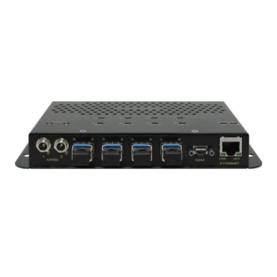
3405 Frame Manual 3405FRS-BNC Fiber Optic SFP Frame MOUNTING The 3405FRS-BNC standalone frame has 4 mounting holes. They are separated 2” vertically, and 6.56” horizontally. To firmly fasten, make sure that all four mounting screws are securely tightened. Figure 3-1: External Views of 3405FRS-BNC 3.1. -
Page 12: Connecting A Secondary Power Supply
3405 Frame Manual 3405FRS-BNC Fiber Optic SFP Frame 3.1.1. Connecting a Secondary Power Supply A redundant power supply is available to provide power in case of a failure in the main power supply. Power should be applied by connecting a coaxial power supply connector cord to the second power entry module on the front panel (12VDC 2). -
Page 13: Power Supply Status Indicators
Figure 3-4: Power Supply Status Indicators The power supplies are short circuit protected and should not blow the fuse under a short circuit condition. If there is a fuse failure, contact Evertz customer service regarding the power supply immediately. CAUTION: To achieve adequate cooling, care should be taken to ensure that exhaust openings are free of obstructions. -
Page 14: Sfp Fiber Module Installation And Removal
3405 Frame Manual 3405FRS-BNC Fiber Optic SFP Frame SFP FIBER MODULE INSTALLATION AND REMOVAL Figure 4-1 depicts any one of the following Evertz SFP modules: 3405T13-2, 3405Txx/yy-2, 3405R-2, ® 3405R-2R, 3405OO13-DA4, and 3405OOxx-DA4. Figure 4-1: 3405T, 3405R, 3405T13-R, and 3405OO13-DA4 Evertz SFP Modules ®... -
Page 15: 3405Frs-Bnc Sfp Module Variants
3405 Frame Manual 3405FRS-BNC Fiber Optic SFP Frame 4.1.1. 3405FRS-BNC SFP Module Variants Figure 4-3: Evertz 3405 Series SFP Module Variants Page - 9 Revision 1.1... -
Page 16: Optical Fiber Handling And Care
3405 Frame Manual 3405FRS-BNC Fiber Optic SFP Frame 4.1.2. Optical Fiber Handling and Care The SFP fiber modules are equipped with a class 1 laser and emit invisible radiation. Avoid exposure to the laser emitter and do not stare directly into unconnected SFP emitter ports or fiber ends that are connected to SFP ports. -
Page 17: Removing An Sfp Module
3405 Frame Manual 3405FRS-BNC Fiber Optic SFP Frame Note: Do not remove the dust plugs from the optical bores of the SFP or the dust caps from the fiber-optic cable until you are ready to connect the cable. The plugs and caps protect the SFP optical ports and the cable connectors from contamination. -
Page 18: Rear Panel Bnc Connections
3405 Frame Manual 3405FRS-BNC Fiber Optic SFP Frame REAR PANEL BNC CONNECTIONS The BNC’s on the rear of the 3405FRS-BNC are fixed and correspond to a particular SFP module. These BNC connectors are agile and thus configured as inputs or outputs. A BNC will become an electrical input if its corresponding SFP spigot is an optical transmitter (Electrical to Optical converter). -
Page 19: Configuration And Control
486 PC or better with a 16550 UART based communications port is recommended. • Terminal program such as HyperTerminal 6.1.1. 3405 Serial I/O Connections Serial I/O: A 9 pin female Micro DB9 connector for connection to a computer. Pin #... -
Page 20: 3405 Frame Controller Configuration
1) From the main menu, there are two selections available: <<<S-3405 Menu Engine V0.1>>> 3405 Controller Settings SFP Module Settings 2) If menu item #1 3405 Controller Settings is selected, the following items will be available: <<<S-3405 Menu Engine V0.1>>> View Network Settings -Displays current network settings... -
Page 21: Vistalink Configuration
3405 Frame Manual 3405FRS-BNC Fiber Optic SFP Frame 3405R2 <<<S-3405 Menu Engine V0.1>>> Display SFP Status -Displays SFP status parameters Display SFP Serial Number -Displays SFP serial number Display SFP Error Message -Displays SFP error message Set RX Automute -Sets output squelch mode... -
Page 22: General Tab
3405 Frame Manual 3405FRS-BNC Fiber Optic SFP Frame 6.3.1. General Tab The “General” tab enables the user to view the status of various parameters such as SFP Type, Serial Number, and SFP Firmware Version. Figure 6-1: 3405T13-2 VistaLINK General Tab ®... -
Page 23: Figure 6-4: 3405R-2 Vistalink
3405 Frame Manual 3405FRS-BNC Fiber Optic SFP Frame Figure 6-4: 3405R-2 VistaLINK General Tab ® Figure 6-5: 3405R-2R VistaLINK General Tab ® • SFP Type: Displays the type of SFP plugged into a particular slot. • SFP Serial Number: Displays the SFP serial number. -
Page 24: Tx/Rx Configuration Tabs
3405 Frame Manual 3405FRS-BNC Fiber Optic SFP Frame 6.3.2. TX/RX Configuration Tabs The “TX Configuration” tab displays the current Laser Status, Wavelength, SFP Status, and Reclocker Status. It also allows the user to set Squelch mode. The “RX Configuration” tab displays the Received Optical Power and Reclocker Status. It also allows the user to set an Optical Input Power Threshold, Inversion mode, Slew Rate mode, Squelch Mode, and Swap Channel mode. -
Page 25: Figure 6-8: 3405Oo13-Da4 Vistalink Rx Configuration Tab
3405 Frame Manual 3405FRS-BNC Fiber Optic SFP Frame Figure 6-8: 3405OO13-DA4 VistaLINK RX Configuration Tab ® Figure 6-9: 3405R-2 VistaLINK RX Configuration Tab ® Page - 19 Revision 1.1... -
Page 26: Tx Configuration
3405 Frame Manual 3405FRS-BNC Fiber Optic SFP Frame Figure 6-10: 3405R-2R VistaLINK RX Configuration Tab ® 6.3.2.1.Tx Configuration • Laser Status: Displays the status of the laser in a SFP transmitter module. • Wavelength: Displays the wavelength of the SFP transmitter. -
Page 27: Faults Tab
3405 Frame Manual 3405FRS-BNC Fiber Optic SFP Frame 6.3.3. Faults Tab The “Faults” tab allows the user to enable a variety of traps. To enable a particular trap, simply click the box located beside each trap so that a check-mark appears. When a check-mark is present, the trap is enabled. -
Page 28: Figure 6-13: 3405Oo13-Da4 Vistalink Faults Tab
3405 Frame Manual 3405FRS-BNC Fiber Optic SFP Frame Figure 6-13: 3405OO13-DA4 VistaLINK Faults Tab ® Figure 6-14: 3405R-2 VistaLINK Faults Tab ® Page - 22 Revision 1.1... -
Page 29: Network Parameter Tab
3405 Frame Manual 3405FRS-BNC Fiber Optic SFP Frame Figure 6-15: 3405R-2R VistaLINK Faults Tab ® The screenshots throughout sections 6.3.4 and 6.3.5 illustrate VistaLINK ® parameters for the 3405FRS-BNC. 6.3.4. Network Parameter Tab The “Network” parameter tab enables the user to define the network parameters of the 3405SFR frame. -
Page 30: Trap Destination Tab
3405 Frame Manual 3405FRS-BNC Fiber Optic SFP Frame 6.3.5. Trap Destination Tab The “Trap Destination” tab enables the user to define the IP address of the destination to where SNMP traps will be sent. Figure 6-17: 3405FC VistaLINK Trap Destination Tab ®... -
Page 31: Vistalink ® Monitoring/Control
An SNMP manager, also known as a Network Management System (NMS), is a computer running special software that communicates with the devices in the network. Evertz VistaLINK Pro Manager graphical ® user interface (GUI), third party or custom manager software may be used to monitor and control Evertz VistaLINK enabled products. ®... -
Page 32: Vistalink
3405 Frame Manual 3405FRS-BNC Fiber Optic SFP Frame 7.3. VISTALINK TRAPS ® The following traps can be enabled and monitored through the VistaLINK interface. ® Parameter Description Monitors high optical input on channel 1. Rx Optical Power High 1 Rx Optical Power High 2 Monitors high optical input on channel 2.
Need help?
Do you have a question about the 3405 and is the answer not in the manual?
Questions and answers