Table of Contents
Advertisement
Quick Links
Advertisement
Table of Contents

Related Manuals for THORLABS Chromatis


Summary of Contents for THORLABS Chromatis
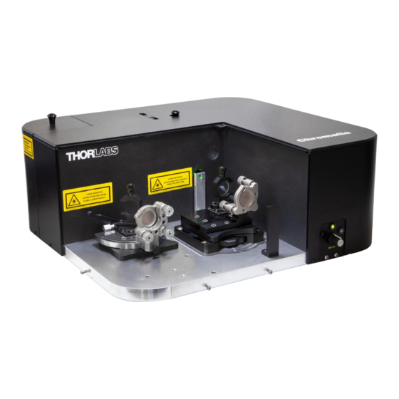
- Page 1 Chromatis™ Dispersion Measurement System User Guide...
-
Page 2: Table Of Contents
Chromatis™ Dispersion Measurement System Table of Contents Chapter 1 Safety ......................... 1 Chapter 2 Description ......................... 3 Chapter 3 Instrument Overview ....................5 Chapter 4 Measurement ......................8 4.1.1 Zero-Degree Reflection and Transmission Fixture (Ø1” and Ø1/2” Optics) ............9 4.1.2... -
Page 3: Chapter 1 Safety
Chromatis™ Dispersion Measurement System Chapter 1: Safety Chapter 1 Safety Warning All statements regarding safety of operation and technical data in the manual will only apply when the unit is operated correctly as it was designed for. Laser Radiation Warning The user may be exposed to laser signals after they have been attenuated via internal components to <... - Page 4 Opening the device will void your warranty. Any modification or servicing of this system by unqualified personnel renders Thorlabs free of any liability. This device can only be returned when packaged into the complete original packaging, including all foam packing inserts.
-
Page 5: Chapter 2 Description
Chapter 2: Description Chapter 2 Description The Chromatis is a white light interferometer (WLI) designed to measure the dispersion characteristics of reflective and transmissive optics. The WLI itself can be implemented as a simple interferometer as shown in Figure 1. Figure 1... - Page 6 360 nm. The typical configuration of the Chromatis system includes a silicon detector, which can measure from 500 nm to 1100 nm. For NIR applications, a InGaAs detector operating over the 900 nm to 1650 nm wavelength is also available separately.
-
Page 7: Chapter 3 Instrument Overview
Instrument Overview Optical Head and Fixtures The Chromatis instrument is designed to be easy to use. There are two separate user-swappable fixtures available that enable three different measurement types for Ø1/2” and Ø1” optics, which are discussed in the next chapter. - Page 8 There is a power switch in the back of the power supply enclosure (Figure 5) that should remain on unless the instrument is being moved or the bulb is being replaced. When the Chromatis system is not in use,...
- Page 9 Input (SMA Connector) Figure 5 Chromatis power supply front (upper picture) and back (lower picture) panels. The power supply on-off switch is next to the power cord plug. The umbilical cables plug into the Fiber Out and Power Out ports.
-
Page 10: Chapter 4 Measurement
Measurement Alignment and Fixture Overview The Chromatis dispersion measurement system is designed to enable easy and fast measurements of mirrors and transmissive optics in three different modes of operation: zero-degree reflection, transmission, and angled reflection. The included fixtures are mechanically registered and easily swappable. There are two separate fixtures that provide these different measurements, as described below. -
Page 11: Zero-Degree Reflection And Transmission Fixture (Ø1" And Ø1/2" Optics)
Chromatis™ Dispersion Measurement System Chapter 4: Measurement Warning: When changing out fixtures, ensure that the instrument On/Off switch is in the OFF position to disable laser light from the aperture. 4.1.1 Zero-Degree Reflection and Transmission Fixture (Ø1” and Ø1/2” Optics) -
Page 12: Angle Of Incidence Reflection Fixture
Chromatis™ Dispersion Measurement System Chapter 4: Measurement 4.1.2 Angle of Incidence Reflection Fixture Mirror Under Test Angle scale System Optic Figure 9 Fixture for the measurement of a reflective optic at a user-defined angle of incidence. The optic is placed in a front-surface-registered mount (black) and the angle of incidence is read off of the scale on the rotation stage. - Page 13 Optical Alignment with Software Guidance The Chromatis software is designed to guide the user through each type of measurement in a step-by-step way. The main software home screen has options for the four types of measurements. Please note that the fixture required for the mirror pair measurement is not included with the Chromatis dispersion measurement system.
- Page 14 This will minimize the exposure to the Class II laser sources exiting the aperture into the measurement area. 2. Place the correct fixture and optic in the Chromatis optical head, then turn the instrument switch back to On to re-enable the light sources.
- Page 15 Chromatis™ Dispersion Measurement System Chapter 4: Measurement Figure 13 Alignment Instructions: An animation on the right-hand side shows what the fringes should look like when close to optimum alignment while the picture on the left shows which alignment knobs to adjust. If visual alignment is too difficult for a user, “Oscilloscope Alignment”...
- Page 16 Chromatis™ Dispersion Measurement System Chapter 4: Measurement Figure 15 Find Zero Results Popup Screen: This screen allows the user to determine if the zero-delay position has been found correctly. At zero delay, the white light will interfere, causing detectable oscillations.
- Page 17 Chromatis™ Dispersion Measurement System Chapter 4: Measurement whole interference pattern. In general, the smaller the time range, the smaller the noise. High dispersion optics generally require 500 to 2000 fs to capture the whole interference pattern. There is not one time range setting that is optimal for every optic.
- Page 18 Chromatis™ Dispersion Measurement System Chapter 4: Measurement Figure 19 Two more interference patterns with appropriate time delays. The left graph shows the interference pattern for a 3 mm thick piece of fused silica for a Time Range of 800 fs. The right graph shows a chirped mirror designed for the visible at a 500 fs Time Range.
- Page 19 Chromatis™ Dispersion Measurement System Chapter 4: Measurement programs. Saved along with the .CSV file is a .TXT file containing any user-specified notes as well as the scan settings for that data set. Clicking “Create Report” opens a screen where the user can select six graphs for display at one time (Figure 22).
-
Page 20: Configuration Settings Tab
Chapter 4: Measurement Optical Alignment Without Software Guidance The Chromatis software provides step-by-step instructions for how to align each measurement fixture for the current optic under test. However, you can choose to use the advanced panel to make measurements without step-by-step instructions (Figure 23). - Page 21 Detector: Allows the user to select which detector is in use so that the program uses the correct calibration file. Note that silicon detectors come standard with the Chromatis system, and CHRDETN InGaAs detectors are available for purchase separately.
-
Page 22: Motor Control Tab
Chromatis™ Dispersion Measurement System Chapter 4: Measurement 4.3.2 Motor Control Tab Figure 25 Motor Control Tab: The user can manually move the motor and watch the photodetector signals live. The motor control tab lets the user watch the photodiode signals while manually moving the motor. The user can run the Find Zero process, set the zero position manually, go to a location, and bump the motor arbitrary steps in either the forward or backward directions. -
Page 23: P-Polarization Tab
Chromatis™ Dispersion Measurement System Chapter 4: Measurement 4.3.4 P-Polarization Tab Figure 27 P-Polarization Tab: The data from the P-polarization detector is displayed in this tab. The P-polarization tab displays data from the P-polarization detector. There are six graphs displaying various information. -
Page 24: Chapter 5 Reference Optics And Calibration
Chapter 5: Reference Optics and Calibration Chapter 5 Reference Optics and Calibration The Chromatis dispersion measurement system is provided with reference optics so that the user can verify the instrument is working as it was at the factory. Measurement Mode... -
Page 25: Chapter 6 Wavelength Selection Filters And Detector Gain Settings
The detector depicted in this figure has the gain set to 70 dB, as indicated by the notch. The Chromatis dispersion measurement system comes standard with three filters for the included silicon detectors. There are six total filter positions available, so two more filter positions are available for future use (one position needs to remain open to let all the light through). - Page 26 CHRDETN InGaAs Detector, No Filter, 50 dB Gain Figure 30 The normalized system response of the Chromatis system with a silver mirror in the test arm. This graph shows the normalized power spectral density of the instrument at each filter setting, which includes the detector sensitivity, light source output spectrum, beamsplitter performance, system mirror reflectivity, and polarizer transmission.
-
Page 27: Chapter 7 Changing Detectors
Chapter 7 Changing Detectors The silicon detectors in the Chromatis optical head can be replaced with the CHRDETN InGaAs detectors for NIR applications. To switch between the two detector modules, follow this procedure: 1. Turn the instrument head Off with the On/Off switch on the side of the instrument. This will disable laser light from exiting the photodiode aperture. - Page 28 Chromatis™ Dispersion Measurement System Chapter 7: Changing Detectors Power Power Signal Signal Figure 32 Top view of the detector electrical and signal connections. Unscrew the power connectors from each photodiode and disconnect the BNC signal cables before removing the detector module. Make sure the signal cables remain in the same relative positions when re-attaching them to the detectors.
-
Page 29: Chapter 8 Specifications
For a Low Dispersion Optic To accommodate non-standard optic sizes or mirror pair measurements, please contact applications@thorlabs.com The InGaAs detector module (Item # CHRDETN) is not included with the Chromatis dispersion measurement system and must be purchased separately as an accessory. -
Page 30: Chapter 9 Mechanical Drawings
Chromatis™ Dispersion Measurement System Chapter 9: Mechanical Drawings Chapter 9 Mechanical Drawings Figure 35 Chromatis Optical Head Mechanical Drawing Page 28 TTN202268-D02... - Page 31 Chromatis™ Dispersion Measurement System Chapter 9: Mechanical Drawings Figure 36 Chromatis Power Supply Mechanical Drawing Rev. A, September 27, 2022 Page 29...
-
Page 32: Chapter 10 Certifications And Compliance
Chromatis™ Dispersion Measurement System Chapter 10: Certifications and Compliance Chapter 10 Certifications and Compliance Page 30 TTN202268-D02... -
Page 33: Chapter 11 Warranty And Rma Information
Waste treatment is your own responsibility. “End of life” units must be returned to Thorlabs or handed to a company specializing in waste recovery. Do not dispose of the unit in a litter bin or at a public waste disposal site. It is the user’s responsibility to delete all private data stored on the device prior to disposal. -
Page 34: Chapter 12 Thorlabs Worldwide Contacts
Chromatis™ Dispersion Measurement System Chapter 12: Thorlabs Worldwide Contacts Chapter 12 Thorlabs Worldwide Contacts For technical support or sales inquiries, please visit us at for our most up-to-date www.thorlabs.com/contact contact information. USA, Canada, and South America UK and Ireland Thorlabs, Inc. - Page 36 www.thorlabs.com...
Need help?
Do you have a question about the Chromatis and is the answer not in the manual?
Questions and answers