Table of Contents
Advertisement
Quick Links
Advertisement
Table of Contents

Related Manuals for Elation KL SPOT IP


Summary of Contents for Elation KL SPOT IP
- Page 1 SPOT IP User Manual...
- Page 2 Elation Professional B.V. | Junostraat 2 | 6468 EW Kerkrade, The Netherlands +31 45 546 85 66 | +31 45 546 85 96 fax | www.elationlighting.eu | info@elationlighting.eu Elation Professional Mexico | AV Santa Ana 30 | Parque Industrial Lerma, Lerma, Mexico 52000 +52 (728) 282-7070...
-
Page 3: Table Of Contents
C O N T E N T S General Information IP65 Rated Limited Warranty (USA Only) Safety Guidelines Overview Gobos & Gobo Wheels Gobo Installation - Rotating Gobo Wheel Gobo Dimensions Framing Module Installation (Optional) Torque Settings for Screws Fan Modes and Low Noise Operation Installation Guidelines Remote Device Management (RDM) System Menu/Service Port Update Instructions... - Page 4 Please do not discard the shipping carton in the trash. Please recycle whenever possible. BOX CONTENTS Power Cable (x1) CUSTOMER SUPPORT Contact ELATION Service for any product related service and support needs. Also visit forums.elationlighting.com with questions, comments, or suggestions.
-
Page 5: Ip65 Rated
I P 6 5 R AT E D The International Protection (IP) rating system is commonly expressed as “IP” (Ingress Protection) followed by two numbers (i.e. IP65), where the numbers define the degree of protection. The first digit (Foreign Bodies Protection) indicates the extent of protection against particles entering the fixture, and the second digit (Water Protection) indicates the extent of protection against water entering the fixture. -
Page 6: Limited Warranty (Usa Only)
It is the owner’s responsibility to establish the date and place of purchase by acceptable evidence, at the time service is sought. B. For warranty service, send the product only to the Elation Professional factory. All shipping charges must be pre-paid. If the requested repairs or service (including parts replacement) are within the terms of this warranty, Elation Professional will pay return shipping charges only to a designated point within the United States. -
Page 7: Safety Guidelines
S A F E T Y G U I D E L I N E S This fixture is a sophisticated piece of electronic equipment. To guarantee smooth operation, it is important to follow all instructions and guidelines in this manual. Elation Professional is not responsible for injury and/or damages resulting from the misuse of this fixture due to the disregard of the information printed in this manual. - Page 8 S A F E T Y G U I D E L I N E S For Your Own Personal Safety, Please Read and Understand This Manual Completely Before You Attempt To Install Or Operate This Unit! • Do not touch the fixture housing during operation, as it may be hot. •...
-
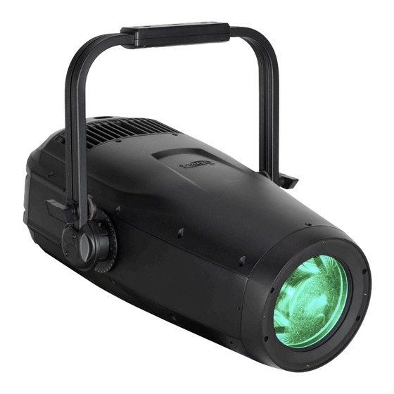
Page 9: Overview
O V E R V I E W Mounting Yoke Lens Mounting Holes Fuse: T5A/250V IP65 Locking Power In/Out Valve Control Panel IP65 5pin DMX In/Out... -
Page 10: Gobos & Gobo Wheels
G O B O S & G O B O W H E E L S ROTATING GOBO WHEEL Pos. 1 Pos. 2 Pos. 3 Pos. 4 Pos. 5 Pos. 6 FIXED GOBO WHEEL Pos. 1 Pos. 2 Pos. 3 Pos. - Page 11 G O B O S & G O B O W H E E L S Rotating Gobo Wheel Pos. 4 Pos. 3 Pos. 5 Pos. 2 Pos. 6 Pos. 1 Fixed Gobo Wheel Pos. 4 Pos. 5 Pos. 3 Pos.
-
Page 12: Gobo Installation - Rotating Gobo Wheel
G O B O I N S TA L L AT I O N - R O TAT I N G G O B O W H E E L Open the top cover of the fixture and locate the rotating gobo wheel module. Remove the screws that secure it to the internal housing frame, then carefully remove it and set it aside. - Page 13 G O B O I N S TA L L AT I O N - R O TAT I N G G O B O W H E E L Locate the Rotating GOBO being replaced. Carefully press the GOBO Holder up to clear the frame, then pull it out and away until it fully clears the Fixed GOBO Wheel.
-
Page 14: Gobo Dimensions
Extended testing of custom gobo designs is highly recommended prior to use. Contact ELATION SERVICE for further information: Ø2.5mm... - Page 15 F R A M I N G M O D U L E I N S TA L L AT I O N Open the top cover of the fixture and locate the framing module placeholder. Remove the framing module placeholder and replace it with the new framing module, then reinstall the top cover.
-
Page 16: Torque Settings For Screws
Fix Head Back Cover (10±0.5/Kgf.cm) Fix Heatsink Cover (5±0.5/Kgf.cm) TO CONFIRM THE IP65 INTEGRITY AFTER OPENING COVER, TEST FIXTURE USING THE ELATION IP TESTER. CONTACT ELATION SERVICE FOR MORE DETAILS. IP PRESSURE TESTING PARAMETERS Parameter Value Maximum Pressure 2.3psi (23.0 KPa) Minimum Pressure 2.9psi (20.0 KPa) - Page 17 FAN CONTROL AND LOW NOISE OPERATION The KL Spot IP is a high-performance fixture suited for multiple applications. For noise critical environments such as Theater, Opera, or Orchestral Halls, it offers various fan operation modes which remove unwanted noise distractions for the audience and performers. Fan Modes can be changed remotely via the DMX control channel, allowing the fixture to offer high output or whisper-silent operation at a moment’s notice.
-
Page 18: Installation Guidelines
I N S TA L L AT I O N G U I D E L I N E S FLAMMABLE MATERIAL WARNING Keep fixture minimum 5.0 feet (1.5m) away from flammable materials and/or pyrotechnics. ELECTRICAL CONNECTIONS A qualified electrician should be used for all electrical connections and/or installations. - Page 19 SAFETY CABLE of the appropriate safety rating to the safety cable rigging point. The KL Spot IP has a thicker 30mm yoke to provide greater positional stability to the fixture. However, because of this increased thickness, the bolts usually provided for most theatrical clamps are not long enough to provide sufficient threads to securely attach a washer and locking nut.
- Page 20 FIXTURE INSTALLATION The Elation KL SPOT IP is fully operational in three different mounting positions, hanging upside-down, mounted sideways on trussing, or set on a flat level surface. Be sure this fixture is kept at least 0.2m (7.9in.) away from any flammable materials (decoration etc.). Always use and install the supplied safety cable as a safety measure to prevent accidental damage and/or injury in the event the clamp fails.
- Page 21 LEDs. This issue is not specific only to ELATION lighting fixtures, it is a common issue with lighting fixtures from all manufacturers. Although there is no true way to fully prevent this issue from happening, the guidelines below can prevent any potential damage from occurring if followed.
-
Page 22: Remote Device Management (Rdm)
R E M O T E D E V I C E M A N A G E M E N T ( R D M ) NOTE: In order for RDM to work properly, RDM enabled equipment must be used throughout the entire system, including DMX data splitters and wireless systems. -
Page 23: System Menu/Service Port Update Instructions
MODE button for 3 seconds. A copy of the latest software can be obtained by contacting Elation Support. AN ELATION C-LOADER II CAN ALSO BE USED TO UPDATE THE FIXTURE TO THE LATEST SOFTWARE. To order this device, please contact Elation Support for further details. - Page 24 S YS T E M M E N U MAIN MENU OPTIONS / VALUES (Default Settings in BOLD) DMX Address 001 - 512 Standard Extended DMX Mode RGB Extended DMX SETTINGS CMY Extended Hold Last No DMX Status Fade to Black Standalone Dimmer Dimmer 0% - 100%...
- Page 25 S YS T E M M E N U MAIN MENU OPTIONS / VALUES (Default Settings in BOLD) Life Time Last Run Time Time Reset Passcode=038 Current Temperature Max Resettable Reset Passcode=038 INFORMATION DMX Values Green Product IDs RDM UID Fixture Errors Error Codes Reset Error Log...
-
Page 26: Dimmer Modes & Curves
D I M M E R M O D E S & C U R V E S... -
Page 27: Dmx Traits
D M X T R A I T S Default Standard Extended RGB Function Snap Extended Extended Values Value 0-255 0 → 100% Red Fine 0-255 Fine Adjustment Green 0-255 0 → 100% Green Fine 0-255 Fine Adjustment Blue 0-255 0 →... - Page 28 D M X T R A I T S Default Standard Extended RGB Function Snap Extended Extended Values Value Color Open 1-179 Virtual Swatch Book (See Sheet) Scroll 180-201 Clockwise Fast → Slow 202-207 Stop 208-229 Counter-clockwise Slow → Fast 230-234 Open Random Slots 235-239 Fast...
- Page 29 D M X T R A I T S Default Standard Extended Function Snap Extended Extended Values Value Rotating Gobo Index/ Rotation 0-127 Index Position Rotate 128-189 Clockwise Fast → Slow 190-193 Stop 194-255 Counter-clockwise Slow → Fast Rotating Gobo Index/ Rotation Fine 0-255 Fine Adjustment Fixed Gobo...
- Page 30 D M X T R A I T S Default Standard Extended Function Snap Extended Extended Values Value Strobe 0-31 Closed 32-63 Open 64-95 Strobe effect slow to fast 96-127 Open 128-159 Pulse Effect 160-191 Open 192-223 Random Slow → Fast 224-255 Open Dimmer 0-255...
- Page 31 D M X T R A I T S Default Standard Extended Function Snap Extended Extended Values Value Control 0-19 Wheel Snap 20-39 Wheel Fade Fan Mode 40-44 Studio 45-49 Mute 50-59 Low 60-69 High 70-79 Auto (default) Reset 80-84 All 85-90 Idle 91-93 Gobo 94-96 Focus and Zoom...
- Page 32 D M X T R A I T S Default Standard Extended Function Snap Extended Extended Values Value 1210 1220 1230 1240 1250 1260 1270 1280 1290 1300 1310 1320 1330 1340 1350 1360 1370 1380 1390 1400 1410 1420 1430 1440 1450...
-
Page 33: Dmx Traits - Framing Module
D M X T R A I T S - F R A M I N G M O D U L E Default Standard Extended RGB Function Snap Extended Extended Values Value 0-255 0 → 100% Red Fine 0-255 Fine Adjustment Green 0-255... -
Page 34: Virtual Swatch Book
D M X T R A I T S - F R A M I N G M O D U L E Default Standard Extended RGB Function Snap Extended Extended Values Value Color Open Virtual Swatch Book 1-179 (See Sheet) Scroll 180-201 Clockwise Fast →... - Page 35 D M X T R A I T S - F R A M I N G M O D U L E Default Standard Extended Function Snap Extended Extended Values Value Rotating Gobo Index/ Rotation 0-127 Index Position Rotate 128-189 Clockwise Fast →...
- Page 36 D M X T R A I T S - F R A M I N G M O D U L E Default Standard Extended Function Snap Extended Extended Values Value Focus 0-255 Infinity → Near Focus Fine 0-255 Fine Adjustment Zoom 0-255...
- Page 37 D M X T R A I T S - F R A M I N G M O D U L E Default Standard Extended Function Snap Extended Extended Values Value Iris 0 – 191 Open → Closed 192-223 Opening Pulse Fast → Slow 224-255 Closing Pulse Slow →...
- Page 38 D M X T R A I T S - F R A M I N G M O D U L E Default Standard Extended Function Snap Extended Extended Values Value Control 0-19 Wheel Snap 20-39 Wheel Fade Fan Mode 40-44 Studio 45-49 Mute 50-59 Low...
- Page 39 D M X T R A I T S - F R A M I N G M O D U L E Default Standard Extended Function Snap Extended Extended Values Value 1210 1220 1230 1240 1250 1260 1270 1280 1290 1300 1310...
- Page 40 C O LO R T E M P E R AT U R E C H A R T DMX VALUE COLOR TEMPERATURE (K) DMX VALUE COLOR TEMPERATURE (K) 2400 5500 2500 5600 2600 5700 2700 5800 2800 5900 2900 6000 3000 6100...
- Page 41 V I R T U A L S WAT C H B O O K VALUE FILTER # COLOR VALUE FILTER # COLOR pale yellow mauve straw medium purple gold tint lavender spring yellow palace blue medium yellow dark blue yellow medium blue deep amber...
-
Page 42: Error Codes
E R R O R C O D E S Error Codes subject to change without notice ERROR CODES DESCRIPTION RotGobo Rotating Gobo Error RotGoboIndex Rotating Gobo Index Error FixedGobo Fixed Gobo Error Animation Animation Error Zoom Zoom Error Focus Focus Error Prism1 Prism1 Error... -
Page 43: Maintenance Guidelines
Regular inspections are recommended to insure proper function and extended life. There are no user serviceable parts inside this fixture. Please refer all other service issues to an authorized Elation service technician. Should you need any spare parts, please order genuine parts from an authorized Elation dealer. -
Page 44: Specifications
S P E C I F I C AT I O N S SOURCE 305W 6,500K RGBMA LED Engine 30,000 Hour Average LED Life* *Test lab conditions. May vary depending on several factors including but not limited to: Environmental Conditions, Power/ Voltage, Usage Patterns (On-Off Cycling),Control, and Dimming. -
Page 45: Dimensional Drawings
D I M E N S I O N A L D R AW I N G S 23.6in. [599.2mm] 17.5in. [445.5mm] 10.1in. [257.8mm] 15.2in. [385.5mm] 15.6in. [397.5mm] 26.1in. [662.9mm] 17.5in. [445.5mm] 12.7in. [321.5mm] 11.8in. [299.0mm]... - Page 46 KLS445/1236100189 KL SPOT IP KLS556 KL SPOT IP FRAMING MODULE FCC STATEMENT This device complies with Part 15 of the FCC Rules. Operation is subject to the following two conditions: (1) this device may not cause harmful interference, and (2) this device must accept any interference received, including interference that may cause undesired operation.
Need help?
Do you have a question about the KL SPOT IP and is the answer not in the manual?
Questions and answers