Table of Contents
Advertisement
Quick Links
Advertisement
Table of Contents

Related Manuals for Elation KL PAR FC


Summary of Contents for Elation KL PAR FC
- Page 1 KL PAR FC User Manual...
- Page 2 Elation Professional B.V. | Junostraat 2 | 6468 EW Kerkrade, The Netherlands +31 45 546 85 66 | +31 45 546 85 96 fax | www.elationlighting.eu | info@elationlighting.eu Elation Professional Mexico | AV Santa Ana 30 | Parque Industrial Lerma, Lerma, Mexico 52000 +52 (728) 282-7070 DOCUMENT VERSION Due to additional product features and/or enhancements, an updated version of this document may be available online.
-
Page 3: Table Of Contents
CONTENTS General Information Warranty Returns (USA Only) Safety Guidelines Maintenance Guidelines Overview Fixture Installation Accessory Installation Control Panel System Menu Encoder Function DMX Channels Functions Dimmer Modes & Curves Color Temperature Chart Color Macros Chart Dimensional Drawings Specifications Ordering Information | Error Codes... -
Page 4: General Information
Gel Frame (x1) Lenses (x4): 11°, 22°, 30°, 52° Power Cable (x1) CUSTOMER SUPPORT Contact ELATION Service for any product related service and support needs. Also visit forums.elationlighting.com with questions, comments, or suggestions. ELATION SERVICE USA - Monday - Friday 8:00am to 4:30pm PST 323-582-3322 | Fax 323-832-9142 | support@elationlighting.com... -
Page 5: Warranty Returns (Usa Only)
ELATION in Los Angeles, CA or an ELATION Authorized Service Center. The RMA number must be clearly written on the outside of the return box, and a brief description of the problem and the RMA number must be documented and included in the box. -
Page 6: Safety Guidelines
This fixture is a sophisticated piece of electronic equipment. To guarantee smooth operation, it is important to follow all instructions and guidelines in this manual. Elation Professional is not respon- sible for injury and/or damages resulting from the misuse of this fixture due to the disregard of the information printed in this manual. - Page 7 SAFETY GUIDELINES For Your Own Personal Safety, Please Read and Understand This Manual Completely Before You Attempt To Install Or Operate This Unit! • IP20 Rating: Fixture is protected against intrusion by solids measuring roughly 12.5mm in size or larger, such as human fingers. THE FIXTURE IS NOT PROTECTED AGAINST LIQUIDS OR MOISTURE OF ANY KIND! •...
-
Page 8: Maintenance Guidelines
Regular inspections are recommended to insure proper function and extended life. There are no user serviceable parts inside this fixture. Please refer all other service issues to an authorized Elation service technician. Should you need any spare parts, please order genuine parts from an authorized Elation dealer. -
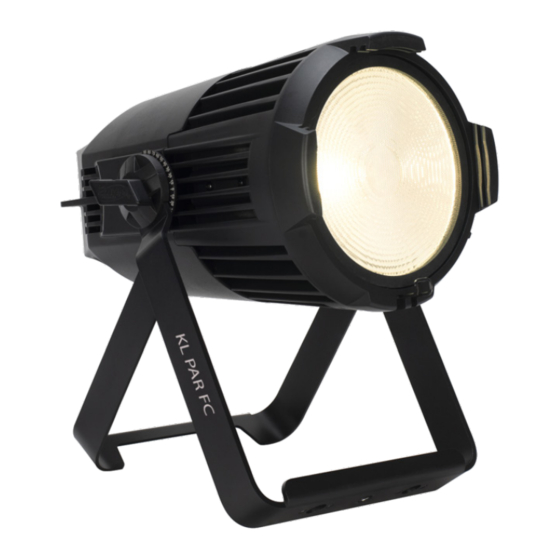
Page 9: Overview
OVERVIEW... -
Page 10: Fixture Installation
FIXTURE INSTALLATION FLAMMABLE MATERIAL WARNING Keep fixture minimum 5.0 feet (1.5m) away from flammable materials and/or pyrotech- nics. ELECTRICAL CONNECTIONS A qualified electrician should be used for all electrical connections and/or installations. MINIMUM DISTANCE TO OBJECTS/SURFACES IS 1 FOOT (0.3 METERS) MINIMUM DISTANCE OF FLAMMABLE MATERIALS FROM THE SURFACE IS 1.6 FEET (0.5 METER) MAXIMUM AMBIENT TEMPERATURE 113°... - Page 11 FIXTURE INSTALLATION CLAMP INSTALLATION This device features a mounting clamp attachment point built into the mounting bracket, as well as two safety cable attachment points located on the rear face of the fixture on either side of the con- trol panel (see the illustration below). When mounting the fixture to a truss or any other suspended or overhead installation, be sure to secure an appropriately rated clamp (not included) to the clamp attachment point and attach a separate SAFETY CABLE of the appropriate safety rating to the safe- ty cable rigging point.
-
Page 12: Accessory Installation
ACCESSORY INSTALLATION LENS INSTALLATION 1. Flip the retaining clip located near the 2. Push the latch towards the location of the re- top of the lens. taining clip. Hold the latch in this position. 3. While holding the latch in place, slide the 4. - Page 13 ACCESSORY INSTALLATION BARNDOOR INSTALLATION 1. Flip the retaining clip located near the 2. Slide the barn door into place in one of the va- top of the lens. cant accessory slots on the front of the fixture. 3. Return the retaining clip to the original position to lock the barndoor in place.
-
Page 14: Control Panel
CONTROL PANEL The fixture includes an easy to navigate system menu. The control panel display is located on the rear panel of the fixture (see image below) and provides access to the main system menu, where all necessary system adjustments are made to the fixture. During normal operation, pressing the MODE button once will access the fixture’s main menu. -
Page 15: System Menu
SYSTEM MENU ELATION KL PAR FC Supports Software Versions: 1.03 Disabled For use when running fixture in DMX mode Dimmer For use when running fixture in dimmer mode Int CCT Grn For use when running fixture in CCT mode with encoder control... - Page 16 SYSTEM MENU ELATION KL PAR FC Supports Software Versions: 1.03 900Hz - 1500Hz, 2500Hz, 4000Hz, 5000Hz, 6000Hz, 10KHz, LED Refresh Rate 15KHz, 20KHz, 25KHz (Default = 1200 Hz) LED Power Limit 100% Auto Fan Mode Silent High PERSONALITY 10s - 5min (Default = 1 min)
-
Page 17: Encoder Function
ENCODER FUNCTION When the device has been set to Encoder mode, the lighting display can be adjusted using the knob located beside the display screen on the back of the device. To enter Encoder mode, select the ENCODER MODE option from the main system menu, as de- scribed in the System Menu section of this manual. -
Page 18: Dmx Channels Functions
DMX CHANNEL FUNCTIONS ELATION KL PAR FC Supports Software Versions: 1.03 Dimmer Dimmer Standard Extended Color Extended Function 11CH 18CH Values 14CH 000 - 255 Dimmer, 0% to 100% 000 - 255 Dimmer Fine Strobe 000 - 031 Shutter closed... - Page 19 DMX CHANNEL FUNCTIONS ELATION KL PAR FC Supports Software Versions: 1.03 Dimmer Dimmer Standard Extended Color Extended Function 11CH 18CH Values 14CH 000 - 023 Open CTO 2400K - 8500K (see Color Tem- 024 - 085 perature Table) 086 - 255 8500K...
- Page 20 DMX CHANNEL FUNCTIONS ELATION KL PAR FC Supports Software Versions: 1.03 Dimmer Dimmer Standard Extended Color Extended Function 11CH 18CH Values 14CH Dimmer Delay Time 0.1s 0.2s 0.3s 0.4s 0.5s 0.6s 0.7s 0.8s 0.9s 1.0s 1.5s 2.0s 3.0s 4.0s 5.0s 6.0s...
- Page 21 DMX CHANNEL FUNCTIONS ELATION KL PAR FC Supports Software Versions: 1.03 Dimmer Dimmer Standard Extended Color Extended Function 11CH 18CH Values 14CH Refresh Rate (Hz) 1000 1010 1020 1030 1040 1050 1060 1070 1080 1090 1100 1110 1120 1130 1140...
- Page 22 DMX CHANNEL FUNCTIONS ELATION KL PAR FC Supports Software Versions: 1.03 Dimmer Dimmer Standard Extended Color Extended Function 11CH 18CH Values 14CH Refresh Rate (Hz) (continued) 1220 1230 1240 1250 1260 1270 1280 1290 1300 1310 1320 1330 1340 1350...
- Page 23 DMX CHANNEL FUNCTIONS ELATION KL PAR FC Supports Software Versions: 1.03 Dimmer Dimmer Standard Extended Color Extended Function 11CH 18CH Values 14CH Refresh Rate (Hz) (continued) 5000 6000 10000 15000 20000 25000 169 - 200 Idle 201 - 210 Dimmer Curve Linear (Default)
-
Page 24: Dimmer Modes & Curves
DIMMER MODES & CURVES... -
Page 25: Color Temperature Chart
COLOR TEMPERATURE CHART DMX VALUE COLOR TEMPERATURE (K) DMX VALUE COLOR TEMPERATURE (K) 2400 5500 2500 5600 2600 5700 2700 5800 2800 5900 2900 6000 3000 6100 3100 6200 3200 6300 3300 6400 3400 6500 3500 6600 3600 6700 3700 6800 3800 6900... -
Page 26: Color Macros Chart
COLOR MACROS CHART... -
Page 27: Dimensional Drawings
DIMENSIONAL DRAWINGS... -
Page 28: Specifications
SPECIFICATIONS SOURCE INCLUDED ITEMS 6500K RGBMA LED Engine 7.5” Gel Frame 50,000 Hour Average LED Life* 4x Lenses (11°, 22°, 30°, 52°) *May vary depending on several factors including but not IP65 Locking Power Cable limited to: OPTIONAL ITEMS Environmental Conditions, Power/Voltage, Usage Patterns (On-Off Cycling), Control and Dimming. -
Page 29: Ordering Information | Error Codes
ORDERING INFORMATION ITEM DESCRIPTION Elation KL Par FC KLP500 7.5” Barndoors KLP959 Glass Ovalizer Lens KLP988 XWFL Lens KLP987 ERROR CODES CODE ERROR TEMP Temperature Error...
Need help?
Do you have a question about the KL PAR FC and is the answer not in the manual?
Questions and answers