
Related Manuals for GEM 629 eSyLite


Summary of Contents for GEM 629 eSyLite
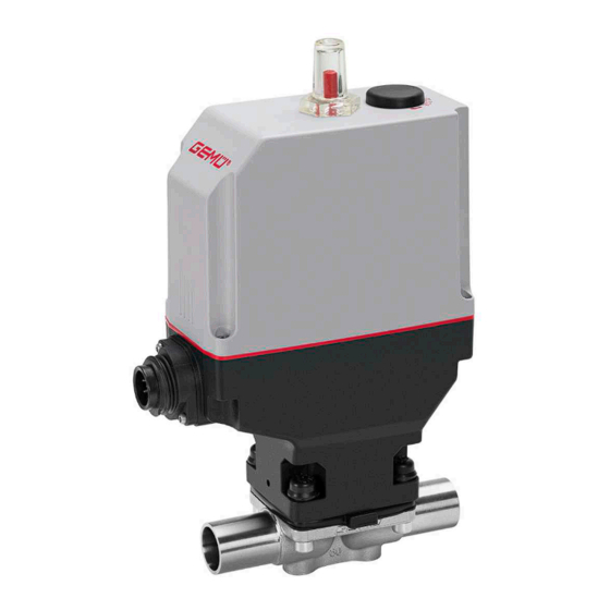
- Page 1 GEMÜ 629 eSyLite Motorized diaphragm valve Operating instructions further information TYPE EL webcode: GW-629 CLASS I AUGUST 2021...
- Page 2 All rights including copyrights or industrial property rights are expressly reserved. Keep the document for future reference. © GEMÜ Gebr. Müller Apparatebau GmbH & Co. KG 02.11.2023 GEMÜ 629 eSyLite 2 / 45 www.gemu-group.com...
-
Page 3: Table Of Contents
Actuator duty cycle and service life ..... 8 Electrical connection ........... 9 Dimensions ............Actuator dimensions ........Actuator dimensions with distance piece ... Actuator dimensions with GEMÜ 1215 posi- tion indicator ..........Actuator dimensions with GEMÜ 1235 posi- tion indicator ..........Body dimensions ........... -
Page 4: General Information ............................................. 4 16 Returns
Hot plant components! Working medium The medium that flows through the GEMÜ product. Diaphragm size Uniform seat size of GEMÜ diaphragm valves for different Damage to the product! nominal sizes. 1.4 Warning notes Wherever possible, warning notes are organised according to... -
Page 5: Safety Information
1.4435 (BN2), forged body, Δ Fe < turer first. 0.5 % 1.4435, investment casting In cases of uncertainty: 1.4539, forged body 15. Consult the nearest GEMÜ sales office. CW614N, CW617N (brass) Electrical connec- tion www.gemu-group.com 5 / 45 GEMÜ 629 eSyLite... -
Page 6: Description
Consecutive number The month of manufacture is encoded in the traceability num- DANGER ber and can be obtained from GEMÜ. The product was manu- factured in Germany. Danger of explosion! The operating pressure stated on the product label applies to ▶... -
Page 7: Order Data
Threaded connection EN-GJS-400-18-LT (GGG 40.3) Threaded socket DIN ISO 228 Investment casting material NPT female thread 1.4408, investment casting Threaded spigot DIN 11851 1.4408, PFA lined Cone spigot and union nut DIN 11851 www.gemu-group.com 7 / 45 GEMÜ 629 eSyLite... -
Page 8: Special Version
Ra max. 0.51 µm (20 µin.) for media wetted surfaces, Emergency power supply module (NO) in accordance with ASME BPE SF5, electropolished internal/external OPEN/CLOSE control with mounted GEMÜ 1235 position indicator Ra max. 0.64 µm (25 µin.) for media wetted surfaces, in accordance with ASME BPE SF6, OPEN/CLOSE control with mounted GEMÜ... -
Page 9: Order Example
9 Surface 1503 Ra ≤ 0.8 µm (30 µin.) for media wetted surfaces, in accordance with DIN 11866 HE3, electropolished internal/external 10 Actuator version Actuator size 3 diaphragm size 40 11 CONEXO Without www.gemu-group.com 9 / 45 GEMÜ 629 eSyLite... -
Page 10: Technical Data
Therefore the Kv values may exceed the tolerance limits of the stand- ard. The Kv value curve (Kv value dependent on valve stroke) can vary depending on the diaphragm material and dur- ation of use. GEMÜ 629 eSyLite 10 / 45 www.gemu-group.com... -
Page 11: Product Compliance
2014/68/EU ective: Food: Regulation (EC) No. 1935/2004* Regulation (EC) No. 10/2011* FDA* USP* Class VI EMC Directive: 2014/30/EU Drinking water: Belgaqua* * depending on version and / or operating parameters RoHS Directive: 2011/65/EU www.gemu-group.com 11 / 45 GEMÜ 629 eSyLite... -
Page 12: Mechanical Data
2.80 0.63 1.45 0.88 1.40 0.88 1.66 3.40 1.62 1.32 0.93 1.90 0.93 1.62 4.50 1.50 2.25 1.56 2.70 1.56 2.70 6.30 2.50 2.20 10.30 2.30 MG = diaphragm size, weight in kg GEMÜ 629 eSyLite 12 / 45 www.gemu-group.com... -
Page 13: Actuator Duty Cycle And Service Life
MG 10, MG 20, MG 25: max. 0.16 A MG 40: 0.32 A MG 50: not available Charging time: approx. 13 min Service life: Guide value at 25 °C ambient temperature, approx. 3 years www.gemu-group.com 13 / 45 GEMÜ 629 eSyLite... -
Page 14: Electrical Connection
Preferred direction if both digital inputs are present for device version 00 (see operating instructions – Product label) Control module ordering Preferred direction option A0, Y0, Z0 OPEN A1, Y1, Z1 CLOSED GEMÜ 629 eSyLite 14 / 45 www.gemu-group.com... - Page 15 Connections / customer Uv 24 V DC eSyLite Power supply Uv GND Digital input 1 24 V DC Digital input 2 24 V DC 7-pin plug Binder, type 693 Switch Consumer Signal direction Power supply www.gemu-group.com 15 / 45 GEMÜ 629 eSyLite...
-
Page 16: Dimensions
63.0 59.5 134.5 115.0 82.0 204.0 75.0 59.5 134.5 115.0 82.0 228.0 91.0 80.0 167.0 147.5 94.5 Dimensions in mm MG = diaphragm size * CT = A + H1 (see body dimensions) GEMÜ 629 eSyLite 16 / 45 www.gemu-group.com... -
Page 17: Actuator Dimensions With Distance Piece
9.2 Actuator dimensions with distance piece 265.0 128.0 80.0 167.0 147.5 94.5 Dimensions in mm MG = diaphragm size * CT = A + H1 (see body dimensions) MG 50 with metal distance piece www.gemu-group.com 17 / 45 GEMÜ 629 eSyLite... -
Page 18: Actuator Dimensions With Gemü 1215 Position Indicator
9 Dimensions 9.3 Actuator dimensions with GEMÜ 1215 position indicator 256.0 72.0 61.0 30.0 40.0 237.0 72.0 61.0 30.0 40.0 249.0 72.0 61.0 30.0 40.0 273.0 72.0 61.0 30.0 40.0 310.0 72.0 61.0 30.0 40.0 Dimensions in mm MG = diaphragm size MG 50 with metal distance piece GEMÜ... -
Page 19: Actuator Dimensions With Gemü 1235 Position Indicator
9 Dimensions 9.4 Actuator dimensions with GEMÜ 1235 position indicator Dia. BZ1 276,0 92,0 45,0 60,0 40,5 257,0 92,0 45,0 60,0 40,5 269,0 92,0 45,0 60,0 40,5 293,0 92,0 45,0 60,0 40,5 330,0 92,0 45,0 60,0 40,5 Dimensions in mm... -
Page 20: Body Dimensions
Code 60: Spigot ISO 1127/DIN EN 10357 series C (2014 edition)/DIN 11866 series B 2) Valve body material Code 40: 1.4435 (F316L), forged body Code 42: 1.4435 (BN2), forged body, Δ Fe < 0.5% Code C3: 1.4435, investment casting Code F4: 1.4539, forged body GEMÜ 629 eSyLite 20 / 45 www.gemu-group.com... - Page 21 Code 17: Spigot EN 10357 series A/DIN 11866 series A formerly DIN 11850 series 2 Code 60: Spigot ISO 1127/DIN EN 10357 series C (2014 edition)/DIN 11866 series B 2) Valve body material Code C3: 1.4435, investment casting www.gemu-group.com 21 / 45 GEMÜ 629 eSyLite...
- Page 22 Code 65: Spigot ANSI/ASME B36.19M schedule 40s 2) Valve body material Code 40: 1.4435 (F316L), forged body Code 42: 1.4435 (BN2), forged body, Δ Fe < 0.5% Code C3: 1.4435, investment casting Code F4: 1.4539, forged body GEMÜ 629 eSyLite 22 / 45 www.gemu-group.com...
- Page 23 Code 37: Spigot SMS 3008 2) Valve body material Code 40: 1.4435 (F316L), forged body Code 42: 1.4435 (BN2), forged body, Δ Fe < 0.5% Code C3: 1.4435, investment casting Code F4: 1.4539, forged body www.gemu-group.com 23 / 45 GEMÜ 629 eSyLite...
- Page 24 = number of flats 1) Connection type Code 1: Threaded socket DIN ISO 228 2) Valve body material Code 12: CW614N, CW617N (brass) Code 37: 1.4408, investment casting Code 90: EN-GJS-400-18-LT (GGG 40.3) GEMÜ 629 eSyLite 24 / 45 www.gemu-group.com...
- Page 25 Dimensions in mm MG = diaphragm size n = number of flats 1) Connection type Code 31: NPT female thread 2) Valve body material Code 37: 1.4408, investment casting Code 90: EN-GJS-400-18-LT (GGG 40.3) www.gemu-group.com 25 / 45 GEMÜ 629 eSyLite...
- Page 26 MG = diaphragm size 1) Connection type Code 6: Threaded spigot DIN 11851 2) Valve body material Code 40: 1.4435 (F316L), forged body Code 42: 1.4435 (BN2), forged body, Δ Fe < 0.5% GEMÜ 629 eSyLite 26 / 45 www.gemu-group.com...
- Page 27 MG = diaphragm size 1) Connection type Code 6K: Cone spigot and union nut DIN 11851 2) Valve body material Code 40: 1.4435 (F316L), forged body Code 42: 1.4435 (BN2), forged body, Δ Fe < 0.5% www.gemu-group.com 27 / 45 GEMÜ 629 eSyLite...
- Page 28 Code 40: 1.4435 (F316L), forged body Code 42: 1.4435 (BN2), forged body, Δ Fe < 0.5% Code 83: EN-GJS-400-18-LT (GGG 40.3), hard rubber lined Code 90: EN-GJS-400-18-LT (GGG 40.3) Code C3: 1.4435, investment casting GEMÜ 629 eSyLite 28 / 45 www.gemu-group.com...
-
Page 29: Flange Jis (Code 34)
Code 34: Flange JIS B2220, 10K, RF, face-to-face dimension FTF EN 558 series 1, ISO 5752, basic series 1, length only for body configura- tion D 2) Valve body material Code 39: 1.4408, PFA lined www.gemu-group.com 29 / 45 GEMÜ 629 eSyLite... - Page 30 Code 40: 1.4435 (F316L), forged body Code 42: 1.4435 (BN2), forged body, Δ Fe < 0.5% Code 83: EN-GJS-400-18-LT (GGG 40.3), hard rubber lined Code 90: EN-GJS-400-18-LT (GGG 40.3) Code C3: 1.4435, investment casting GEMÜ 629 eSyLite 30 / 45 www.gemu-group.com...
- Page 31 Code 8T: Clamp DIN 32676 series C, face-to-face dimension FTF EN 558 series 7, length only for body configuration D 2) Valve body material Code 40: 1.4435 (F316L), forged body Code 42: 1.4435 (BN2), forged body, Δ Fe < 0.5% Code F4: 1.4539, forged body www.gemu-group.com 31 / 45 GEMÜ 629 eSyLite...
- Page 32 Code 8E: Clamp ISO 2852 for pipe ISO 2037, clamp SMS 3017 for pipe SMS 3008, face-to-face dimension FTF EN 558 series 7, length only for body configuration D 2) Valve body material Code 40: 1.4435 (F316L), forged body Code 42: 1.4435 (BN2), forged body, Δ Fe < 0.5% Code F4: 1.4539, forged body GEMÜ 629 eSyLite 32 / 45 www.gemu-group.com...
-
Page 33: Manufacturer's Information
3. Do not exceed the maximum storage temperature (see chapter "Technical data"). CAUTION 4. Do not store solvents, chemicals, acids, fuels or similar fluids in the same room as GEMÜ products and their spare Exceeding the maximum permissible pressure. parts. ▶ Damage to the product Provide precautionary measures against exceeding the ●... -
Page 34: Installation Position
4. Connect the gasket between the body of the product and the pipe connection using clamps. Fig. 4: Threaded spigots 5. Re-attach or reactivate all safety and protective devices. GEMÜ 629 eSyLite 34 / 45 www.gemu-group.com... -
Page 35: Installation With Flanged Connection
8. Use all flange holes. 9. Tighten the bolts diagonally. 2. Operate the manual override 3 with the hexagon socket (WAF3). ð Turn clockwise to close the valve. 10. Re-attach or reactivate all safety and protective devices. www.gemu-group.com 35 / 45 GEMÜ 629 eSyLite... - Page 36 12 Operation ð Turn anticlockwise to open the valve. 3. After actuation, the plug must be reinserted, otherwise the IP protection is no longer guaranteed and the actuator may be damaged. GEMÜ 629 eSyLite 36 / 45 www.gemu-group.com...
- Page 37 Retighten mounting parts flange and valve body Valve body / actuator damaged Replace valve body/actuator Valve body of the GEMÜ product is leak- Valve body of the GEMÜ product is faulty Check valve body of the GEMÜ product or corroded...
-
Page 38: Inspection And Maintenance
5. Depressurize the plant or plant component. 14.3 Removing the diaphragm 6. Actuate GEMÜ products which are always in the same po- 1. Remove actuator A (see chapter "Removing the actuator"). sition four times a year. 2. Unscrew the diaphragm. -
Page 39: Mounting The Compressor
10. Press the diaphragm face tightly onto the backing dia- phragm manually so that it returns to its original shape and fits closely on the backing diaphragm. 11. Align the weir of compressor and diaphragm in parallel. www.gemu-group.com 39 / 45 GEMÜ 629 eSyLite... -
Page 40: Mounting The Actuator
8. Align the weir of compressor and diaphragm in parallel. goods can be processed only when this note is completed. If no return delivery note is included with the product, GEMÜ 14.6 Mounting the actuator cannot process credits or repair work but will dispose of the NOTICE goods at the operator's expense. -
Page 41: Ec Machinery Directive 2006/42/Ec, Annex Ii B
EC Machinery Directive 2006/42/EC, Annex II B Machinery Directive introductory text We, the company GEMÜ Gebr. Müller Apparatebau GmbH & Co. KG Fritz-Müller-Strasse 6–8 74653 Ingelfingen-Criesbach, Germany hereby declare under our sole responsibility that the below-mentioned product complies with the relevant essential health and safety requirements in accordance with Annex I of the above-mentioned Directive. -
Page 42: 18 Eu Declaration Of Conformity In Accordance With 2014/68/Eu (Pressure Equipment Directive)
Information for products with a nominal size ≤ DN 25: The products are developed and produced according to GEMÜ's in-house process instructions and standards of quality which comply with the requirements of ISO 9001 and ISO 14001. According to Article 4, Paragraph 3 of the Pressure Equipment Direct- ive 2014/68/EU, these products must not be identified by a CE-marking. -
Page 43: 2014/30/Eu (Emc Directive)
2014/30/EU (EMC Directive) EMC introductory text We, the company GEMÜ Gebr. Müller Apparatebau GmbH & Co. KG Fritz-Müller-Strasse 6–8 74653 Ingelfingen-Criesbach, Germany hereby declare under our sole responsibility that the below-mentioned product complies with the regulations of the above-men- tioned Directive. -
Page 44: Eu Declaration Of Conformity In Accordance With 2011/65/Eu (Rohs Directive)
In accordance with 2011/65/EU (RoHS Directive) EMC introductory text We, the company GEMÜ Gebr. Müller Apparatebau GmbH & Co. KG Fritz-Müller-Strasse 6–8 74653 Ingelfingen-Criesbach, Germany hereby declare under our sole responsibility that the below-mentioned product complies with the regulations of the above-men- tioned Directive. - Page 45 GEMÜ Gebr. Müller Apparatebau GmbH & Co. KG Fritz-Müller-Straße 6-8, 74653 Ingelfingen-Criesbach, Germany Subject to alteration Phone +49 (0) 7940 1230 · info@gemue.de www.gemu-group.com 11.2023 | 88767818...
Need help?
Do you have a question about the 629 eSyLite and is the answer not in the manual?
Questions and answers