Sign In
Upload
Manuals
Brands
Vaisala Manuals
Measuring Instruments
GMP252
User Manuals: Vaisala GMP252 Carbon Dioxide Probe
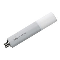
Manuals and User Guides for Vaisala GMP252 Carbon Dioxide Probe. We have
4
Vaisala GMP252 Carbon Dioxide Probe manuals available for free PDF download: User Manual, Quick Manual, Quick Start Manual
Vaisala GMP252 User Manual (132 pages)
Carbon Dioxide Probe
Brand:
Vaisala
| Category:
Measuring Instruments
| Size: 3 MB
Table of Contents
Table of Contents
3
About this Document
11
Version Information
11
Table Document Versions (English)
11
Related Manuals
12
Documentation Conventions
12
Table 2 Related Manuals
12
Trademarks
13
Product Overview
14
Introduction to GMP252
14
Basic Features and Options
15
Connectivity to Vaisala Insight Software
15
Additional Features with Indigo Transmitters
16
Filter Options
17
Figure 2 ASM212011SP Flow-Through Adapter
17
Operating Principle of CO Measurement
18
Figure 3 Probe Cuvette with Mirror and Sensor Chips
18
Environmental Compensation
19
Figure 4 CO 2 Measurement in the Measurement Cuvette
19
Temperature Compensation
20
Pressure Compensation
21
Background Gas Compensation
21
Probe Startup
21
Filtering Factor
21
Analog Output Overrange Behavior
22
Table 3 Analog Output Overrange Clipping and Error Limits
22
Analog Output Overrange Example
23
Figure 5 Example of Analog Output Overrange Behavior
23
Safety
24
ESD Protection
24
Installation
25
GMP252 Probe Dimensions
25
Recommended Installation
25
Figure 6 GMP252 Dimensions
25
Installation Accessories
26
243261SP Mounting Flange
27
Figure 7 Probe with 243261SP Mounting Flange
27
243257SP Mounting Clips
28
ASM213582 Probe Holder
28
Figure 8 Probe in 243257SP Mounting Clips
28
ASM212017SP Spray Shield
29
Figure 9 Probe Holder ASM213582 Dimensions
29
Figure 10 Probe with ASM212017SP Spray Shield
29
DTR250 Radiation Shield
30
DTR250A Pole Mounting Kit
30
Figure 11 GMP252 in DTR250 Radiation Shield
30
GMP252 Probe Handle Accessories
31
Figure 12 GMP252 Installation with DTR250A Pole Mounting Kit
31
Figure 13 Fastening Magnetic Hanger to GMP252 Probe Handle
32
Power Supply
33
Wiring
33
Figure 14 GMP252 Probe Handle Dimensions
33
Table 4 M12 Male Connector
33
Vaisala Industrial Protocol
35
Vaisala Industrial Protocol Overview
35
Serial Interface Settings
35
Physical Interface
35
Connecting with a Computer
35
Table 5 Default Serial Interface Settings
35
Installing Driver for the USB Service Cable
37
Accessing Serial Commands from Modbus or Analog Mode
38
Enabling Modbus Mode from Vaisala Industrial Protocol
39
Changing from Digital Output to Analog Output
39
Serial Commands
40
Table 6 Basic Serial Commands
40
Table 7 Advanced Serial Commands
41
Device Information and Status
42
Table 8 ? Command
42
Table 9 Errs Command
42
Table 10 Help Command
42
Table 11 Snum Command
43
Table 12 System Command
43
Serial Line Output and Communication
44
Table 13 Time Command
44
Table 14 Vers Command
44
Table 15 Addr Command
44
Table 16 Close Command
45
Table 17 Form Command
45
Table 18 Output Parameters for Form Command
46
Table 19 Modifiers for Form Command
46
Table 20 Intv Command
47
Table 21 Open Command
48
Table 22 R Command
48
Table 23 S Command
48
Table 24 Sdelay Command
49
Table 25 Send Command
49
Table 26 Seri Command
50
Table 27 Smode Command
50
Analog Output
51
Table 28 Amode Command
51
Table 29 Aover Command
52
Figure 15 Example of Analog Output Overrange Behavior
55
Table 30 Asel Command
55
Calibration and Adjustment Commands
56
Table 31 Adate Command
56
Table 32 Atext Command
57
Table 33 Cdate Command
57
Table 34 Ctext Command
57
Table 35 Cco2 Command
58
Environmental Compensation Commands
60
Table 36 Env Command
60
Table 37 O2Cmode Command
62
Table 38 Pcmode Command
63
Table 39 Rhcmode Command
63
Table 40 Tcmode Command
64
Other Commands
65
Table 41 Frestore Command
65
Table 42 Pass Command
65
Table 43 Reset Command
65
Modbus
66
Table 44 Default Modbus Serial Communication Settings
66
Vaisala Insight PC Software
67
Connecting to Insight Software
67
Figure 16 Connecting Probe to Insight
67
Using Probe with Indigo200 Series Transmitters
69
Introduction to Indigo200 Transmitters
69
Figure 17 Indigo201 with and Without Display
69
Connecting Probes
70
Figure 18 Connecting Probes and Cables to Indigo200
70
Analog Output Configuration Overview
71
Figure 19 Analog Output Configuration Options Example in Insight
71
Analog Output Configuration Example
72
Modbus Overview
72
Figure 20 Analog Output Type (Current or Voltage) Selection in Insight
72
Table 45 Indigo202 Modbus Registers
73
Default Communication Settings
74
Relay Configuration Overview
74
Figure 21 Insight PC Software Communication Menu View
74
Table 46 Default Modbus Serial Communication Settings
74
Figure 22 Relay Configuration Options (CO2 Probe Example)
75
Configuring Filtering Factor with Insight
76
Figure 23 Relay Icons on Display (Relay a Active, Relay B Not Active)
76
Figure 24 Filtering Factor Setting in Insight
76
Using Probe with Indigo80 Handheld Indicator
78
Indigo80 Handheld Indicator
78
Figure 25 Indigo80 Handheld Indicator
78
Probe Compatibility
79
Indigo80 Keypad
79
Indigo80 Main Menu
79
Figure 26 Indigo80 Keypad
79
Figure 27 Indigo80 Main Menu
79
Connecting Probes to Indigo80
80
Figure 28 Connecting Probes to Indigo80
80
Configuring Probe Features with Indigo80 Handheld Indicator
81
Example of Configuring Filtering Factor with Indigo80 Handheld Indicator
82
Configuring Environment Settings with Indigo80 Handheld Indicator
83
Operating with MI70 Indicator
85
Overview of MI70 Support
85
Probe Warm-Up and MI70 Automatic Power off
85
Basic Display
85
Figure 29 MI70 Basic Display
85
Graphical Display
86
Main Menu
86
Connecting Probe to MI70 Indicator
86
MI70 Indicator Parts
87
Holding and Saving the Display
87
Figure 30 MI70 Indicator Parts
87
Recording Data
88
Changing Environmental Compensation Settings with MI70 Indicator
88
Figure 31 CO 2 Reading with Tcomp and Pcomp on MI70 Screen
88
Figure 32 Probe Compensation Settings on MI70 Screen
89
Calibration and Adjustment
90
Calibration Setup
90
Effect of Environmental Compensations
91
Limits of Adjustment
91
Adjustment Types
91
DRW244827SP Calibration Adapter
93
Figure 33 DRW244827SP Calibration Adapter with Probe Inserted
93
Overview of Calibration with Indigo200 Using Insight
94
Figure 34 Insight Calibration Menu Main View (CO 2 Probe)
94
Environmental Compensation
95
Figure 35 Insight Calibrate Menu Selection
95
Figure 36 Insight Restore Factory Adjustment Selection
95
CO 2 Probe Adjustment Example
96
Figure 37 Insight Environmental Compensation Configuration
96
Performing Manual Adjustment with Indigo80 Handheld Indicator
97
Restoring Factory Adjustment with Indigo80 Handheld Indicator
98
Calibration and Adjustment with MI70 Indicator
99
1-Point Adjustment with an MI70-Compatible Reference Probe
99
1-Point Adjustment with a Reference Gas
101
Maintenance
104
Cleaning
104
Chemical Tolerance
104
Changing the Filter
105
Figure 38 Opening the Filter
105
Troubleshooting
106
Problem Situations
106
Error Messages
106
Analog Output Error State
108
Technical Data
109
GMP252 Specifications
109
Table 47 GMP252 Measurement Performance
109
Table 48 GMP252 Operating Environment
110
Table 49 GMP252 Inputs and Outputs
111
Table 50 GMP252 Mechanical Specifications
111
Spare Parts and Accessories
112
Table 51 GMP252 Compliance
112
Table 52 GMP252 Spare Parts and Accessories
112
GMP252 Probe Dimensions
113
Figure 39 GMP252 Dimensions
113
243261SP Mounting Flange Dimensions
114
Figure 40 243261SP Mounting Flange Dimensions
114
Figure 41 243261SP Mounting Flange Dimensions, Cross Section
114
DRW244827SP Calibration Adapter Dimensions
115
ASM212017SP Spray Shield Dimensions
115
Figure 42 DRW244827SP Calibration Adapter Dimensions
115
Figure 43 ASM212017SP Spray Shield Dimensions
115
Figure 44 GMP252 Spray Shield Cross Section
116
DTR250 Radiation Shield Dimensions
117
Figure 45 DTR250 Radiation Shield Dimensions (MM)
117
DTR250A Pole Mounting Kit Dimensions
118
Figure 46 DTR250A Pole Mounting Kit Dimensions (in MM [Inch])
118
Appendix A: Modbus Reference
119
Default Communication Settings
119
Function Codes
119
Data Encoding
119
32-Bit Floating Point or 32-Bit Integer Format
119
Table 53 Default Modbus Serial Communication Settings
119
Table 54 Modbus Function Codes
119
16-Bit Integer Format
120
Modbus Registers
120
Table 55 Interpretation of 16-Bit Signed Integer Values
120
Measurement Data Registers
121
Configuration Registers
121
Table 56 Modbus Measurement Data Registers (Read-Only)
121
Table 57 Modbus Configuration Data Registers (Writable)
121
Status Registers
123
Table 58 Modbus Status Registers (Read-Only)
123
Table 59 Error Codes in Register 0803
124
Device Identification Objects
125
Exception Responses
125
Table 60 Device Identification Objects
125
Table 61 Modbus Exception Responses
125
Modbus Communication Examples
126
Filtering Factor
128
Advertisement
Vaisala GMP252 User Manual (126 pages)
CARBOCAP Carbon Dioxide Probe
Brand:
Vaisala
| Category:
Measuring Instruments
| Size: 6 MB
Table of Contents
Table of Contents
3
1 About this Document
9
Version Information
9
Related Manuals
9
Table 2 Related Manuals
9
Documentation Conventions
10
Trademarks
10
Patent Notice
11
Table 3 Applicable Patents
11
2 Product Overview
13
Introduction to GMP252
13
Figure GMP252 Probe Parts
13
Basic Features and Options
14
Connectivity to Vaisala Insight Software
14
Additional Features with Indigo Transmitters
15
Filter Options
15
Figure 2 ASM212011SP Flow-Through Adapter
15
Operating Principle of CO Measurement
16
Figure 3 Probe Cuvette with Mirror and Sensor Chips
16
Environmental Compensation
17
Figure 4 CO 2 Measurement in the Measurement Cuvette
17
Temperature Compensation
18
Background Gas Compensation
19
Pressure Compensation
19
Probe Startup
19
Filtering Factor
19
Analog Output Overrange Behavior
20
Analog Output Overrange Example
20
Table 4 Analog Output Overrange Clipping and Error Limits
20
Safety
21
Figure 5 Example of Analog Output Overrange Behavior
21
ESD Protection
22
Regulatory Compliances
22
3 Installation
23
GMP252 Probe Dimensions
23
Recommended Installation
23
Installation Accessories
23
Figure 6 GMP252 Dimensions
23
243261SP Mounting Flange
24
Figure 7 Probe with 243261SP Mounting Flange
24
243257SP Mounting Clips
25
ASM212017SP Spray Shield
25
Figure 8 Probe in 243257SP Mounting Clips
25
Figure 9 Probe with ASM212017SP Spray Shield
25
DTR250 Radiation Shield
26
DTR250A Pole Mounting Kit
26
Figure 10 GMP252 in DTR250 Radiation Shield
26
Figure 11 GMP252 Installation with DTR250A Pole Mounting Kit
26
Power Supply
27
Wiring
27
Table 5 M12 Male Connector
27
4 Vaisala Industrial Protocol
29
Vaisala Industrial Protocol Overview
29
Serial Interface Settings
29
Physical Interface
29
Connecting with a Computer
29
Table 6 Default Serial Interface Settings
29
Installing the Driver for the USB Service Cable
31
Accessing Serial Commands from Modbus or Analog Mode
32
Enabling Modbus Mode from Vaisala Industrial Protocol
32
Changing from Digital Output to Analog Output
33
Serial Commands
33
Table 7 Basic Serial Commands
34
Device Information and Status
35
Table 8 Advanced Serial Commands
35
Table 9 ? Command
35
Table 10 Errs Command
36
Table 11 Help Command
36
Table 12 Snum Command
37
Table 13 System Command
37
Serial Line Output and Communication
38
Table 14 Time Command
38
Table 15 Vers Command
38
Table 16 Addr Command
38
Table 17 Close Command
39
Table 18 Form Command
39
Table 19 Output Parameters for Form Command
41
Table 20 Modifiers for Form Command
41
Table 21 Intv Command
42
Table 22 Open Command
42
Table 23 R Command
43
Table 24 S Command
43
Table 25 Sdelay Command
44
Table 26 Send Command
44
Table 27 Seri Command
44
Table 28 Smode Command
45
Analog Output
46
Table 29 Amode Command
46
Table 30 Aover Command
47
Figure 12 Example of Analog Output Overrange Behavior
50
Table 31 Asel Command
50
Calibration and Adjustment
51
Table 32 Adate Command
51
Table 33 Atext Command
51
Table 34 Cdate Command
52
Table 35 Ctext Command
52
Table 36 CCO2 Command
52
Environmental Compensation Commands
54
Table 37 Env Command
55
Table 38 O2Cmode Command
57
Table 39 Pcmode Command
58
Table 40 Rhcmode Command
58
Table 41 Tcmode Command
59
Other Commands
60
Table 42 Frestore Command
60
Table 43 Pass Command
60
Table 44 Reset Command
60
5 Modbus
61
Table 45 Default Modbus Serial Communication Settings
61
6 Vaisala Insight Software
63
Connecting to Insight Software
63
Figure 13 Connecting Probe to Insight
63
7 Using GMP252 with Indigo Transmitters
65
Indigo Overview
65
Figure 14 GMP252 Attached to Indigo Transmitter
65
Figure 15 Desktop and Mobile Example Views
66
Wireless Configuration Interface Overview
66
Taking a Probe in Use with Indigo
67
Checking Indigo Support in Probe
68
Figure 16 Serial Number on Probe Body (GMP251 Example)
68
Attaching Probes and Cables
69
Figure 17 Attaching Probes and Cables to Indigo
69
Connecting to Wireless Configuration Interface
70
Figure 18 Enabling and Accessing Indigo's Wireless Configuration Interface
70
Logging in to Wireless Configuration Interface
71
Figure 19 Indigo Login View
71
Wireless Interface Menus
72
Figure 20 Wireless Configuration Interface, Desktop Browser View
72
Configuring Analog Outputs with Indigo 201
73
Figure 21 Indigo 201 Analog Output Configuration Options
73
Figure 22 Clearing Analog Output Settings
74
Indigo 201 Analog Output Mode Selection
74
Receiving Analog Output Settings from Probe
74
Using Modbus with Indigo 202
75
Figure 23 Selecting Indigo 201 Analog Output Mode
75
Table 46 Indigo 202 Modbus Registers
75
Modbus Serial Communication Settings
76
Configuring Relays with Indigo
77
Figure 24 Relay Configuration Options
77
Changing Environmental Compensation Settings with Indigo
78
Configuring Filtering Factor with Indigo
79
Calibrating GMP252 with Indigo
80
Indigo Calibration Overview
80
Figure 25 Calibration Menu Main View
80
Figure 26 Start Calibration Button
81
Restoring Factory Adjustment
82
Calibration PIN Code
82
1-Point Adjustment with Indigo
82
2-Point Adjustment with Indigo
84
8 Operating with MI70 Indicator
87
Overview of MI70 Support
87
Probe Warm-Up and MI70 Automatic Power off
87
Basic Display
87
Figure 27 MI70 Basic Display
87
Graphical Display
88
Main Menu
88
Connecting Probe to MI70 Indicator
88
MI70 Indicator Parts
89
Holding and Saving the Display
89
Figure 28 MI70 Indicator Parts
89
Recording Data
90
Changing Environmental Compensation Settings with MI70 Indicator
90
Calibration and Adjustment with MI70 Indicator
91
Figure 29 CO 2 Reading with Tcomp and Pcomp on MI70 Screen
91
Figure 30 Probe Compensation Settings on MI70 Screen
91
1-Point Adjustment with an MI70-Compatible Reference Probe
92
1-Point Adjustment with a Reference Gas
93
9 Maintenance
95
Cleaning
95
Chemical Tolerance
95
Changing the Filter
96
Calibration and Adjustment
96
Figure 31 Opening the Filter
96
Calibration Setup
97
Effect of Environmental Compensations
97
Adjustment Types
98
Limits of Adjustment
98
DRW244827SP Calibration Adapter
99
Figure 32 DRW244827SP Calibration Adapter with Probe Inserted
99
10 Troubleshooting
101
Problem Situations
101
Error Messages
101
Analog Output Error State
102
Indigo Wireless Connection Troubleshooting
103
11 Technical Data
105
GMP252 Specifications
105
Table 47 Measurement Performance
105
Table 48 Operating Environment
106
Table 49 Mechanical Specifications
106
Table 50 Inputs and Outputs
107
Spare Parts and Accessories
108
GMP252 Probe Dimensions
109
243261SP Mounting Flange Dimensions
109
Figure 33 GMP252 Dimensions
109
Figure 34 243261SP Mounting Flange Dimensions
109
DRW244827SP Calibration Adapter Dimensions
110
Figure 35 243261SP Mounting Flange Dimensions, Cross Section
110
Figure 36 DRW244827SP Calibration Adapter Dimensions
110
ASM212017SP Spray Shield Dimensions
111
Figure 37 ASM212017SP Spray Shield Dimensions
111
Figure 38 GMP252 Spray Shield Cross Section
111
DTR250 Radiation Shield Dimensions
112
Figure 39 DTR250 Radiation Shield Dimensions (MM)
112
DTR250A Pole Mounting Kit Dimensions
113
Figure 40 DTR250A Pole Mounting Kit Dimensions (in MM [Inch])
113
Appendix A: Modbus Reference
115
Function Codes
115
Modbus Registers
115
Measurement Data
115
Table 51 Supported Function Codes
115
Table 52 Modbus Measurement Data Registers (Read-Only)
115
Configuration Registers
116
Table 53 Modbus Configuration Data Registers (Writable)
116
A.2.2 Configuration Registers
116
Status Registers
118
Table 54 Modbus Status Registers (Read-Only)
118
A.2.3 Status Registers
118
Device Identification Objects
119
Table 55 Device Identification Objects
119
Modbus Communication Examples
120
Filtering Factor
122
A.4 Filtering Factor
122
Warranty
123
Technical Support
123
Recycling
123
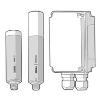
Vaisala GMP252 Quick Manual (14 pages)
Relay Box for GMP250 Carbon Dioxide Probes
Brand:
Vaisala
| Category:
Other
| Size: 0 MB
Advertisement
Vaisala GMP252 Quick Start Manual (2 pages)
CO2 Probe
Brand:
Vaisala
| Category:
Test Equipment
| Size: 0 MB
Advertisement
Related Products
Vaisala CARBOCAP GMP231
Vaisala CARBOCAP GMP343
Vaisala CARBOCAP GMP80P
Vaisala CARBOCAP GM70
Vaisala GC25
Vaisala GMP251
Vaisala CARBOCAP GMW80 Series
Vaisala CARBOCAP GMW84
Vaisala GMW94
Vaisala GMW93
Vaisala Categories
Transmitter
Measuring Instruments
Accessories
Weather Station
Test Equipment
More Vaisala Manuals
Login
Sign In
OR
Sign in with Facebook
Sign in with Google
Upload manual
Upload from disk
Upload from URL